PLANET NMS-AIoT Universal Network Management AIoT Application Server
Product Information
The Universal Network Management AIoT Application Server NMS-AIoT is a licensed product of PLANET Technology Corp. It is designed to provide advanced network management capabilities in AIoT environments.
Specifications:
- Product Name: Universal Network Management AIoT Application Server NMS-AIoT
- Manufacturer: PLANET Technology Corp.
- Model: NMS-AIoT
- Copyright: 2024 PLANET Technology Corp.
- Compliance: FCC Class A, CE Class A, WEEE
- Revision: 1.0 (August 2024)
Product Usage Instructions
Hardware Introduction
Physical Descriptions
Refer to the hardware installation guide for detailed physical descriptions of the NMS-AIoT server.
Hardware Installation
Follow these steps for hardware installation:
- Choose a suitable location for the server with proper ventilation.
- Connect power and network cables to the server.
- Power on the server and follow the on-screen instructions for initial setup.
FAQ:
- Q: What should I do if the server does not power on?
A: Check the power connections and ensure that the power source is functioning correctly. If the issue persists, contact customer support for assistance. - Q: How can I access the network management interface of the NMS-AIoT server?
A: Use a web browser to enter the server’s IP address in the address bar. Log in with the provided credentials to access the management interface.
Copyright
Copyright (C) 2024 PLANET Technology Corp. All rights reserved.
The products and programs described in this User’s Manual are licensed products of PLANET Technology, This User’s Manual contains proprietary information protected by copyright, and this User’s Manual and all accompanying hardware, software, and documentation are copyrighted.
No part of this User’s Manual may be copied, photocopied, reproduced, translated, or reduced to any electronic medium or machine-readable form by any means, electronic or mechanical including photocopying, recording, or information storage and retrieval systems, for any purpose other than the purchaser’s personal use, and without the prior express written permission of PLANET Technology.
Disclaimer
PLANET Technology does not warrant that the hardware will work properly in all environments and applications, and makes no warranty and representation, either implied or expressed, with respect to the quality, performance, merchantability, or fitness for a particular purpose.
PLANET has made every effort to ensure that this User’s Manual is accurate; PLANET disclaims liability for any inaccuracies or omissions that may have occurred. Information in this User’s Manual is subject to change without notice and does not represent a commitment on the part of PLANET. PLANET assumes no responsibility for any inaccuracies that may be contained in this User’s Manual. PLANET makes no commitment to update or keep current the information in this User’s Manual, and reserves the right to make improvements and/or changes to this User’s Manual at any time without notice.
If you find information in this manual that is incorrect, misleading, or incomplete, we would appreciate your comments and suggestions.
FCC Compliance Statement
This Equipment has been tested and found to comply with the limits for a Class A digital device, pursuant to Part 15 of the FCC rules. These limits are designed to provide reasonable protection against harmful interference in a residential installation. This equipment can radiate radio frequency energy and, if not installed and used in accordance with the instructions, may cause harmful interference to radio communications.
However, there is no guarantee that interference will not occur in a particular installation. If this equipment does cause harmful interference to radio or television reception, which can be determined by turning the equipment off and on, the user is encouraged to try to correct the interference by one or more of the following measures:
- Reorient or relocate the receiving antenna.
- Increase the separation between the equipment and receiver.
- Connect the equipment into an outlet on a circuit different from that to which the receiver is connected.
- Consult the dealer or an experienced radio/TV technician for help.
CE mark Warning
This device is compliant with Class A of CISPR 32. In a residential environment this equipment may cause radio interference.
WEEE
To avoid the potential effects on the environment and human health as a result of the presence of hazardous substances in electrical and electronic equipment, end users of electrical and electronic equipment should understand the meaning of the crossed-out wheeled bin symbol. Do not dispose of WEEE as unsorted municipal waste and have to collect such WEEE separately.
Trademarks
The PLANET logo is a trademark of PLANET Technology. This documentation may refer to numerous hardware and software products by their trade names. In most, if not all cases, these designations are claimed as trademarks or registered trademarks by their respective companies.
Revision
User’s Manual of Universal Network Management AIoT Application Server
Model: NMS-AIoT
Rev.: 1.0 (August 2024)
Part No. EM-NMS-AIoT_v1.0
Product Introduction
Thank you for purchasing PLANET Universal Network Management AIoT Application Server. PLANET NMS-AIoT is described below:
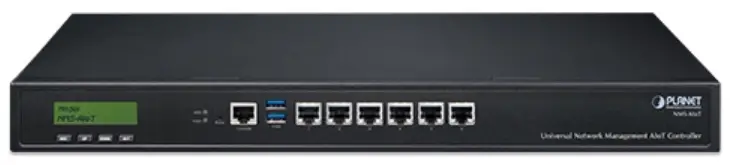
- NMS-AIoT: Universal Network Management AIoT Application Server with LCD
Package Contents
Open the box of the NMS-AIoT and carefully unpack it. The box should contain the following items:
If any of the above items are missing, please contact your dealer immediately.
Overview
Universal Network Management AIoT Application Server with LCD
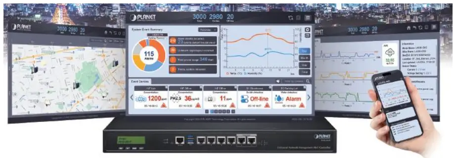
PLANET’s NMS-AIoT (Universal Network Management AIoT) Application Server can directly monitor over 3,000 sensing devices. In the era of edge computing and AIoT (Artificial Intelligence of Things) applications, enterprises require a high-performance, secure, and flexible management platform to integrate various wired and wireless IoT devices and massive environmental data. The NMS-AIoT Application Server offers a comprehensive solution by integrating energy management, wide-area transmission, and AI edge computing, providing an efficient and secure AI private cloud network for enterprises.
PLANET NMS solution features intuitive dashboard, and map viewing to make network management efficient and effective.
The exclusive product features for PLANET NMS solution include:
- ESG energy management reporting with real-time sensor data analysis and carbon footprint reduction
- Supports integration with versatile IoT devices
- Cybersecurity with IEC 62443 certified
- Supports private and PLANET cloud platforms
Unified Platform Integration
The NMS-AIoT platform integrates multiple communication protocols, including LoRa, Wi-Fi HaLow, Modbus, and PDU. This integration allows the management of over 3,000 sensing devices, supporting both wired and wireless connections. It ensures seamless communication and efficient management of various IoT devices across an enterprise’s infrastructure.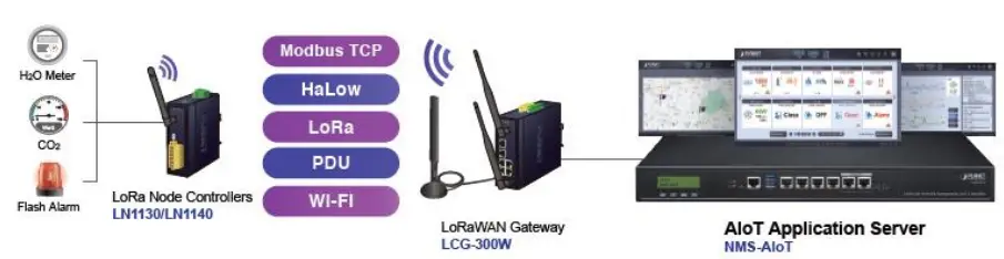
ESG Energy Management Reporting
One of the standout features of the NMS-AIoT is its ability to support ESG (Environmental, Social, and Governance) energy management reporting. The platform provides real-time sensor data analysis and aids in reducing the carbon footprint by optimizing energy usage. This feature is critical for enterprises aiming to achieve sustainability and energy efficiency goals.
Cybersecurity Compliance
Security is a paramount concern in IoT deployments. The NMS-AIoT platform is certified with IEC 62443, ensuring robust cybersecurity measures. It includes SSL VPN and hybrid VPN support, enhancing secure communications and protecting sensitive data from potential cyberthreats.
AI and Edge Computing Integration
The platform leverages AI edge computing capabilities to process data locally at the edge of the network. This reduces latency and enhances the efficiency of data processing. Real-time monitoring and predictive maintenance are enabled, thus optimizing operations and reducing downtime.
Flexible Deployment Options
The NMS-AIoT supports both private and PLANET cloud platforms, offering flexible deployment options for enterprises. This flexibility ensures that the solution can be tailored to specific organizational needs, be it an on-premise or cloud-based platform.
Centralized Intelligent Management Interface
The NMS-AIoT features a Centralized Intelligent Management Interface designed to be intuitive and user-friendly. This interface provides a comprehensive dashboard that offers real-time monitoring and management of all connected IoT devices. With clear visualizations and easy-to-navigate menus, users can quickly access vital information, analyze data, and make informed decisions. The user-centric design ensures that even those with minimal technical expertise can efficiently operate the system, maximizing productivity and minimizing downtime.
Features
- Key Features
- A unified platform integrating LoRa, Wi-Fi, HaLow, Modbus and more
- ESG energy management reporting with real-time sensor data analysis and carbon footprint reduction
- Supports integration with versatile IoT devices
- Intuitive smart dashboard
- Real-time environmental monitoring and analysis
- Precise device location mapping
- 24/7 real-time event notifications
- Early error detection and anomaly resolution
- Embedded hardware controller for easy setup
- Easy installation for non-technical personnel
- Support for future software upgrades
- Support for private and PLANET cloud platforms
- Hardware
- 6x 10/100/1000BASE-T RJ45 LAN ports
- 2x USB 3.0 ports
- 1x serial console port
- 1x reset button
Product Specifications
| NMS-AIoT | |
| Universal Network Management AIoT Application Server with LCD & 6 10/100/1000T LAN Ports | |
| Physical Specifications | |
| I/O Interface | 6 10/100/1000BASE-T Gigabit Ethernet RJ45 ports (LAN 5 and LAN 6 are designed for bypass functionality.) |
| 2 USB 3.0 ports (They cannot be used at the same time.) | |
| 1 factory default button (GPIO) | |
| 1 RJ45 console port | |
| 2 DB-9 COM,COM2 (reserved) | |
| Storage | 2.5″ 64G SATA HDD |
| LED | 2 LED (Power / HDD) |
| LCM Size (Active Area) | 49.45 (W) x 9.58 mm (H) |
| LCM Button | 4 touch buttons for enter, exit, up and down |
| Dimensions (W x D x H) | 438 (W) x 180 (D) x 44 mm (H)
17.24” (W) x 7.09” (D) x 1.73” (H) |
| Weight | 3 kg (6.62 lbs) |
| Form Factor | 1U 19-inch rack-mount |
| Enclosure | Metal |
| Power Requirements | 3-pin AC power input socket
AC 100~240V , 65W |
| Environment & Certification | |
| Temperature | Operating: 0 ~ 50 degrees C
Storage: -20 ~ 70 degrees C |
| Humidity | 5 ~ 90% relative humidity (non-condensing) |
| MTBF (Hours) | 100,000 |
| Network Management | |
| Dashboard | Providing the at-a-glance view of center system, events summary, monitored record of each sensor and real-time alarm status |
| Device List | Manages all sensors and devices in the NMS-AIoT |
| Detail Information | Displays monitoring and history records, the latest 10 events, and current sensor information |
| User Management | Privilege level configuration |
| Event Reports | The alarm event of each sensor can be reported based on customized rules or system updates/changes. |
| Alarm System | Email alerts for the administrator via the SMTP server |
| Automatic Rules | Create one or more customized automatic rules for each sensor |
| Maximum Scalability | 3,000 nodes |
| Standards Conformance | |
| Regulatory Compliance | CE, FCC |
| Standards Compliance | IEEE 802.3 10BASE-T
IEEE 802.3u 100BASE-TX IEEE 802.3ab Gigabit 1000BASE-T |
Hardware Introduction
- Physical Descriptions

- Mechanical Drawing
NMS-AIoT

- Hardware Interface Definition
Interface Description AC IN 100~240V~, 0.59A max. LCM Easy system operation by pressing the button USB Port Connect the USB HDD to enable USB backup/restoration function LAN Ports (1-6) 10/100/1000BASE-T RJ45 auto-MDI/MDI-X ports PWR LED Indicates that the device is powered on (Green ) HDD LED Indicates that the HDD is working (Green )
Hardware Installation
Refer to the illustration and follow the simple steps below to quickly install your NMS-AIoT.
Set up the NMS-AIOT Controller with Ethernet connection for the first-time configuration by following the steps below.
Launch the Web browser (Google Chrome is recommended.) and enter the default IP address “https://192.168.1.100:8888”. Then, enter the default username and password shown above to log on to the system.
The secure login with SSL (HTTPS) prefix is required.
After logging on, connect the NMS-AIoT Controller to the network to centrally control PLANET managed devices.
Preparation
Before getting into the device’s web UI, user has to check the network setting and configure PC’s IP address.
Requirements
User is able to confirm the following items before configuration:
- Please confirm the network is working properly; it is strongly suggested to test your network connection by connecting your computer directly to ISP.
- Suggested operating systems: Windows 7/8/10/11, macOS 10.12 or later, Linux Kernel 2.6.18 or later, and other modern operating systems are compatible with TCP/IP protocols.
- Recommended web browsers: Google Chrome, Microsoft Edge or Mozilla Firefox.
Setting TCP/IP on your PC
The default IP address of the NMS-AIoT is 192.168.1.100. To successfully connect to NMS-AIoT, users need to configure their computer with a static IP address or ensure that a DHCP server is available on their network. Below are the detailed steps.
Method 1: Setting a Static IP Address
- Open Network and Sharing Center
On Windows, right-click the network icon in the taskbar and select “Open Network and Sharing Center.”
On macOS, open “System Preferences” and click on “Network.” - Select the Active Network Connection
On Windows, click on the name of the current network connection (e.g., Ethernet or Wi-Fi). On macOS, select the active network interface from the list on the left (e.g., Wi-Fi or Ethernet). 3. Configure IP Address
On Windows, click “Properties,” then select “Internet Protocol Version 4 (TCP/IPv4)” and click “Properties.”
On macOS, click “Advanced,” then select the “TCP/IP” tab. - Set a Static IP Address
Set the “IP Address” to: 192.168.1.x, where x is any number between 2 and 254 that is not the same as NMS-AIoT’s IP address (192.168.1.100).
Set the Subnet Mask to: 255.255.255.0
Set the Default Gateway to: 192.168.1.1 (If the known gateway address is different, set it accordingly.)
The DNS server addresses can be left blank or set to a public DNS server (e.g., 8.8.8.8). - Save Settings and Close the Window
Click “OK” to save the settings and close all windows. - Test the Connection
Open a web browser and enter https://192.168.1.100 in the address bar to verify that you can connect to the management interface of Device A.
Method 2: Using a DHCP Server
- Ensure a DHCP Server is Available
Make sure that a DHCP server or use PLANET Gateway is running in the current network environment. Typically, home routers have built-in DHCP functionality. - Set the Computer to Obtain an IP Address Automatically
On Windows, follow the steps above to access the “Internet Protocol Version 4 (TCP/IPv4)” settings.
Select “Obtain an IP address automatically” and “Obtain DNS server address automatically”. On macOS, go to the “TCP/IP” settings and set “Configure IPv4” to “Using DHCP”. - Save Settings and Close the Window
Click “OK” or “Apply” to save the settings and close all windows. - Test the Connection
Similarly, enter https://192.168.1.100 in a web browser to verify that you can connect to NMS-AIoT.
Web-based Management
This chapter provides setup details of the device’s Web-based Interface.
Introduction
The device can be configured with your Web browser. Before configuring, please make sure your PC is under the same IP segment with the device.
Logging in to the NMS-AIoT
Refer to the steps below to configure the NMS-AIoT:
- Step 1. Connect the IT administrator’s PC and NMS-AIoT’s LAN port (port 1) to the same hub / switch, and then launch a browser to link the management interface address which is set to https://192.168.1.100 by default.
- Step 2. The browser prompts you for the login credentials. (Both are “admin” by default.)
- Default IP address: 192.168.1.100
- Default user name: admin
- Default password: admin
Administrators are strongly suggested to change the default admin and password to ensure system security.
Dashboard Page
Upon successful login, the main web page will load, displaying the web dashboard with summary information, a sensor history chart, and real-time event alarms.
- Summary Information
The Event Summary displays the daily count of event records, allowing review of data from the past seven days, as shown in Figure 4-3-2.
- Sensor History Chart
The sensor history chart displays alias-based sensor data over daily, weekly, and monthly intervals. Users can also switch to viewing sensors located in different locations, as shown in Figure 4-3-3
- Real-time Event Alarm
The Real-time Event Alarm chart provides an up-to-the-minute display of event alerts as they occur. This chart helps users monitor and respond to critical events in real time, ensuring prompt action and increased situational awareness, as shown in Figure 4-3-4
- Menu and Shortcut
- Shortcut
In the top right corner of the screen, you’ll find several shortcut buttons for quick access to preset screens, along with a menu that consolidates various functions.

- Menu

Object Description Device Management The Device Management feature allows you to manage, monitor, and configure all devices linked to NMS-AIoT. It includes both graphical and text-based views, as well as all automated management options. Map The Map feature allows you to assign a location to each device and place them on various customized maps. System The System feature provides settings pages for configuring NMS-AIoT devices, as well as management pages for NMS-AIoT accounts and groups. Network Services The Network Services feature offers configuration pages for various network services. Maintenance The Maintenance feature includes configuration pages for NMS-AIoT devices, as well as management of system updates, upgrades, data backups, system logs, and event logs. Exit The Exit feature provides options for logging out, rebooting, and shutting down the system.
- Shortcut
Device Management
- Overview page
The graphical interface provides a fast and intuitive way to visualize device status, monitored values, and supervisory conditions. This allows users to easily interpret data, assess system performance, and quickly identify any issues that require attention, all through a visually engaging and informative display.
- Filter Feature
You can quickly display a selected list of sensors by using the location menu, filtering by sensor category, or applying text-based filters. This allows for efficient navigation and easy access to the specific sensors you need.
Clicking on an image allows you to access the device or sensor’s monitoring data, view historical records, check event logs, and review the current configuration settings for the device or sensor.
The following diagram uses the Example LS200-CM3 sensor as a reference.

- Filter Feature
- LS200-CM3: The LoRaWAN 3-phase Current Meter, designed for robust industrial power monitoring, excels with a maximum current measurement of 75A.
The left side of the screen displays sensor device record charts, which can be viewed and marked by day, week, or month in the historical records. Threshold indicators and on-click value displays provide clearer insights into alert monitoring status and associated values.
Displays and statistics for annual, quarterly, and daily data, as well as budget charts for the entire month.
The top right corner displays the current status and information of the selected sensor.
The bottom right corner displays the 10 most recent event records for the selected sensor.
On the sensor information page, there are shortcut keys for editing device settings, configuring automation rules, and resetting the current session.
- Device Edit

- Edit Rule

Device List
The text-based tabular list offers a comprehensive and easily navigable overview of the status of all devices and sensors, allowing you to quickly assess their condition at a glance. The table is designed for efficiency, with multiple shortcut keys that provide instant access to the relevant settings and configurations of any selected device, streamlining your management and ensuring that adjustments can be made swiftly and accurately as shown in Figure 4-4-12.


- Add Device
To add a LoRaWAN Gateway
Object Description Category To select the bindable device category. Device Type To select the bindable device type. Location To assign a location for the new device (default is ‘Default Location’). Module Number To select the bindable module number. Frequency Plan To select a frequency plan for the LoRaWAN gateway. Gateway EUI To enter the DevEUI of LoRaWAN gateway. * Required field
Gateway Name To enter a clear and meaningful gateway name for this LoRaWAN gateway. Gateway ID The ID will be automatically generated by the Gateway EUI.
Add New LoRaWAN Sensor
| Object | Description |
| Category | To select the bindable device category. |
| Device Type | To select the bindable device type. |
| Location | To assign a location for the new device (default is ‘Default Location’). |
| Group | To assign a group for the new device. |
| Module Number | To select the bindable module number. |
| Frequency Plan | To select a frequency plan for the LoRaWAN sensor. |
| Activation Mode | Activation by Personalization (ABP) Over-The-Air-Activation (OTAA) |
| Additional LoRaWAN Class Capabilities | Three device types: Class A, Class B, and Class C |
| DevEUI | The DevEUI uniquely identifies the end device.
* Required field |
| NwkSKey | The Network Session Key (NwkSKey) is used for interaction between the Node and the Network Server.
* Required field |
| Device Address | The end device within the current network.
* Required field |
| AppSKey | The Application Session Key (AppSKey) is used for encryption and decryption of the payload.
* Required field |
| JoinEUI (AppEUI) | The AppEUI uniquely identifies the entity able to process the Join-req frame.
* Required field |
| AppKey | The Application Key (AppKey) is the encryption key used for messages during each over-the-air activation.
* Required field |
| End Device ID | The ID will be automatically generated by the DevEUI. |
Note: The values for DevEUI, NwkSKey, Device Address, AppSKey, AppEUI, or AppKey can be found on the label of the sensor or its packaging, or you can contact the provider.
- Automation Rule
Automation rules help streamline operations, improve efficiency, and ensure that important actions are taken promptly based on real-time data or system events.

Map
This page allows you to mark sensor devices on the uploaded floor plan, enabling quick identification of device status through the map. By visualizing the placement of each device on the floor plan, you can easily monitor and manage your sensor network. The map feature provides a comprehensive view of your setup, making it easier to detect issues, track performance, and optimize the placement of your devices for better coverage and efficiency as shown in Figure 4-4-16.
This page displays Map settings page as shown in Figure 4-4-17.
This page displays Location settings page as shown in Figure 4-4-18.
System
- Date and Time
Time settings and NTP functionality allow you to configure the system clock and synchronize it with a Network Time Protocol (NTP) server. Accurate time synchronization is essential for ensuring that all system logs, event timestamps, and scheduled tasks are consistent and reliable. By using NTP, you can automatically keep the system time accurate, reducing the risk of time-related errors and improving the overall system performance.
This page displays Date and Time settings page as shown in Figure 4-4-19.
- IP Settings
Device IP configuration allows you to set the IP address for the device, ensuring it can communicate effectively within the network. Proper IP address configuration is essential for network connectivity, enabling the device to interact with other devices, access servers, and perform its designated functions. You can configure the device with a static IP address for consistent network performance, or use DHCP to automatically assign an IP address, depending on your network requirements.
This page displays IP settings page as shown in Figure 4-4-20.
- Account Settings
Login account settings allow you to change the account password, with requirements that the password meets high-security standards. This includes criteria such as a minimum length, the use of uppercase and lowercase letters, numerals, and special characters to ensure strong protection against unauthorized access. Regularly updating passwords and adhering to these strong password policies help safeguard your account and maintain system security.
This page displays account setting page as shown in Figure 4-4-21.
- User Management
The User Account Management and Group Settings functions can only be edited and managed by users with the highest level of permissions (admin). This ensures that critical account and group configurations are securely controlled, minimizing the risk of unauthorized changes and maintaining the integrity of the system.
This page displays user settings page as shown in Figure 4-4-22.
This page displays group setting page as shown in Figure 4-4-23.
Network Services
Mail configuration supports email services such as SMTP and Microsoft Exchange Web Server, allowing events to be sent to specified email addresses. This feature ensures that you receive timely notifications about critical events directly in your inbox, enabling swift responses to system alerts. By configuring multiple recipients, you can ensure that the right team members are informed immediately, enhancing the overall reliability and responsiveness of your monitoring system. The Mail Configuration is shown in Figure 4-4-24.
| Object | Description |
| SMTP Email Alarm | Disable or enable the mail function.
The default configuration is disabled. |
| Server Type | Supports SMTP and Microsoft Exchange Web Server mail service. |
| Hostname or IP Address | To enter the mail server hostname or IP address. |
| Port | The mail server port. |
| Username | Username for mail service. |
| Password | Password for mail service. |
| Prefix | Add a custom string to the subject line of outgoing emails. |
Maintenance
- Backup and Restore
The Backup and Restore feature allows you to save and recover device configurations, including network settings, mail configurations, account and group settings, and more. This functionality is crucial for ensuring that your system can be quickly restored to a known good state in the event of a system failure, configuration error, or other issues. Regular backups provide peace of mind, knowing that all critical settings are securely stored and can be easily retrieved to maintain system continuity and integrity.
This page displays Backup and Restore function as shown in Figure 4-4-25.
- Event and Log
Monitoring events and logs allows administrators to review system activity, diagnose issues, and ensure the proper functioning of the system by maintaining a comprehensive history of operations.
‘Events’ typically represent significant actions or changes, such as alarms, notifications, or system status updates, while ‘Logs’ provide a detailed record of these events, including timestamps and other relevant data.
This page displays Events List as shown in Figure 4-4-26.
- Factory Default
This page displays Factory Default setting as shown in Figure 4-4-27.
- System Information
System Information provides details about the device’s current status, including CPU usage, hard drive capacity, memory utilization, and the display of the firmware (FW) version. This information is crucial for monitoring the overall health and performance of the system, helping administrators to identify potential issues, manage resources effectively, and ensure that the system is operating with the correct firmware.
This page displays system information as shown in Figure 4-4-28.
This page displays system upgrade as shown in Figure 4-4-29.
Documents / Resources
 |
PLANET NMS-AIoT Universal Network Management AIoT Application Server [pdf] User Manual NMS-AIoT, NMS-AIoT Universal Network Management AIoT Application Server, NMS-AIoT, Universal Network Management AIoT Application Server, Management AIoT Application Server, AIoT Application Server, Server |


