![]() Pixblasters MS1 Controller – FPGA Update Guide
Pixblasters MS1 Controller – FPGA Update Guide
Introduction
Pixblasters MS1 Video LED Controller are fully programmed and tested prior to shipping.
Before the first use, or in a case of a significant change of the LED display controlled by already initialized Pixblasters™ LED controller, the MS1 Video LED controller must be initialized through the embedded user’s interface. Non initialized LED controllers cannot display any video. The initialization is fully explained in the following documents:
- User’s Manual :http://pixblasters.com/wp-content/uploads/2020/03/Pixblasters-MS1-Users-Guide_v1.0.pdf
- Application Note PAPP002 (for LED strips): http://pixblasters.com/wp-content/uploads/2021/02/papp002-Pixblasters-Quick-Start-Guide_v1.0.pdf
- Application Note PAPP005 (for LED panels): http://pixblasters.com/wp-content/uploads/2021/02/papp005-Pixblasters-Quick-Start-Guide_v1.0.pdf
While the software initialization, which describes the LED display’s architecture, is the MUST-HAVE step, the FPGA update is an optional step. By following the simple steps described in this document and the associated video clip, Pixblasters MS1 Video LED Controller board can upgrade their hardware with newly released features. It also enables users to prepare the LED controller for controlling different types of LED panels. The described procedure assures compatibility with new and emerging LED types and shapes.
FPGA update is fully described in this short video clip: https://youtu.be/EklypNg4qbM.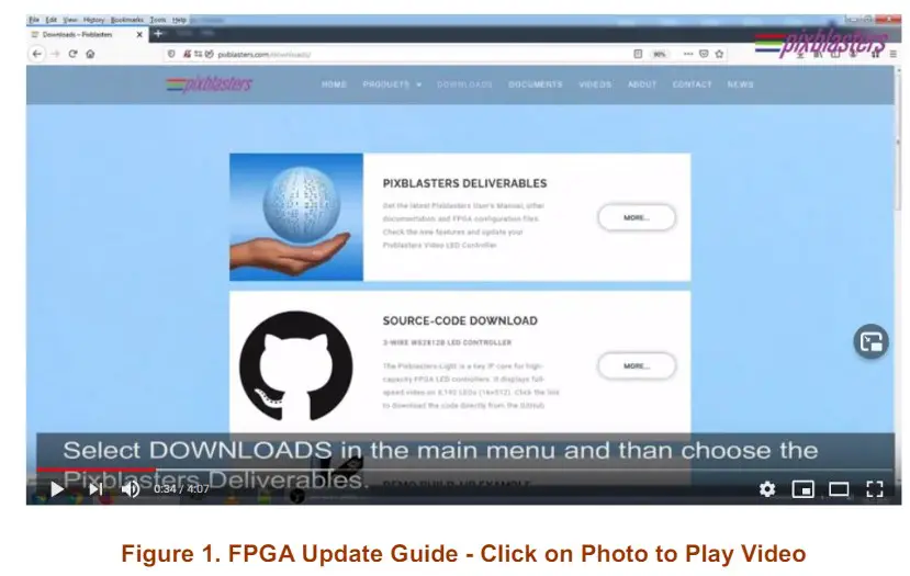 The FPGA update is very simple and can be done within a couple of minutes. It is also permanent, since on-board memory holds up to seven (7) different FPGA configurations. Users can choose the FPGA configuration for their application by on-board DIP switches (Figure 3). Depending on the programmed configurations, the Pixblasters MS1 can be setup in the master or slave mode, to support 3-wire WS2812B-like, 4-wire APA102-like LED strips and WS2812B LED panels.
![]() The DIP switches combination 000 activates the FPGA update configuration and it is not user-programmable. For full explanation, please read the User’s Manual chapter 8.7 Updating FPGA Configuration
The DIP switches combination 000 activates the FPGA update configuration and it is not user-programmable. For full explanation, please read the User’s Manual chapter 8.7 Updating FPGA Configuration
The FPGA update runs on any control computer and any operating system that enables use of a simple serial terminal emulation program. The Pixblasters development team preference is the Tera Term, an open-source and free terminal emulator program: https://ttssh2.osdn.jp/. The requested serial communication parameters are: baud rate 115,200, data 8 bit, no parity, 1 stop bit and no flow control.
Required hardware equipment is also very simple and includes only the control computer, Mini-B USB serial cable and the +5 VDC power supply. Upon the initialization, the control computer and the USB serial cable can be permanently disconnected.
Pixblasters MS1 Controller – Important Terminals
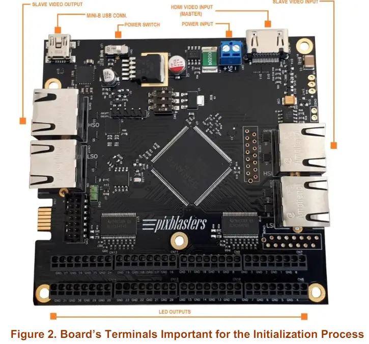
- +5 VDC power supply connects to the blue power input screw wire terminal
- Power switch – the red LED next to the switch is ON when the board is powered
- Mini-B USB connector for serial connection with the control computer
- HDMI video input is the active video input in the Pixblasters MS1 Master configuration
- Slave video input (RJ45 type connector) is the active video input in the Pixblasters MS1 Slave configuration
- Slave video output (RJ45 type connector) is the active video output in both, the Master and the Slave configurations
- 32 LED outputs are placed on eight snap-in connectors (black)
The FPGA Update – Step by Step
- Download the latest FPGA configuration files from http://pixblasters.com/deliverables/
- Set the on-board DIP switches to 000 (Figure 3). This activates the service mode and enables the FPGA update.

- Connect the control computer and the Pixblasters MS1 with the Mini-B USB serial cable.
- Connect the +5 VDC power supply to the blue power terminal on the MS1 controller
- Switch-on the MS1 board with the on-board power switch (the RED LED must be ON)
- Start the serial terminal application on your control computer. Select the proper serial port and setup communication parameters to 115200 8 0 1 0.
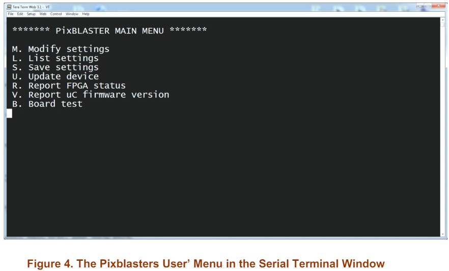
- The Pixblasters User’s Menu should pop-up in the serial terminal window (Figure 4)
- Hit ‘U’ to start the update procedure.
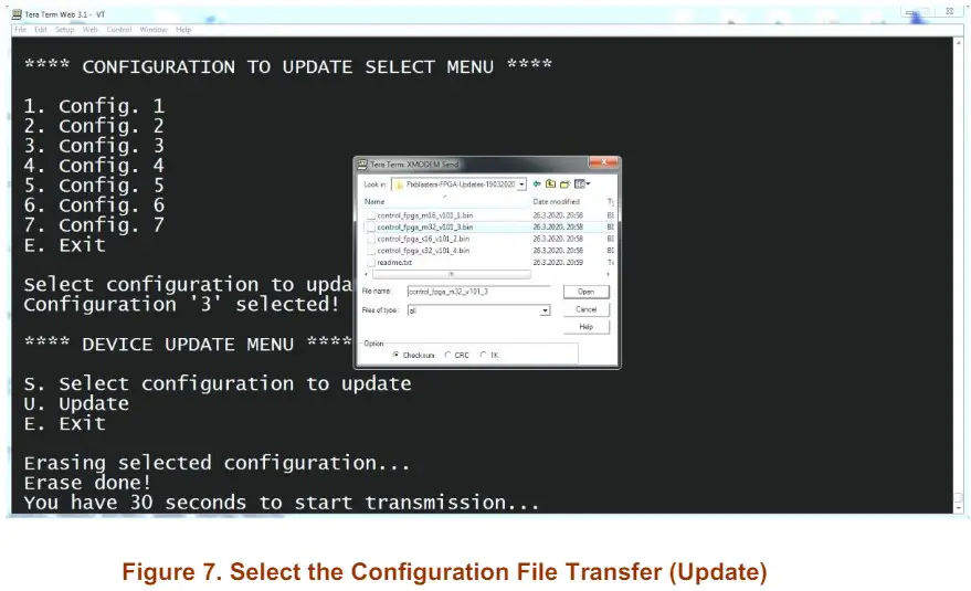
- Hit ‘S’ to open the configuration selector menu (Figure 5)
- Hit ‘3’ to select the FPGA configuration No. 3 for the update (Figure 5)

- The 30 seconds timeframe for the update’s start begins
- Select and transfer to the board the configuration binary file (.BIN) with the FPGA configuration update. In Tera Term you need to select menu File/Transfer/XMODEM/Send
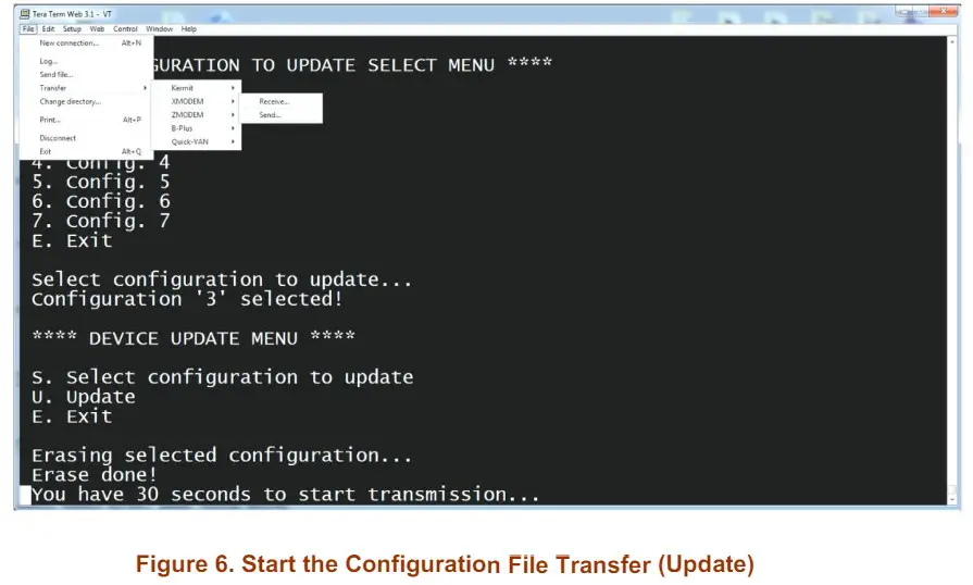
- In the pop-up window find and select the .bin FPGA update file downloaded from our website
- The FPGA update takes about 30-40 seconds (Figure 8).
- At the end of the update, the Device Update Menu (Figure 5) pops-up again. Select ‘E’ to exit.
- The FPGA update is finished and you can start using the new and updated Pixblasters MS1 features.
- To start using the FPGA configuration number 3, please switch off the board and set the DIP switches to 011 position.

The Pixel Mapping Matrix Update – for LED panels only
 The Pixblasters MS1 Video LED Controller requires an additional initialization step for driving WS2812B compatible LED panels. LED panels are usually controlled by the FPGA configuration 5 and must be accompanied by the pixel mapping matrix that describes the structure of the LED panel.
The pixel mapping matrices are provided by Pixblasters, as parts of the FPGA update package.
![]() Depending on the attached LED panel, the user must select the correct .BIN file and program it to the dedicated Configuration 7 by following the steps described in the previous paragraph.
Depending on the attached LED panel, the user must select the correct .BIN file and program it to the dedicated Configuration 7 by following the steps described in the previous paragraph.
| LED Panel Type | Pixel Mapping Matrix File |
| 8×8 | p8x8_deg0.bin |
| 16×16 | p16x16_deg0.bin |
| 32×8 | p32x8_deg0.bin |
| 22×22 | p22x22_deg0.bin |
| 44×11 | p44x11_deg0.bin |
Table 1. Examples of Pixel Mapping Matrix Files for Different LED Panels
Recommendations and Conclusion
Pixblasters FPGA update is optional, very easy and straightforward. For more instructions video clips, please visit: http://pixblasters.com/videos/
Revision History
| Version | Date | Description of Revisions |
| 1 | 02.03.2021. | Initial public release. |
| 2 | 28.05.2024. | Explained programming of the pixel mapping matrix for LED panels. |
APPLICATION NOTE: PAPP003 (v2.0) May 28, 2024
PAPP003 (v2.0) May 2024
www.pixblasters.com
Documents / Resources
 |
pixblasters MS1 Video LED Controller [pdf] User Guide MS1 Video LED Controller, Video LED Controller, LED Controller, Controller |