![]()
J2200A
Optocoupler CTR Module
USER’S GUIDE
April 2022 Version 1.0 Printed in Taiwan
PICOTEST CORP.
8F-1, 286-9, Hsin-Ya Rd., 80673, Kaoshiung, Taiwan
TEL: +886-7-815-7183
FAX: +886-7-815-8312
URL : http://www.picotest.com.tw
Product Overview
In the past, figuring out the optocoupler’s DC/CTR values has always taken a bit of time or has required costly equipment. Now the J2200A can solve these issues.
Product Applications
The J2200A can be used as …
- An IQC tester for identifying real or fake optocoupler units.
- A classifier for factory workers to rank and mark the optocoupler’s DC CTR values.
- A circuit-design tool for engineers and students to match one optocoupler’s DC CTR or Delta CTR value with another.
Product I/O
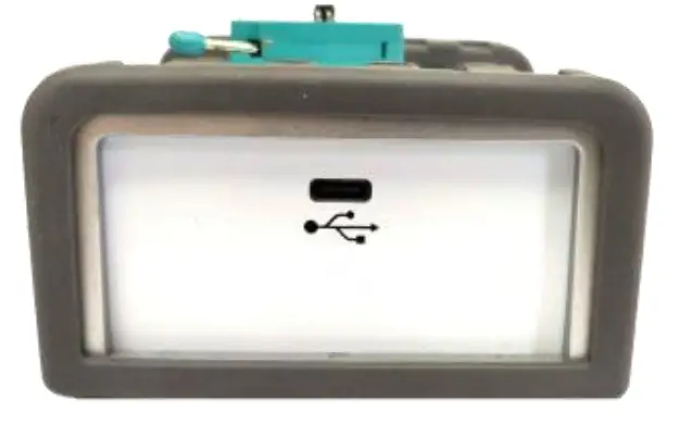
Input Power
Used with the M3522A 6 1/2 DMM, it requires a type-C cable to connect (you can use the M3522A’s front USB plug outputs 5V/0.5A).
Optocoupler Insert Socket
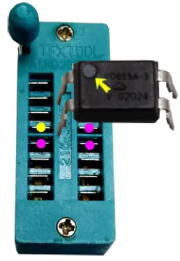
When inserting an optocoupler into the socket, the pin with a black point (yellow arrow) needs to be plugged into the yellow point of the socket. When it’s in place, push the bar down to fasten.
Note1: The hot-plugging for each DUT on J2200A is allowable.

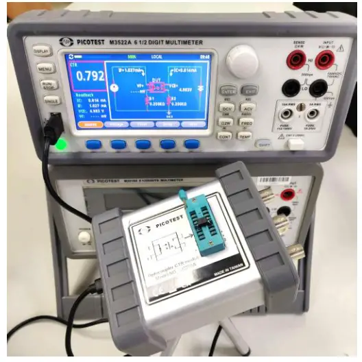
CTR Connection State
When the connection is made, power on your DMM. The overall state will show up like the picture below.
Optional Bode 100 VNA Connections
Besides the M3522A, you have other ways to check CTR values. For example, via Bode 100, connect OSC, CH1, and CH2 to the same ports at 1 2 3 on J2200A (See Figure-1).
M3522A Operation/Setup
Using the Current Range Auto section, you don’t need to set up anything. Just make sure everything is connected correctly to your M3522A and J2200A. Then the display will switch to the CTR mode automatically as shown below.
In the picture, the red frame shows the measured CTR values, and the white frame shows the DUT condition with the variations of IC/IF/VCE/VF.

For the advanced setup, the source IC/IF and voltage-current VCE/VCC is available to set up (Valid Range: 10uA ~ 40mA). There are current ranges you can choose according to your application, such as…
- 1mA: Rsense 1K
- 10mA: Rsense 100
- 100mA: Rsense 10 In addition, to smooth/average the readings, you can set up the counts via entering the Filter section.
![]() Warning
Warning
- To avoid damaging the J2200A, please do not input any external power into the J2200A or DUT.
specifications
Under 20 ~ 40 / USB Power: 5V/0.5A
Output Rating
| Item | min | max |
| VCC | 0.5V | 15V |
| VCE | 0.5V | 15V(i) |
| IF(AutoRange) | 0.05mA | 40mA |
| IF(@1mA ) | 0.05mA | 1.6mA |
| IF(@10mA) | 0.5mA | 16mA |
| IF(@100mA) | 5mA | 40mA |
| IC(AutoRange) | 0.05mA | 40mA |
| IC(@1mA) | 0.05mA | 1.6mA |
| IC(@10mA) | 0.5mA | 16mA |
| IC(@100mA) | 5mA | 40mA |
Programming Accuracy
| Item | % |
| VCC(Setting+Range) | 1%+50mV |
| VCE(Setting+Range) | 1%+50mV |
| IC(Setting+Range) | 0.5%+0.5% |
| IF(Setting+Range) | 0.5%+0.5% |
| IF(Setting+Range) | 0.5%+0.5% |
Read-Back Accuracy
| Item | % |
| VCC(Reading+Range) | 1%+50mV |
| VCE(Reading+Range) | 1%+50mV |
| IC(Reading+Range) | 0.5%+0.5% |
| IF(Reading+Range) | 0.5%+0.5% |
| VF | 50mV |
| CTR | 5% |
| A CTR | 10% |
FRA Port (Typical)
| Item | Value |
| OSC level | <13dBm |
| Usable Bandwidth | 10∼100KHz |
| Modulator Gain(@1mA) | 0.0625mA/V |
| Modulator Gain(@10mA) | 0.625mA/V |
| Modulator Gain(@100mA) | 6.25mA/V |
Note:
(i)VCC = VCE+IC*Rc, VCE<=VCC
※ Note2: The above specifications are subject to change without notice due to design improvements.
Documents / Resources
 |
PICOTEST J2200A Optocoupler CTR Module [pdf] User Guide J2200A, Optocoupler CTR Module, J2200A Optocoupler CTR Module |


