PHOENIX CONTACT IB IL AI 4-EF-PAC Inline Analog Input Terminal

Please be informed that the data shown in this PDF document is generated from our online catalog. Please find the complete data in the user documentation. Our general terms of use for downloads are valid.
Inline, Analog input terminal, Analog inputs: 4, 0 V … 5 V, -5 V … 5 V, 0 V … 10 V, -10 V … 10 V, 0 mA … 20 mA, 4 mA … 20 mA, -20 mA … 20 mA, connection technology: 2-, 3-, 4-conductor, transmission speed in the local bus: 500 kbps, degree of protection: IP20, including Inline connectors and marking fields
Product description
The terminal is designed for use within an Inline station. It is used to acquire analog voltage and current signals.
Advantages
Your advantages
- 4 differential signal inputs
- Connection of sensors in 2-, 3-, and 4-conductor technology
- Current ranges: 0 mA … 20 mA, 4 mA … 20 mA, ±20 mA
- Voltage ranges: 0 V … 10 V, ±10 V, 0 V … 5 V, ±5 V
- The channels are parameterized independently of one another via the bus system
- Parameterization via process data or PCP
- Measured values can be represented in four different formats
- Resolution depends on the representation format and the measuring range
- Process data update of all channels in max. 1 ms
- Sensor supply with channel-specific integrated short-circuit and overload protection
- Bus-synchronous provision of input values with very low jitter (< 10 μs)
Commercial data
- Item number 2878447
- Packing unit 1 pc
- Minimum order quantity 1 pc
- Sales key DR01
- Product key DRI141
- Catalog page Page 136 (C-6-2019)
- GTIN 4017918996376
- Weight per piece (including packing) 252 g
- Weight per piece (excluding packing) 210 g
- Customs tariff number 85389091
- Country of origin DE
Technical data
Dimensions
| Dimensional drawing | 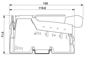 |
| Width | 48.8 mm |
| Height | 135 mm |
| Depth | 71.5 mm |
| Note on dimensions | Housing dimensions |
Notes
Note on application
Note on application Only for industrial use
Utilization restriction
CCCex note Use in potentially explosive areas is not permitted in China.
Interfaces
Inline local bus
- Number of interfaces 2
- Connection method Inline data jumper
- Transmission speed 500 kbps
System properties
Module
| ID code (dec.) | 223 |
| ID code (hex) | DF |
| Length code (hex) | 05 |
| Length code (dec) | 05 |
| Process data channel | 80 bit |
| Input address area | 10 Byte |
| Output address area | 10 Byte |
| Register length | 96 bit |
| Required parameter data | 28 Byte |
| Required configuration data | 4 Byte |
Input data
Analog: General
| Input name | Analog inputs |
| Description of the input | Differential input, including sensor supply (24 V DC) |
| Number of inputs | 4 |
| A/D conversion time | max. 10 µs |
| A/D converter resolution | 16 bit |
| Connection method | Inline shield connector |
| Connection technology | 2-, 3-, 4-conductor |
| Note regarding the connection technology | shielded |
| Current input signal | 0 mA … 20 mA |
| 4 mA … 20 mA | |
| -20 mA … 20 mA | |
| Input resistance current input | typ. 110 Ω |
| Voltage input signal | 0 V … 5 V |
| -5 V … 5 V | |
| 0 V … 10 V | |
| -10 V … 10 V | |
| Input resistance of voltage input | typ. 300 kΩ |
| Data formats | IB IL, IB ST, standardized representation, S7 compatible |
| Limit frequency (3 dB) | 500 Hz |
| Measured value resolution | 16 bits (15 bits + sign bit) |
| Protective circuit | Transient protection; Yes, via arresters |
| Overload protection of the current inputs; electronic |
Product properties
| Product type | I/O component |
| Product family | Inline |
| Type | modular |
| Scope of delivery | including Inline connectors and marking fields |
| Operating mode | Process data mode with 5 words/1 word PCP |
| Diagnostics messages | Failure of the internal I/O supply I/O error message sent to the bus coupler |
| Failure of or insufficient communications power UL I/O error message sent to the bus coupler | |
| I/O error Error message in the process data | |
| User error Error message in the process data |
Insulation characteristics
| Overvoltage category | II (IEC 60664-1, EN 60664-1) |
| Pollution degree | 2 (IEC 60664-1, EN 60664-1) |
Electrical properties
| Maximum power dissipation for nominal condition | 1.4 W |
Potentials: Communications power (UL)
| Supply voltage | 7.5 V DC (via voltage jumper) |
| Current draw | max. 100 mA |
| typ. 85 mA |
Potentials: Supply of analog modules (UANA)
| Supply voltage | 24 V DC (via voltage jumper) |
| Supply voltage range | 19.2 V DC … 30 V DC (including all tolerances, including ripple) |
| Current draw | max. 20 mA |
| typ. 13 mA |
Potentials: Main circuit supply (UM)
| Supply voltage | 24 V DC (via voltage jumper) |
| Supply voltage range | 19.2 V DC … 30 V DC (including all tolerances, including ripple) |
| Current draw | max. 200 mA |
| min. 0 mA (No-load) |
Supply:
| Designation | Sensor supply UiS |
| Supply voltage | 24 V DC (via feed-in from UM) |
| Current consumption | max. 50 mA (per channel) |
Electrical isolation/isolation of the voltage ranges
| Test voltage: 7.5 V supply (bus logic), 24 V supply UANA / I/O | 500 V AC, 50 Hz, 1 min |
| Test voltage: 7.5 V supply (bus logic), 24 V supply UANA / functional ground | 500 V AC, 50 Hz, 1 min |
| Test voltage: I/O/functional ground | 500 V AC, 50 Hz, 1 min |
Connection data
Connection technology
| Connection name | Inline connector |
Conductor connection
| Connection method | Spring-cage connection |
| Conductor cross section rigid | 0.08 mm²…. 1.5 mm² |
| Conductor cross section flexible | 0.08 mm²…. 1.5 mm² |
| Conductor cross section AWG | 28 … 16 |
| Stripping length | 8 mm |
Inline connector
| Connection method | Spring-cage connection |
| Conductor cross section, rigid | 0.08 mm²…. 1.5 mm² |
| Conductor cross section, flexible | 0.08 mm²…. 1.5 mm² |
| Conductor cross section AWG | 28 … 16 |
| Stripping length | 8 mm |
Environmental and real-life conditions
Ambient conditions
| Ambient temperature (operation) | -25 °C … 55 °C |
| Degree of protection | IP20 |
| Air pressure (operation) | 70 kPa … 106 kPa (up to 3000 m above sea level) |
| Air pressure (storage/transport) | 70 kPa … 106 kPa (up to 3000 m above sea level) |
| Ambient temperature (storage/transport) | -25 °C … 85 °C |
| Permissible humidity (operation) | 10 % … 95 % (non-condensing) |
| Permissible humidity (storage/transport) | 10 % … 95 % (non-condensing) |
Standards and regulations
| Protection class | III (IEC 61140, EN 61140, VDE 0140-1) |
Mounting
| Mounting type | DIN rail mounting |
Drawings
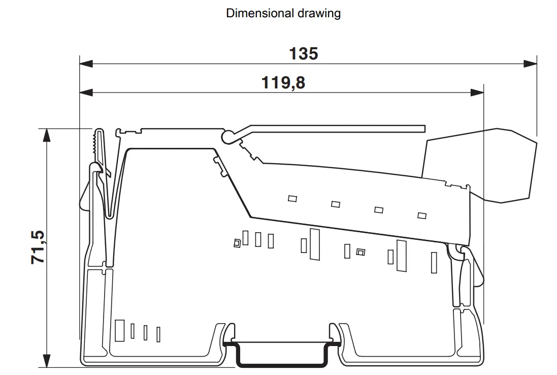
Dimensions (in mm)
Connection diagram

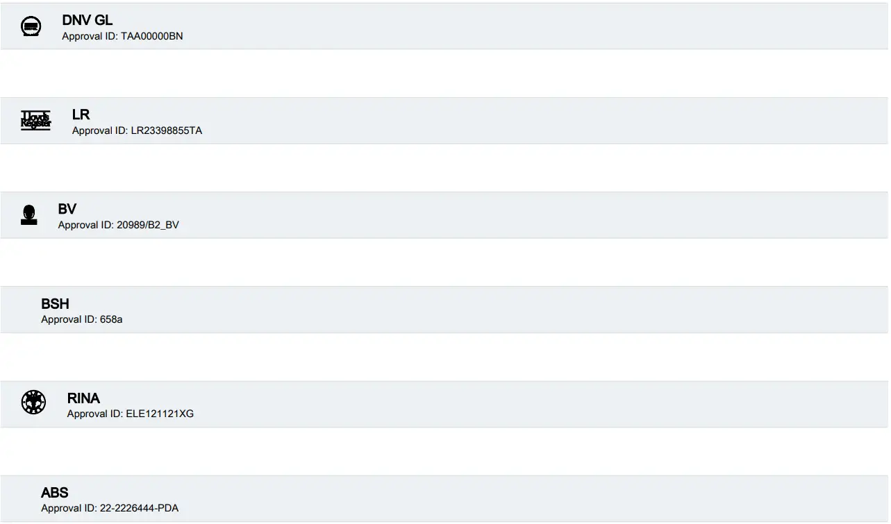
Approvals
To download certificates, visit the product detail page: https://www.phoenixcontact.com/us/products/2878447

Classifications

Environmental product compliance
EU RoHS
- Fulfills EU RoHS substance requirements Yes
- Exemption 7(a), 7(c)-I
China RoHS
- Environment friendly use period (EFUP) EFUP-E
- No hazardous substances above the limits
EU REACH SVHC
- REACH candidate substance (CAS No.) Lead(CAS: 7439-92-1)
- SCIP 65d3ee3f-eeca-4650-b44c-1b47cf964fe2
Contact
- Phoenix Contact 2025 © – all rights reserved
- https://www.phoenixcontact.com
- Phoenix Contact USA
- 586 Fulling Mill Road
- Middletown, PA 17057, United States
- (+717) 944-1300
- info@phoenixcon.com
Downloaded from Arrow.com
FAQ
- Q: Can this module be used in potentially explosive areas?
- A: No, the use of this module in potentially explosive areas is not permitted in China.
- Q: What is the voltage range for the current input signal?
- A: The voltage range for the current input signal is specified as 0 V to 5 V.
Documents / Resources
 |
PHOENIX CONTACT IB IL AI 4-EF-PAC Inline Analog Input Terminal [pdf] Owner's Manual IB IL AI 4-EF-PAC Inline Analog Input Terminal, IB IL AI 4-EF-PAC, Inline Analog Input Terminal, Analog Input Terminal, Input Terminal |