![]() IOLAN SCR226/SRC226
IOLAN SCR226/SRC226
SCR242/SCRC242
SCR258/SCRC258
Hardware Installation Guide
June 2024
Document Part#5500491-10
Revision A1 #.07.25.2024
www.perle.com

Preface
Audience
This guide is for the network or computer technician responsible for installing the Perle IOLANSCR226/SCRC226, SCR242/SCRC242, and SCR258/SCRC258 also referred to as the IOLAN within this document.
Familiarity with the concepts and terminology of Ethernet and local area networks is required.
Purpose
This document describes the hardware and physical characteristics of the Perle IOLAN SCR. It covers hardware features as well as installation and operation of the IOLAN. This document does not cover how to configure your Perle IOLAN. Information to configure your Perle IOLAN SCR can be found in the IOLAN SCR User’s Guide and in the IOLAN SCR CLI Guide on the Perle website and in your IOLAN SCR226/SCRC226, SCR242/SCRC242, and SRC258/SCRC258 Quick Start Guide.
Chapter Overviews
| Main Topics | Description |
| Overview | Components of your IOLAN. |
| Reset / Factory Default / Safe Mode | How to reset the IOLAN to factory defaults or safe mode. |
| Configuring Methods for the IOLAN SCR | Methods to configure the software features for the IOLAN. |
| Appendix A—Technical Specifications | Overall technical specifications including input power and environmental specifications. |
| Appendix B—Cabling and Pin- outs | Cables and connectors used with the IOLAN. |
| Appendix C—Maintaining your IOLAN SCR | Maintenance of your IOLAN. |
| Appendix D—Mechanical | Mechanical drawings showing product dimensions. |
Additional Documentation
| Document | Description |
| IOLAN SCR User’s Guide | User guide explaining how to configure the IOLAN fea- tures using the WebManager applications. New users should use these methods to configure the IOLAN SCR. |
| IOLAN SCR CLI (Command Line Interface) Reference Guide | Command Line Interface Reference Guide using CLI com- mands to configure the IOLAN (this is an advanced way to configure the IOLAN). |
| IOLAN SCR QSG (Quick Start Guide) | Quick Start Guide covers the initial setup of the IOLAN. |
Document Conventions
This document contains the following conventions:
Most text is presented in the typeface used in this paragraph. Other typefaces are used to help you identify certain types of information. The other typefaces are:
Note: Means reader take note: notes contain helpful suggestions.
Caution: Means reader be careful. In this situation, you might perform an action that could result in equipment damage or loss of data.
Warning: IMPORTANT SAFETY INSTRUCTIONS
Means danger. You are in a situation that could cause bodily injury. Before you work on any equipment, be aware of the hazards involved with electrical circuitry and be familiar with standard practices for preventing accidents.
The following warnings and instructions apply:
Limitation of Liability
The information in this manual is subject to change without notice and does not represent a commit-ment on the part of Perle for any and all direct, indirect, special, general, incidental, consequential,punitive or exemplary damages including, but not limited to loss of profits or revenue or anticipated profits or revenue arising out of the use or inability to use any Perle IOLAN even if Perle has been advised or the possibility of such damages or they are foreseeable or for claims by any third party.
Notwithstanding the foregoing, in no event shall Perle aggregate liability arising under or in connection with the Perle product, regardless of the number of events, occurrences, or claims giving rise to liability, be in excess of the price paid by the purchaser for
the Perle product.
Copyright © 2024 Perle.
All rights reserved.
Windows® is a registered trademarks of Microsoft Corporation.
Other trademarks are the property of their respective owners
General cautions and warnings
| 13 | IEC 60417-5041 (2002-10) | Caution, hot surface | |
| 14 | Refer to manual/safety |
Warning: Power sources must be off prior to beginning the power connection steps. Read the installation instructions before you connect the unit to its power source.
Warning: Ensure that the voltage and current ratings of the intended power source are appropriate for the IOAN has indicated on the product label.
Warning: Ensure that the installation and electrical wiring of the equipment is performed by trained and qualified personnel and that the installation complies with all local and national electrical codes.
Warning: If this equipment is used in a manner not specified by the manufacturer, the protection provided by the equipment may be impaired.
Warning: In case of malfunction or damage, no attempts at repair should be made by the user. Do not dismantle this product. In case of malfunction or damage, contact Perle Technical support.
Warning: The unit should be installed in a restricted access location where access can only be gained by service personnel or users who have been instructed about the reasons for the restrictions applied to the location and about any precautions that shall be taken; and access is through the use of a tool or lock and key, or any means of security, and is controlled by the authority responsible for the location.
Class 2 circuit according to the Canadian electrical code, part 1, C22.1
Class 2 circuit according to National Electrical Code, NFPA-70
Limited Power Supply (LPS) according to EN/IEC 60950-1;
Limited-energy circuit according to EN/IEC 61010-1
THE SPECIFICATIONS AND INFORMATION REGARDING THE PRODUCTS IN THIS GUIDE ARE SUBJECT TO CHANGE WITHOUT NOTICE. ALL STATEMENTS, INFORMATION, AND RECOMMENDATIONS IN THIS GUIDE ARE BELIEVED TO BE ACCURATE BUT ARE PRESENTED WITHOUT WARRANTY OF ANY KIND, EXPRESS OR IMPLIED. USERS MUST TAKE FULL RESPONSIBILITY FOR THEIR APPLICATION OF ANY PRODUCTS.
This equipment has been tested and found to comply with the limits for a Class B digital device, pursuant to part 15 of the FCC rules. These limits are designed to provide reasonable protection against harmful interference when the equipment is operated in a commercial environment. This equipment generates, uses, and can radiate radio-frequency energy and, if not installed and used in accordance with this hardware guide may cause harmful interference to radio communications.
Modifications to this product not authorized by Perle could void the FCC approval and negate your authority to operate the product.
Perle reserves the right to make changes without further notice, to any products to improve reliability, function, or design.
Perle, the Perle logo, and are trademarks of Perle.
Copyright ©2024 Perle.
60 Renfrew Drive, Markham, Ontario, L3R 0E1, Canada
All rights reserved. No part of this document may be reproduced or used in any form without written permission from Perle.
Perle reserves the right to make changes without further notice, to any products to improve reliability, function, or design.
Perle, the Perle logo, and IOLAN SCR servers are trademarks of Perle Systems Limited. 60 Renfrew Drive Markham, Ontario
L3R 0E1 Canada
Overview
The IOLAN SCR all in one Serial Console Server and Ethernet router was specifically design for data center full integration deployments. The IOLAN SCR adds full IPv4/IPv6 routing capabilities with support for RIP, OSPF, and BGP protocols and increased security with an integrated firewall supporting zone firewall and two factor authentication. The IOLAN SCR gives you a way to access serial devices remotely from anywhere there is a network connection. For infrastructure management, the Perle IOLAN SCR
will provide the most versatile access to your IT equipment’s serial consoles whether in a large scale data center or remote branch.
What’s in the box
- IOLAN SCR unit
Additional items for each model
- 2 cellular antennas (for cellular models SCRC)
- Dual A/C power with power cables (depends on order)
What you need to supply
Before you can begin, you need to have the following:
- A serial cable(s) to connect serial devices to your SCR unit
- Ethernet CAT5/5e/6 10/100/1000BASE-T cable to connect Ethernet devices to your IOLAN
- SIM card/s (from your cellular provider), if you want to use cellular (C models)
- SFP modules (if you want to use SFP modules)
- Fiber cables (if you are using SFP modules)
Hardware
IOLAN SCR Console/USB Port View (cellular model shown) IOLAN SCR226, SCR242, and SCR258 Serial/Ethernet Port View
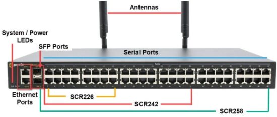
LEDs
| LED Colour/Action | Description | |
| LEDs | ||
| SYS | ||
| Off | No power | |
| Red | Power has been applied | |
| Amber–solid | Kernel is loading | |
| Amber–flashing | System is booting | |
| Green–solid | Normal operation | |
| Green–flashing | No configuration or Safe mode | |
| PWR1 (Power 1) | ||
| Off | No power supplied to PWR1 Dual power is not enabled | |
| Green | Power 1 is On | |
| Yellow | Dual power enabled, power supply 1 is not operational | |
| PWR2 (Power 2) | ||
| Off | No power supplied to PWR2 Dual power is not enabled | |
| Green | Power 2 is On | |
| Yellow | Dual power enabled, power supply 2 is not operational | |
Admin Console Ports
In admin console mode, both the USB port and the RJ45 port provide direct access to the Command Line Interface (CLI) as well as provides statuses, logging, and troubleshooting information. The IOLAN has one RJ45 console port and one USB-C located on the admin/console. The IOLAN can be fully configured and managed from the console ports. Only one console port can be used at a time.
The RJ45 console port is an 8-pin female connector (with DTE pinouts). See RJ45 Console Port Pinout in the cabling section of this guide.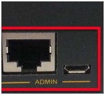
Connecting to the Admin Console port:
- Connect the power, then set the power switches to the On position.
- You can connect the USB console port directly to a PC’s USB port. If using the RJ45 port, you will need to connect to a serial port using an adapter like the Perle 1100300-10, RJ45 to DB-9 adapter.
- Connect an RJ45 cable directly from the IOLAN to the COM port on your PC. See Appendix B— Cabling and Pin-outs for cabling requirements. A serial to USB converter may also be used.
- On the PC, select Choose Start-> Control Panel-> Hardware and Sound or equivalent on the Windows Operating System you are using. The exact procedure may vary depending on the version of Windows you are using.
- Click the Hardware tab and choose Device Manager, Expand the Ports (COM & LPT) section.
This will expand the drop down to show the number of com ports on your system. Connect the cable to one of these COM ports (probably COM1 or COM2. - Start a terminal emulation program (such as Putty or SecureCRT) on the COM port where you have connected the cable to the PC.
- Configure this COM port within the terminal emulation program with the following parameters:
• 9600 baud
• 8 data bits
• 1 stop bit
• No parity
• None (flow control) - Press the Enter key on the keyboard and the login prompt will display.
Connecting Serial Devices
Connect serial devices using a straight through serial cables. Serial devices can be connected to either the RJ-45 ports or the USB ports. See Appendix B—Cabling and Pin-outs for cabling pinouts.
Connecting to the USB ports
The IOLAN USB ports can connect storage devices such as USB flash drives and USB serial devices.
Connecting Ethernet Devices
The Ethernet RJ45 ports provide the standard Ethernet interface speeds of 10/100/1000 Mbps through twisted pair (UTP) cables of up to 100 meters (328ft) in length. By default all of the 10/100/1000 ports will automatically set themselves up to match the speeds of all attached devices. If auto negotiation is not supported by one or more attached devices, the ports can be configured to operate at fixed speeds and duplex settings. Once a link has been established, the LED will indicate whether you have a 10, 100, or 1000 Mbps link on the Ethernet port. See Ethernet Link Status.
Note: Cat5e/Cat6 cables are recommended for 1000 Mbps connections.
Ethernet Ports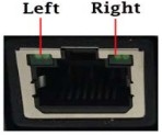
Ethernet Link Status
| Speed | Colour | Side | Description |
| 1000 Mbps | Green | Left | Flashes with activity |
| 100 Mbps | Green Yellow | Left Right | Flashes with activity Flashes with activity |
| 10 Mbps | Yellow | Left | Flashes with activity |
| Off | None | No LAN connection |
SFP Ports
Each SFP connector has a single green LED.
- ON for link up
Flashes with Link activity
Connecting the Antennas
- Connect one cellular antenna (Main) to the SMA connector on the right. Then connect the second antenna to the (Diversity) SMA connector on the left. It is recommended that both the Main and Diversity antennas are connected, the Main antenna connection is always required.

- When attaching the antennas to the SMA connectors, line up the inner hole within the antenna, then slide onto the pin encased in the connector on the IOLAN, gently push to connect, then turn only the securing ring and not the antenna to secure it to the IOLAN.

Note:
When attaching the antennas to the SMA connectors hand tighten only (do not use tools to tighten (maximum torque is 7Kgf-cm/1.1 N-m(10 in-lb).
Inserting the SIM card
The IOLAN SCR comes with two SIM slots for mini-SIM (2FF) card/s.
- Using your Phillips screwdriver, removed the screw from the panel covering the SIM slot. Gently pry the cover loose from the opening.
- Align the SIM card/s so that the SIM card slides into the SIM card slot with the circuit board side facing the PCB. The SIM card has a notched corner for orientation and the SIM card can only be inserted the correct way. You will hear an audible click when the SIM is inserted correctly.
- Align the SIM cover plate and secure the plate with the screw.
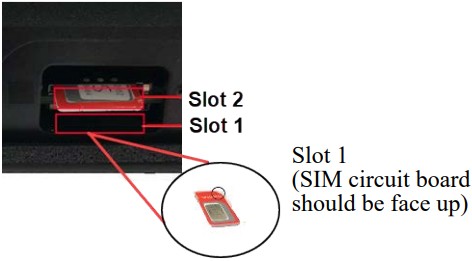
Note:
Do not force the SIM card in or you may damage the card or your IOLAN SCR.
Power Switches
Only one power supply is needed to power the SCR. The secondary power can be used for backup power redundancy. 
Reset / Factory Default / Safe Mode
The reset button provides multiple functions depending on when the reset button is pressed and the press duration. Any small object, such as a paper clip, can be used to press the reset button; however, you should not use excessive force on this button.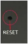 The table below shows how the reset button can be used to accomplish the functions below.
| Mode | Description | LEDs | Function |
| Restart | Press and release the Reset button when the IOLAN is running | System LED will go solid Red, then solid green, changing to flashing orange until the IOLAN is finish the reboot. | Reboots. All configuration and files will remain the same. |
| Factory Default | While the IOLAN is booted and running, press Reset and hold the Reset button until all the LEDs go Red, then release | All LEDs flash Red, unit then reboots into Factory default mode. System LED flashes Green while in factory default mode |
Reboots and resets the configuration to the Perle factory default configuration. All configuration, User IDs, passwords, Virtual Machines, Containers, and security certificates are deleted. • The IOLAN will be in Fast Setup mode with the console ports reverted back to the baud rate of 9600 |
| DHCP/BOOTP (ZTP mode) |
The IOLAN must be in Factory Default mode. When the IOLAN is in factory default mode, press and hold the reset button for 5 seconds | All LEDs will flash Red, then release the reset button | Reboots the IOLAN into Fast setup DHCP/BOOTP (ZTP mode) running config will be copied to startup configuration IOLAN sends out DHCP client requests until it get a DHCP offer |
| Safe Mode | Press the Reset button while powering up, holding the Reset button until all the System LED turns Red, then release, the unit will continue to boot | SYS LED continues to flash green after the unit has rebooted, indicating the unit has no configuration | • Saves the startup config • Boots with no config file • Allows you to do setup mode • console ports reverts back to baud rate 9600 |
Configuring Methods for the IOLAN SCR
The IOLAN can be configured, operated, and monitored using any of the following methods. See the
IOLAN SCR User’s Guide for more details on these methods.
Setting up the SCR for the First Time
The IOLAN can be initially set up using DHCP (ZTP Mode) or via the Fast setup method using an Ethernet or console connection. See the IOLAN Quick Start Guide for more details on these methods.
Option 1—DHCP Mode
Your IOLAN is in factory default mode with the DHCP client enabled on all the up-link Ethernet ports. Connect one of your up-link ports to your network to allow it access to your DHCP server. The DHCP server can now provide IP information to the IOLAN and, optionally, a full configuration file and/or firmware image. If the IOLAN cannot connect to the DHCP server in approximately 10 seconds after the IOLAN has fully booted, it will revert to a configuration with all up-links bridged to a 192.168.0.x subnet with the IOLAN assigned to the 192.168.0.1 IP address. At this point, you can use a browser on a PC which is on the 192.168.0.x network to access the IOLAN. You can HTTP/HTTPS to 192.168.0.1 to access Fast Setup mode.
To set an IP static address.
- Within your PC’s Window’s operating system or equivalent, select Control Panel, then >Network and Internet >Network Sharing Center >Ethernet >Properties > Internet Protocol Version 4 (TCP/IPv4), and set your PC address to 192.168.0.2/255.255.255.0 then click Ok.
- When the Power LED is flashing green, use a web browser and enter http://192.168.0.1 to access your IOLAN
Option 2—Console
Connect a terminal to either the RJ45 or USB console port of the IOLAN. Ensure your terminal is set to 9600 baud, 8 bits, no parity, one stop bit, and no flow control. Press “Enter” on the terminal, and you should now see the Fast Setup prompt.If using a web browser, the following screen appears.
If you select Get Started, fill in the required fields, apply the changes, then save and exit. The configuration changes will be immediately applied to the IOLAN. You can now access your IOLAN’s complete configuration using your supplied credentials from the
WebManager.
If you select See Options, the following screen appears.
The third option, “Enable IOLAN configuration via DHCP/BOOTP (ZTP), and reboot,” will cause the IOLAN to reboot. After the software is fully loaded, the up-link ports will be in DHCP client mode and will remain in this mode indefinitely.
WebManager
The Perle WebManager is an embedded Web based application that provides an easy to use a browser interface for managing the IOLAN. This interface provides the ability to configure and manage the IOLAN through any standard desktop web browser.
CLI
A text-based Command Line Interface based on industry standard syntax and structure. The CLI can be accessed from the console port. Once a valid IP address is configured on the IOLAN, you can Telnet or SSH to access the IOLAN for administration purposes.
See the IOLAN SCR Command Line Interface Reference Guide for more information.
SNMP
The IOLAN can be monitored with an SNMP monitoring tool.
RESTful API
The IOLAN can be monitored, controlled, and configured using the IOLAN’s built-in industry standard RESTful API interface. See the SCR User’s Guide for more details to use this method.
Appendix A—Technical Specifications
| Technical Specifications—SCR226/SCRC226, SCR242/SCRC242, SCR258/SCRC258 | |
| Power Supply | Dual AC power supplies (with passive cooling) |
| Nominal Input voltage | 110/230v AC |
| Input Voltage Range | 100-240 VAC, 47-63 Hz |
| Interfaces | |
| RJ45 RS232 Serial | 16, 32, 48 ports |
| Ethernet Uplink Ports | 2 Ethernet 10/100/1000 Up to 100 meters (328 ft.) Auto-negotiation Auto-MDI/MDIX Ethernet isolation 1500 V |
| USB | 8—USB 2.0 |
| Console Ports | 1 RS-232 RJ45 Console Admin Port 1 USB-C connector Console Admin Port |
| Ethernet Uplink ports—Small Form Factor Pluggable (SFPs) slots | Empty SFP receiver ports 2—SFP modules (speeds supported) • 1 Gbps fiber • 2.5 Gbps fiber • 5.0 Gbps • 10 Gbps • 10/100/1000 SGMII copper • USXGMII |
| Cellular Antennas | Frequency Range: 704-902-928-960/1427.9-1575.42/1710- 2170/2400-2480-2690MHz Gain: 3 dBi Impedance: 50 ohm Voltage Standing Wave Ratio: <3.0 (typical) Radiation: Omni-Directional Connector: SMA Male (Swivel) Dimensions: 135.6 x 20.1 mm / 5.34 x 0.8 in |
| Standards | |
| Environmental Specifications | |
| Operating Temperature Ranges | 0°C to 50°C (32°F to 122°F) |
| Storage Temperature | -40°C to 85°C (-40°F to 185°F) |
| Operating Humidity Range | 5% to 95% non-condensing |
| Storage Humidity Range | 5% to 95% non-condensing |
| Operating Altitude | Up to 3,048 meters (10,000 feet) |
| Case | SECC Zinc plated sheet metal (1 mm) |
| Ingress Protection Rating | IP30 |
| Standards and Certifications | |
| Emissions | FCC 47 Part 15 Subpart B Class A or better ICES-003 (Canada) EN55011(CISPR11) EN55032 (CISPR32) EN61000-3-2 Limits for Harmonic Current Emissions EN61000-3-3 Limits of Voltage Fluctuations and Flicker |
| Immunity | EN61000-4-2 (ESD): Contact: EN 61000-4-3 (RS): EN 61000-4-4 (EFT): EN61000-4-5 (Surge): EN 61000-4-6 (CS): EN 61000-4-8 (PFMF): EN 61000-4.9 (PMF) EN 61000-4-11 |
| Safety | UL/ULC/EN 62368-1 (previously 60950-1) CAN/CSA-C22.2 No. 62368-1 |
| Cellular/Telecom Regulatory Approvals | FCC/ICES, RED, PTCRB/CTIA, CE |
| Carrier/Telcom Regulatory Approval | Verizon, AT&T, T-Mobile (Wholesale and Business) |
| Cellular Radio | EN 301 489-1 (ElectroMagnetic Compatibility (EMC) standard for radio equipment and services) EN 301 489-17 (ElectroMagnetic Compatibility (EMC) standard for radio equipment and services) EN 301 908-1 (Radiated emissions RF control and monitoring) EN 301 908-2 (RF conducted) EN 301 908-13 (RF Conducted) EN 62311 (Human exposure restrictions for radio frequency electromagnetic fields) |
| Other | Reach, RoHS and WEEE compliant |
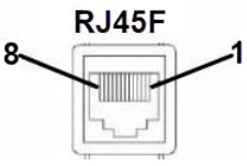
Appendix B—Cabling and Pin-outs
RJ45 Serial Connector Pin-out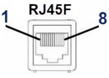 Connect devices, workstations, servers or routers using a straight through serial cable.
| Pin# | Signal | Direction |
| 1 | CTS | IN |
| 2 | DSR | IN |
| 3 | RX | IN |
| 4 | GND | |
| 5 | GND | |
| 6 | TX | OUT |
| 7 | DTR | OUT |
| 8 | RTS | OUT |
The following table shows the RJ45 serial port pin-out when port is configured as “Straight” mode.
| Pin# | Signal | Direction |
| 1 | CTS | OUT |
| 2 | DSR | OUT |
| 3 | RX | IN |
| 4 | GND | |
| 5 | NOT USED | |
| 6 | TX | OUT |
| 7 | DTR | IN |
| 8 | RTS | IN |
The following table shows the RJ45 serial port pin-out when port is configured as “Rolled” mode.
| Pin# | Signal | Direction |
| 1 | RTS | OUT |
| 2 | DTR | OUT |
| 3 | TX | OUT |
| 4 | GND | |
| 5 | DCD | IN |
| 6 | RX | IN |
| 7 | DSR | IN |
| 8 | CTS | IN |
RJ45 Console Port Pin-out
| Pin# | Signal | Direction |
| 1 | RTS | OUT |
| 2 | DTR | OUT |
| 3 | TX | OUT |
| 4 | GND | |
| 5 | GND | |
| 6 | RX | IN |
| 7 | DSR | IN |
| 8 | CTS | IN |
RJ45 to RJ45 Cable Pin-out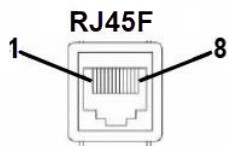
Pinout
1 —————->1
2 —————->2
3 —————->3
4 —————->4
5 —————->5
6 —————->6
7 —————->7
8 —————->8
Appendix C—Maintaining your IOLAN SCR
Ensure there is clearance of 50.8mm (2 inches) on all sides of the IOLAN to provide proper airflow through the unit
- Do not use solvents or cleaning agents on this unit
- Keep vent holes clear of debris
- If case gets dirty wipe with a dry cloth
- Ensure all cables are in working condition
Appendix D—Mechanical
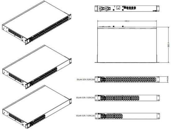
![]()
Documents / Resources
 |
Perle SRC226 Hardware Data Control in Device Servers [pdf] Installation Guide SRC226 Hardware Data Control in Device Servers, SRC226, Hardware Data Control in Device Servers, Data Control in Device Servers, Device Servers, Servers |