Panasonic RX-CS730 Portable Stereo Component System

Colour I (K) ….. Black Type
Area
| Suffix for Model No. | Area | Colour |
| (GU) | Asia, Latin America, Middle East and Africa. | (K) |
| (GC) | Saudi Arabia, Kuwait, Singapore, Malaysia. |
| TAPE SECTION: SG20 MECHANISM | SERIES | ||
Specifications |
|||
| ■ RADIO
Frequency range |
GENERAL
Power requirement |
||
| FM | 88 – 108 MHz | AC | 110-127 V / 220-240 V, 50 / 60 Hz |
| MW | 530 – 1605 MHz | Power consumption : 17 W | |
| SW1 | 2.3 – 7.0 MHz | Battery | 12 V (Eight R20 / LR20, D, UM-1 batteries) |
| SW2 | 7.0 – 22.0 MHz | ■ Do not use rechargeable type batteries. | |
| Intermediate frequency | DC IN | 12 – 13.2 V | |
| FM | 10.7 MHz | Power output | 90 W …PMPO |
| AM Sensitivity | 455 kHz | Speakers | 27 W … RMS ( max. )
2 Woofers ; 12 cm |
| FM | 17 dB/ 50 mW | 2 Tweeters ; 1.5 cm | |
| MW | 54 dB/ 50 mW | Jacks | |
| SW1 | 35 dB/ 50 mW | Output | SPEAKERS : 8 Q |
| SW2 | 17 dB/ 50 mW | Headphones; 32Q |
TAPE RECORDER
- Track system 4 track, 2 channel, stereo
- Recording system AC bias
- Erasing system Magnet
- Monitor system Variable sound monitor
- Frequency range Normal 60 -14000 Hz
- Dimensions ( WxHxD) 581 x 255 x 221 mm
- Main unit ; 261 x 255 x 221 mm Speaker box ; 169 x 224 x 204 mm
- Weight 4.8 kg without batteries
Notes:
- Specifications are subject to change without notice.
- Weight and dimensions are approximate.
WARNING
This service information is designed for experience repair technicians only and is not designed for use by the general public. It does not contain warnings or cautions to advise non-technical individuals of potential dangers in attempting to service a product. Products powered by electricity should be serviced or repaired only by experienced professional technicians. Any attempt to service or repair the product or products dealt with in this service information by anyone else could result in serious injury or death.
BEFORE USE
[FOR (GC) area]
- Be sure to disconnect the mains cord before adjusting the voltage selector.
- Use a minus(-) screwdriver to set the voltage selector (on the rear panel) to the voltage setting for the area in which the unit will be used. (If the power supply in your area is 117V or 120V, set to the “127V” position.)
Note that this unit will be seriously damaged if this setting is not made correctly. (There is no voltage selector for some countries; the correct voltage is already set.)
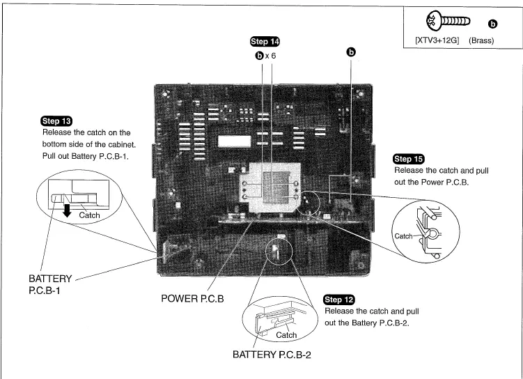
Operation Checks
ATTENTION SERVICER II Some chassis component may have shape edges. Be careful when disassembling and servicing.
- This section describes procedures for checking the operation of the major printed circuit boards and replacing the main components.
- For reassembly after operation checks or replacement, reverse the respective procedures.
Special reassembly procedures are described only when required. - Select items from the following index when checks or replacement are required.
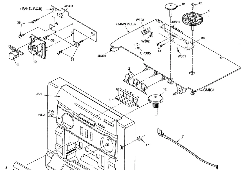
Disassembly Of The Front Cabinet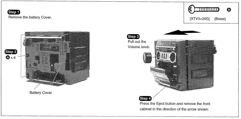
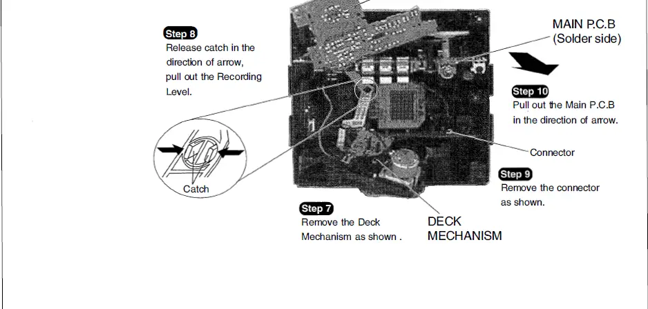
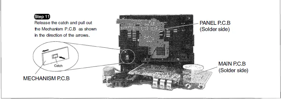
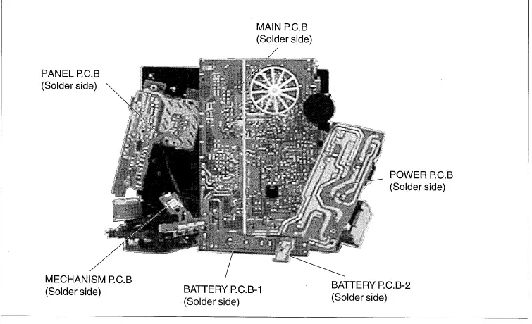
Checking Procedure For Main, Panel, Mechanism And Power P.C.B.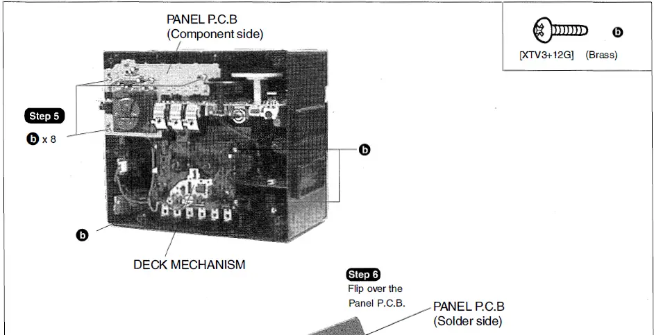
Measurements and Adjustments
Tuner Section
ALIGNMENT INSTRUCTIONS
| READ CAREFULLY | BEFORE | ATTEMPTING ALIGNMENT | |
| 1. Set
2. Set 3. Set 4. Set |
|
|
|
| • AM – IF ALIGNMENT | |||||
| SIGNAL GENERATOR or SWEEP GENERATOR | RADIO DIAL SETTING | INDICATOR (ELECTRONIC VOLTMETER or OSCILLOSCOPE) | ADJUSTMENT(Shown in Fig.1) | REMARKS | |
| CONNECTIONS | FREQUENCY | ||||
| Fashion a loop of several turns of wire and radiate signal into loop of receiver. | 455 kHz30% Mod.at 400Hz | Point of non- interference.(on/ about 600kHz) | Headphone Jack (32Q)( Fabricate the plug as show o )in Fig.2 and then connect the lead wires of the plug to the measuring instrument. | T2(AM IFT) | Adjust for maximum output. |
| • MW- RF ALIGNMENT | |||||
| II | (GU)…. 511 kHz(GC)…. 514 kHz± 3 kHz | Tuning capacitor fully closed. | II | L8(MW OSC. Coil) | Adjust for maximum output. |
| II | (GU)…. 1650 kHz(GC)…. 1639 kHz± 5 kHz | Tuning capacitor fully opened. | II | CT3(MW ANT. Trimmer) | Adjust for maximum output. |
| II | 550 kHz | Tune to signal | II | [*1] L3-1 (MW ANT. Coil | Adjust for maximum output. Adjust L3-1 by moving coil bobbin along the ferrite core. |
| II | 1500 kHz | Tune to signal | II | CT2(MW ANT. Trimmer) | Adjust for maximum output. |
| [*1] Fix antenna coil with wax after completing alignment. | |||||
| • SW1 – RF ALIGNMENT | |||||
| II | 2.249 MHz | Tuning capacitor fully closed. | II | L9(SW1 OSC. Coil) | Adjust for maximum output. |
| II | 7.231 MHz | Tuning capacitor fully opened. | II | VC1-3 (SW1 ANT. VC1) | Adjust for maximum output. |
| II | 2.3 MHz | Tune to signal | II | [*1] L3-2 (SW1 ANT. Coil) | Adjust for maximum output. Adjust L3-2 by moving coil bobbin along the ferrite core. |
| II | 7.0 MHz | Tune to signal | II | VC1-4 (SW1 ANT. VC1) | Adjust for maximum output. |
| [*1] Fix antenna coil with wax after completing alignment. | |||||
| • SW2 – RF ALIGNMENTSIGNAL GENERATOR or SWEEP GENERATOR | RADIO DIAL SETTING | INDICATOR (ELECTRONIC VOLTMETER or OSCILLOSCOPE) | ADJUSTMENT(Shown in Fig.1) | REMARKS | |
| CONNECTIONS | FREQUENCY | ||||
| Connect to test point rnn through ceramic capacitor (10pF).Negative side to test point ii;FJ. | 6.84 MHz | Tuning capacitor fully closed. | Headphone Jack (32Q) ( Fabio, the plug as shown ) in Fig.2 and then connect the lead wires of the plug to the measuring instrument. | L10(SW2 OSC. Coil) | Adjust for maximum output. |
| 22.80 MHz | Tuning capacitor fully opened. | II | CTS(SW2 OSC. Trimmer) | Adjust for maximum output. | |
| 7.0 MHz | Tune to signal | II | L7(SW2 ANT. Coil) | Adjust for maximum output. | |
| • FM – IF ALIGNMENT | |||||
| Connect to test point ii;D through ceramic capacitor. Negative side to test point i:ctl. | 10.7 MHz (Sweep) | Point of non- interference.(on/ about 90MHz) | Connect vert. amp. of scope to test point iiE. Negative side to test point li;E . | T1(FM 1st IFT) | Waveform is shown in Fig. 3. |
| II | II | II | II | T3(FM 2nd IFT) | Waveform is shown in Fig. 4. |
| • FM – RF ALIGNMENT | |||||
| Connect to test point iGil through Fumy antenna. Negative side to test point 1CtJ . | (GU)… 86.2 MHz(GC) 87.35 MHz± 50kHz | Variable capacitor fully closed. | Headphone Jack (32Q)( Fabcioato the plug as shown ) in Fig.2 and then connect the lead wires of the plug to the measuring instrument. | L2(FM OSC. Coil) | Adjust for maximum output. [ *2] |
| (GU)… 109.2 MHz(GC)… 108.3 MHz± 70 kHz | Variable capacitor fully opened. | II | VC1-1(FM OSC. VC1) | II | |
| 106 MHz | Tune to signal | II | VC1-2(FM ANT. VC1) | Adjust for maximum output. | |
| [ *2 ] three output responses will be present; proper tuning is the center frequency. | |||||
Cassette Deck Section
ALIGNMENT INSTRUCTIONS
READ CAREFULLY BEFORE ATTEMPTING ALIGNMENT
Measuring Instruments
Digital frequency counter
Measuring Conditions
- Make sure the heads are clean.
- Make sure the capstan and pressure rollers are clean.
Test Tape
Tape speed adjustment ( 3 kHz, – 10 dB) : QZZCWAT
Note : No Azimuth Head Alignment is required due to Aztec Head is used in the cassette mechanism.
TAPE SPEED ALIGNMENT
| TEST TAPE | EQUIPMENT CONNECTION ELECTRONIC COUNTER | ADJUSTMENT | SPEC.IFICATION | REMARKS | |
| Headphone Jack (32Q) |
|
||||
| QZZCWAT | ( Fabcioato the plug ,s shown ) in Fig.2 and then connect the lead wires of the plug to the | Motor VR(As shown in Fig. 5) | 3000 ± 90 Hz | ||
| measuring instrument. | |||||
| 1 | I | ||||
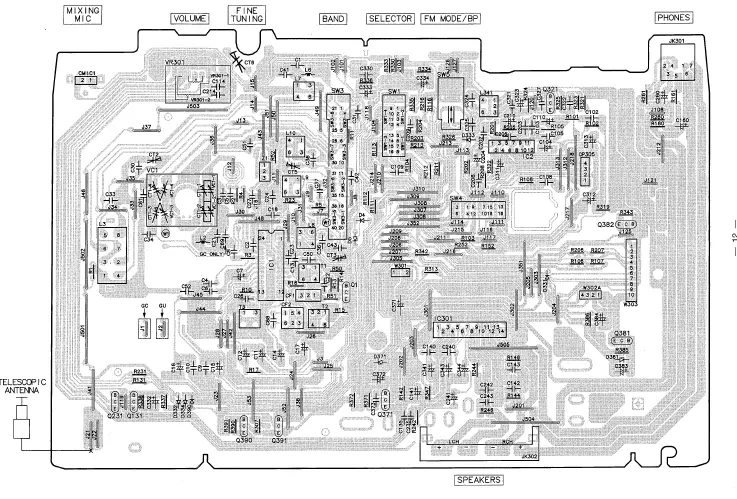
ALIGNMENT POINTS 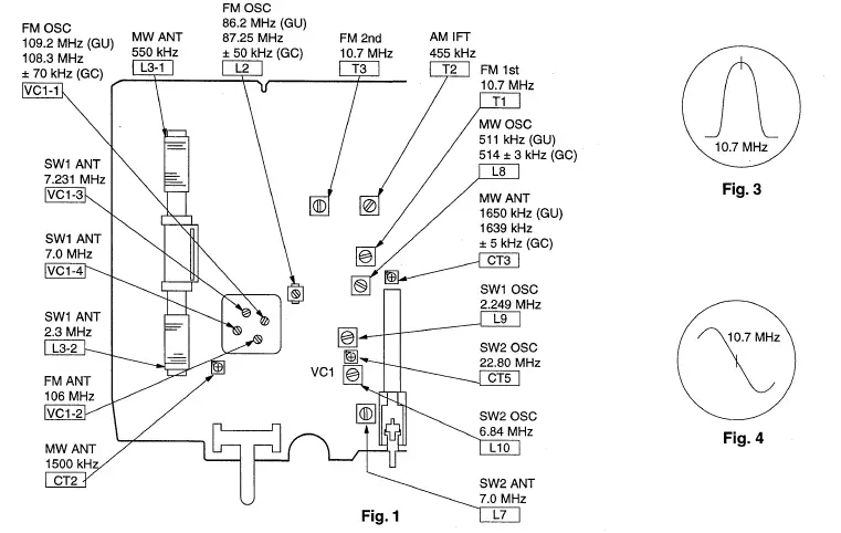
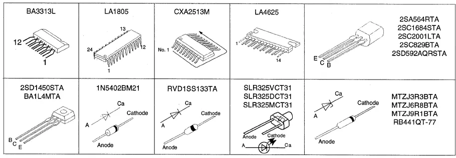
 Terminal Guide of IC1s , Transistors and Diodes
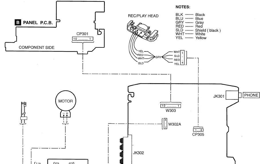
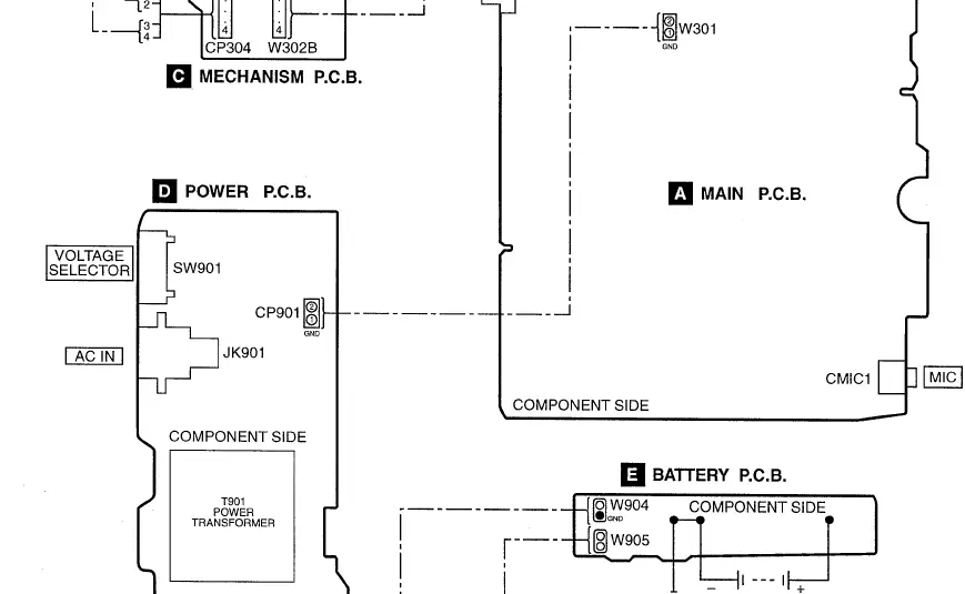
Wiring Connection Diagram
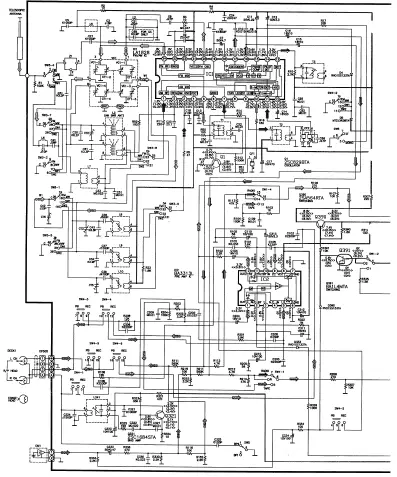
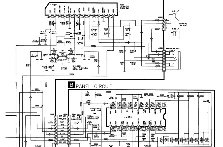
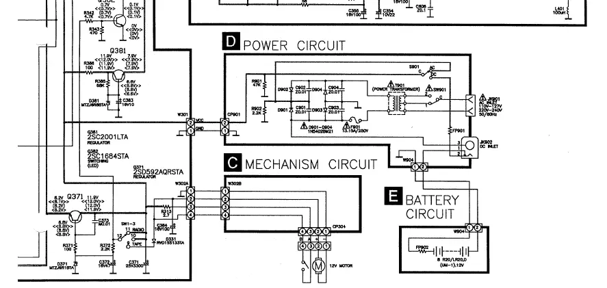
Schematic Diagram
(All schematic diagrams may be modified at any time with the development of new technology) Note:
- S352 Preset equalizer switch
- S353 Preset equalizer switch
- S354 Preset equalizer switch
- S355 Preset equalizer switch
- 5356 Preset equalizer switch
- SW1 SELECTOR switch
- • SW3 BAND select switch switch
- SW4 FM MODE/BP switch
- svml Voyage selector switch
- R301 Volume control VR.
Battery current :
- Vol. min. . …. 390 mA (FM) 390 mA (AM) 458 mA {TAPE)
- Vol. max …… 683 mA (FM) 685 mA (AM) 872 mA {TAPE)
Measurement Instruction
- AM : 74 dB/m, 30% Mod
- FM : 60 dB/m , 30% Mod.
- TAPE: 315Hz ,0dB
Signal line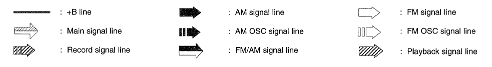
The voltage value and waveforms are the reference voltage of this unit measured by DC electronic voltmeter (high impedance) and oscilloscope on the basis of chassis.
Accordingly, there may arise some error in voltage values and waveforms depending upon the internal impedance of the tester or the measuring unit.
- ( ) ….. AM,
- ….. FM
- <->No mark ….. Playback position,
- << >> ….. Record position
Importance safety notice:
Components identified by ![]() mark have special characteristics important for safety. Furthermore, special parts which have purposes of fire-retardant (resistors), high-quality sound (capacitors), low-noise (resistors), etc. are used. When replacing any of components, be sure to use only manufacturer’s specified parts shown in the parts list.
mark have special characteristics important for safety. Furthermore, special parts which have purposes of fire-retardant (resistors), high-quality sound (capacitors), low-noise (resistors), etc. are used. When replacing any of components, be sure to use only manufacturer’s specified parts shown in the parts list.
Caution!
IC, LSI and VLSI are sensitive to static electricity.
- Secondary trouble can be prevented by taking care during repair.
- Cover the parts boxes made of plastics with aluminium foil.
- Ground the soldering iron.
- Do not touch the pins of IC, LSI or VLSI with fingers directly.
- Put a conductive mat on the work table.
MAIN CIRCUIT
Printed Circuit Board
MAIN P.C.B. (REPX0153A … GC) (REPX0153 … GU)
- C MECHANISM P.C.B. (REPX0153A … GC) (REPX0153 … GU)
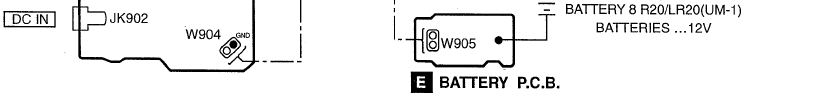
- D BATTERY P.C.B. (REPX0154)
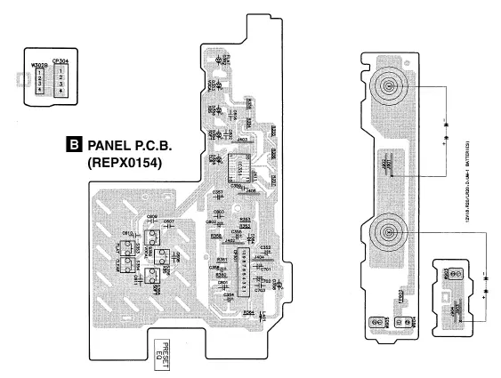 POWER P.C.B. (REPX0154)
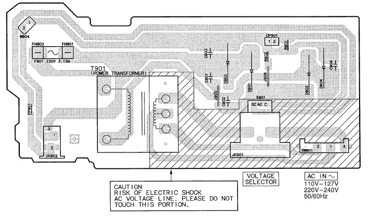 Cabinet Parts Location
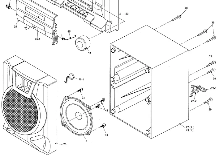
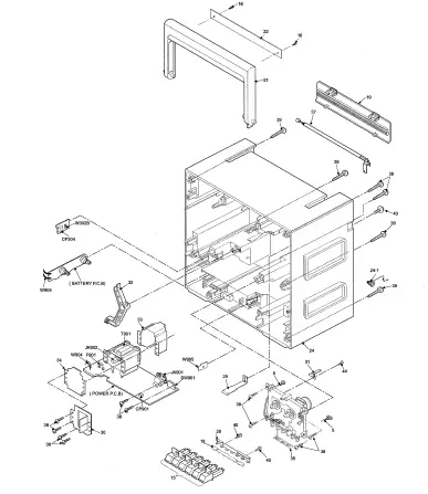
Mechanism Parts Location ( RAA0937 )
Note : Refer to Parts List (Cassette Deck) on 19—20. 

Replacement Parts List
Notes:
- Important safety notice :
- Components identified by
 mark have special characteristics important for safety.
 - Furthermore, special parts which have purposes of fire-retardant (resistors), high-quality sound (capacitors), low-noise (resistors), etc. are used. When replacing any of components, be sure to use only manufacturer’s specified parts shown in the parts list.
- The “SF” mark denotes the standard parts.
- [M] in Remarks column indicates parts that are supplied by MESA.
| Ref No. | Part No. | Part Name & Description | Remarks | Ref No. | Part No. | Part Name & Description | Remarks | Ref No. | Part No. | Part Name & Description | Remarks |
| CABINET AND CHASSIS | 30 | RMAX0041 | METAL BRACKET | [Ml | 123 | RML0073-1 | AS PROTECT LEVER | [Ml | |||
| 31 | RMC0046 | RECORD SPRING | [Ml | 124 | RML0074 | IDLER LEVER | [Ml | ||||
| 1 | RAS12P06-H | SPEAKER WOOFER | [Ml | 32 | RMLX0013 | RECORDING LEVER | [Ml | 125 | RML0076 | EJECT SELECTION LEVEL | [Ml |
| 2 | RBD562WA-S | SELECTOR KNOB | [Ml | 33 | RMVX0036 | TRANS. SHIELD PLATE | [Ml | 126 | RML0077 | LOCK PLATE | [Ml |
| 3 | RDG0183-L | DAMPER GEAR | [Ml | 34 | RMVX0037 | TRANS. TOP SHIELD | [Ml | 127 | RML0078 | FUNCTION PLATE | [Ml |
| 4 | RDGX0011 | VARICON GEAR | [M] | 35 | RMXX0004 | SPACER | [Ml | 128 | XTN2+4F | EARTH LUG SCREW | [Ml |
| 5 | REXX0117-1 | MOTOR WIRE | [Ml | 36 | RMYX0033 | HEAT SINK | [Ml | ·129 | RML0081-1 | RECORD SAFETY LEVER | [Ml |
| 6 | REXX0187 | TAPE HEAD WIRE | [Ml | 37 | XEARR175EA-Y | ANTENNA ROD | [Ml | 130 | RML0082 | PAUSE LEVER | [Ml |
| 7 | RGJX0017-W | POINTER | [Ml | 38 | XTV3+12G | MOUNTING SCREW | [Ml | 131 | RMM0023 | PLAY ROD | [Ml |
| 8 | RGLX0011-Q | LED DIFFUSER | [Ml | 39 | XTV3+20G | CASING SCREW | [Ml | 132 | RMM0024 | REW ROD | [Ml |
| 9 | RFKHCT850-KB | SPK BK CAB ASS’Y (R) | [Ml | 40 | XTV3+8G | MECHASCREW | [Ml | 133 | RMM0025 | FF ROD | [Ml |
| 10 | RGUX0260-H | EQ BUTTON (BOTTOM) | [Ml | 41 | XTW3+10F | SCREW | [Ml | 134 | RMM0026 | STOP ROD | [Ml |
| 11 | RGUX0261-H | EQ BUTTON (TOP) | [Ml | 42 | XYN26+C6 | VARICON GEAR SCREW | [Ml | 135 | RMM0027 | PAUSE ROD | [Ml |
| 12 | RGWX0037-K | TUNING KNOB | [Ml | 43 | XYN3+F12FY | ANT SCREW | [Ml | 136 | RMM0028 | REC ROD | [Ml |
| 13 | RGWX0038-K | FINE TUNING KNOB | [Ml | 44 | XTN2+4F | RECORDING SPRING SCR. | [Ml | 137 | RMM0029 | EJECT SLIDE LEVER | [Ml |
| 14 | RGWX0039-H | VOLUME KNOB | [Ml | 45 | RMEX0006 | CASS. OPEN SPRING | [Ml | 138 | RMR0211 | PAUSE BUSH | [Ml |
| 15 | RGZX0030A-S | MECHA BUTTON (SET) | [Ml | 139 | RMR0227 | IDLER GEAR BUSH | [Ml | ||||
| 16 | RHD20050-K | HDL. ORNAMENT SCREW | [Ml | CASSETTE DECK | 140 | RMS0055 | REEL SHAFT | [Ml | |||
| 17 | RHG720YA | MIC RUBBER | [Ml | 141 | RXF0020 | FLYWHEEL ASSY | [Ml | ||||
| 18 | RHRX0008 | MECHA BUTTON SEAT | [Ml | 101 | RDV0021-1 | MAIN BELT ‘D’ | [Ml | 141-1 | RHW21008 | FLYWHEEL WASHER | [M] |
| 19 | RKK2SZA-0 | BATTERY COVER | [Ml | 103 | RMB0109-1 | BRAKE SPRING | [Ml | 142 | RMB0044 | TRIGGER SPRING | [Ml |
| 21 | RKHX0008-K | HANDLE | [M] | 104 | RML0116 | BRAKE | [Ml | 143 | RML0075 | TRIGGER LEVER | [Ml |
| 22 | RKXX0007-K | HANDLE ORNAMENT | [Ml | 105 | RBR2CY009 | ERASE HEAD | [Ml | 144 | RXP0014 | RF CLUTCH ASSY | [Ml |
| 23 | RFKGCS730GCK | FRONT CAB ASS’Y | [M]GC | 106 | RDG0057 | IDLER GEAR | [Ml | 145 | RXP0015 | PINCH ROLLER ASSY | [Ml |
| 23 | RFKGCS730GUK | FRONT CAB ASS’Y | [MlGU | 107 | RDG0059 | FF RELAY GEAR | [Ml | 145-1 | RMB0049 | PINCH ARM SPRING | [Ml |
| 23-1 | RKWX0118A-Q | DIAL PANEL | [MlGC | 108 | RDK0005 | CAM GEAR | [Ml | 146 | RBR4CY016-M | AZTEC STEREO HEAD | [Ml |
| 23-1 | RKWX0118-Q | DIAL PANEL | [MlGU | 109 | RDV0006-1 | RF BELT | [Ml | 149 | RMA0696 | ASTEC HEAD PANEL | [Ml |
| 23-2 | RKWX0119-Q | OPERATION PANEL | [Ml | 110 | RHW16009 | CAPSTAN WASHER | (M] | 151 | RMQ0384 | HEAD BASE | [Ml |
| 24 | RFKHCS730GCK | BACK CAB ASS’Y | [MlGC | 111 | RMA0109 | BACKPLATE | [Ml | 153 | XTN2+14F | AZTED HEAD SCREW | [Ml |
| 24 | RFKHCS730GUK | BACK CAB ASS’Y | [MlGU | 112 | RMB0043-1 | ROD OPERATION SPRING | [Ml | 154 | RXR0004 | TAKE UP REEL ASSY | [Ml |
| 24-1 | RJC91006 | BATTERY TERMINAL | [Ml | 113 | RMB0045 | A.S. SPRING | [Ml | 155 | RXR0005 | SUPPLY REEL ASSY | [Ml |
| 25 | RFKLCS730GCK | CASS LID ASS’Y | [Ml | 114 | RMB0046-1 | LOCK PLATE SPRING | [Ml | 156 | XTN2+6J | BACK PLATE SCREW | [Ml |
| 25-1 | RKWX0120-Q | CASS LID PANEL | [Ml | 115 | RMB0047 | HEAD PANEL SPRING | [Ml | 158 | RHD26002 | MOTOR SCREW | [Ml |
| 26 | RFKGCT850-KA | SPK FRONT CAB ASS’Y | [Ml | 116 | RMB0048 | IDLER LEVER SPRING | [Ml | 160 | RMG0102 | MOTOR RUB. CUSHION | [Ml |
| 26-1 | EFBS10D40A 1 | TWEETER | [Ml | 117 | RMB0053 | PAUSE LEVER SPRING | [Ml | 162 | RFKPXDS101PK | DC MOTOR ASS’Y | [Ml |
| 27 | RFKHCT850-KA | SPK BK CAB ASS’Y (L) | [Ml | 118 | RMB0125 | BACK TENSION SPRING | [Ml | 163 | RMA0108 | MOTOR BK | [Ml |
| 27-1 | REXX0089 | SPEAKER WIRE | [Ml | 119 | RMC0061 | PACK SPRING | [Ml | 164 | XTN26+8J | MOTOR BK SCREW | [Ml |
| 27-2 | RMGX0012-K | CORD BUSHING | [Ml | 120 | RFKRCT090P-K | CHASSIS ASS’Y | [Ml | 165 | RME0098-2 | E SLIDE LEVER SPRING | [Ml |
| 28 | RMAX0006 | ANGLE BAR | [Ml | 121 | RML0071 | SWING LEVER | [Ml | 166 | RJR0033 | EARTH LUG | [Ml |
| 29 | RMAX0035 | ANT TERMINAL | [Ml | 122 | RML0072 | AS RELEASE LEVER | [Ml | 167 | RML0080-2 | ERASE HEADARM | [Ml |
| Ref No. | Part No. | Part Name & Description | Remarks | Ref No. | Part No. | Part Name & Description | Remarks | Ref No. | Part No. | Part Name & Description | Remarks | ||
| SWITCHES | CERAMIC FILTERS | ||||||||||||
| INTEGRATED CIRCUITS | S352 | EVO21405R | SW, VOCAL | [Ml | CF1 | RVF107WDZT | 10.7M FILTER | [Ml | |||||
| S353 | EVO21405R | SW,FLAT | [Ml | CF2 | RVFSFZ455JL | AM IF | [Ml | ||||||
| IC1 | LA1828 | IC, FM/AM | [Ml | S354 | EVO21405R | SW, CLR | [Ml | ||||||
| IC2 | BA3313L | IC, RIP | [Ml | S355 | EVO21405R | SW,SOFT | [Ml | FUSES | |||||
| IC301 | LA4625 | IC, POWER | [Ml | S356 | EVO21405R | SW,XBS | [Ml | ||||||
| IC351 | CXA2513M | IC.GEO | [Ml | SW1 | RST2D001-H | SW, FUNCTION | [Ml | F901 | XBA2C31TB0 | FUSE | [Ml& | ||
| SW3 | RST4H18ZA-H | SW, BAND | [Ml | ||||||||||
| TRANSISTORS | SW4 | RSP2F001-A | SW, RIP | [Ml | FUSE PROTECTORS | ||||||||
| SW5 | RST2B54ZA-H | SW, BEATPROOF/STEREO | [Ml | ||||||||||
| 01 | 2SC829BTA | TRANSISTOR | [Ml | SW901 | RSR2A005S-H | SW, VOLTAGE SELECTOR | [Ml | & | FP901 | RSFMB40KT-L | FUSE PROTECTOR | [Ml | |
| 0131 | 2SD1450STA | TRANSISTOR | [Ml | FP902 | RSFMB50KT-L | FUSE PROTECTOR | [Ml | ||||||
| 0231 | 2SD1450STA | TRANSISTOR | [Ml | VARIABLE CAPACITORS | |||||||||
| 0321 | 2SC1684STA | TRANSISTOR | [Ml | FUSE HOLDERS | |||||||||
| 0371 | 2SD592AORSTA | TRANSISTOR | [Ml | CT2 | ECRLA010A53R | VARIABLE CAPACITOR | [Ml | ||||||
| 0381 | 2SC2001LTA | TRANSISTOR | [Ml | CT3 | ECRLA010A53R | VARIABLE CAPACITOR | [Ml | FH901 | RJR0169T | FUSE HOLDER | [Ml | ||
| 0382 | 2SC1684STA | TRANSISTOR | [Ml | CT5 | RCV10AF1T-S | TRIMMER CAP | [Ml | FH902 | RJR0169T | FUSE HOLDER | [Ml | ||
| 0390 | 2SA564RTA | TRANSISTOR | [Ml | CT6 | RCVMFTPC7B | FINE TUNE CAP | [Ml | ||||||
| 0391 | BA1L4MTA | TRANSISTOR | [Ml | VC1 | RCV4RCT0V-R | VARICON | [Ml | JACKS | |||||
| DIODES | CONNECTORS | JK301 | RJJ37TK08-H | JK, HP | [Ml | ||||||||
| JK302 | RJF1098ZA-H | JK, SPEAKER | [Ml | ||||||||||
| D4 | RVD1SS133TA | DIODE | [Ml | CMIC1 | RJM164YA | CONDENSER MIC | [Ml | JK901 | RJJ1SE01-1H | JK, AC INLET | [Ml& | ||
| D5 | MTZJ3R3BTA | DIODE | [Ml | CP301 | RJP10G18ZA | 10P CONN | [Ml | JK902 | RJJB3ZE-C | JK, DC INLET | [Ml | ||
| D331 | RVD1SS133TA | DIODE | [Ml | CP304 | RJP4G9YA | 4P CONN (HOR) | [Ml | ||||||
| D332 | RVD1SS133TA | DIODE | [Ml | CP305 | RJP4G18ZA | TAPE HEAD CONN | [Ml | WIRES | |||||
| D333 | RVD1SS133TA | DIODE | [Ml | CP901 | RJP2G9YA | 2P CONN (HOR) | [Ml | ||||||
| D334 | RVD1SS133TA | DIODE | [Ml | W301 | REXX0185 | MAIN TO POWER WIRE | [Ml | ||||||
| D352 | SLR325MCT31 | DIODE | [Ml | COILS & TRANSFORMERS | W303 | REXX0186 | MAIN TO PANEL WIRE | [Ml | |||||
| D353 | SLR325MCT31 | DIODE | [Ml | W904 | RWJ0202130KK | BATTERY WIRE (SHORT) | [Ml | ||||||
| D354 | SLR325MCT31 | DIODE | [Ml | L2 | RL04P002T-E | AIR COIL | [Ml | ||||||
| D355 | SLR325MCT31 | DIODE | [Ml | L3 | RLV5C008 | AM BAR ANT | [Ml | PACKING MATERIALS | |||||
| D356 | SLR325DCT31 | DIODE | [Ml | LB | RLOY30S4W | COIL | [Ml | ||||||
| D358 | SLR325VCT31 | DIODE | [Ml | L7 | RLA3B44-M | COIL | [Ml | P1 | RPGX0462 | GIFT BOX | [MlGU | ||
| D361 | MTZJ6R8BTA | DIODE | [Ml | L8 | RL02B108-M | MWOSCCOIL | [Ml | P1 | RPGX0463 | GIFT BOX | [MlGC | ||
| D364 | RB441OT-77 | DIODE | [Ml | L9 | RL03891-M | SW1 OSCCOIL | [Ml | P2 | RPH3SZB | MIRAMAT SHEET | [Ml | ||
| D371 | MTZJ9R1BTA | DIODE | [Ml | L10 | RL03895-M | SW2OSCCOIL | [Ml | P3 | RPNX0074 | POLYFOAM | [Ml | ||
| D390 | RVD1SS133TA | DIODE | [Ml | L341 | RL09B17-T | BIAS COIL | [Ml | ||||||
| D901 | 1N5402BM21 | DIODE | [Ml | L401 | RLOZP101KT-Y | AXIAL COIL | [Ml | ACCESSORIES | |||||
| D902 | 1N5402BM21 | DIODE | [Ml | T1 | RLl4B153-M | FM IFCOIL | [Ml | ||||||
| D903 | 1N5402BM21 | DIODE | [Ml | T2 | RLl2B153-M | AM IFCOIL | [Ml | A1 | ROT4237-G | O/IBOOK | [Ml | ||
| D904 | 1N5402BM21 | DIODE | [Ml | T3 | RLl48153-M | FM IFCOIL | [Ml | A1 | ROT4238-M | O/IBOOK | [MlGU | ||
| T901 | RTP1U1E007-X | POWER TRANSFORMER | [Ml | & | A2 | RJA0004 | AC CORD & | [MlGU | |||||
| VARIABLE RESISTORS | A2 | RJA0019-2K | ACCORD & | [MlGC | |||||||||
| COMPONENT COMBINATION | A3 | RJP1SG02-H | AC PLUG ADAPTOR | [MlGU | |||||||||
| VR301 | EWCU1AF20B54 | VR, XBS VOLUME | [Ml | A3 | SJP5213-2 | AC PLUG ADAPTOR | [MlGC | ||||||
| 21 | RCRBMT003-H | BAND PASS FILTER | [Ml | ||||||||||
Resistors & Capacitors
Notes : * Important safety notice:
- Components identified bymark have special characteristics important for safety.
- Furthermore, special parts which have purposes of fire-retardant (resistors), high-quality sound (capacitors), low-noise (resistors),etc. are used. When replacing any of components, be sure to use only manufacturer’s specified parts shown in the parts list.
- Capacitor values are in microfarad (µF) unless specified otherwise, P=Pico-farads (pF) F=Farads (F)
- Resistors values are in ohms, unless specified otherwise, 1 k=1,000(OHM), 1 M=1,000k(OHM)
| Ref No. | Part No. | Values & Remarks | Ref No. | Part No. | Values & Remarks | Ref No. | Part No. | Values & Remarks | Ref No. | Part No. | Values & Remarks |
| RESISTORS | R206 | ERDS2TJ271T | 270 1/4W [Ml | R363 | ERDS2TJ222T | 2.2K 1/4W [Ml | C37 | ECQP2A152JZT | 1500P100V [Ml | ||
| R207 | ERDS2TJ103T | 10K 1/4W [Ml | R364 | ERDS2TJ391T | 390 1/4W [Ml | C38 | ECQP2A472JZT | 4700P 1OOV [Ml | |||
| R1 | ERDS2TJ104T | 100K 1/4W [Ml | R208 | ERDS2TJ123T | 12K 1/4W [Ml | R371 | ERDS2TJ101T | 100 1/4W [Ml | C41 | ECBT1H390J5 | 39P 50V [Ml |
| R2 | ERDS2TJ100T | 10 1/4W[Ml | R211 | ERDS2TJ564T | 560K 1/4W [Ml | R372 | ERDS2TJ222T | 2.2K 1/4W [Ml | C42 | ECBT1H200JC5 | 20P 50V [Ml |
| R3 | ERDS2TJ100T | 10 1/4W[Ml | R212 | ERDS2TJ472T | 4.7K 1/4W [Ml | R385 | ERDS2TJ683T | 68K 1/4W [Ml | C43 | ECBT1H6R8KC5 | 6.8P 50V [Ml |
| R4 | ERDS2TJ100T | 10 1/4W [Ml | R213 | ERDS2TJ473T | 47K 1/4W [Ml | R386 | ERDS2TJ101T | 100 1/4W [Ml | C50 | ECBT1C103MS5 | 0.01 16V [Ml |
| R5 | ERDS2TJ390T | 47 1/4W [Ml | R216 | ERDS2TJ103T | 10K 1/4W [Ml | R390 | ERDS2TJ182T | 1.8K 1/4W [Ml | C51 | ECBT1C103MS5 | 0.Q1 16V [Ml |
| R10 | ERDS2TJ272T | 2.7K 1/4W [Ml | R231 | ERDS2TJ562T | 5.6K 1/4W [Ml | R391 | ERDS2TJ103T | 10K 1/4W [Ml | C52 | ECBT1C103MS5 | 0.01 16V [Ml |
| R11 | ERDS2TJ221T | 220 1/4W [Ml | R242 | ERDS2TJ822T | 8.2K 1/4W [Ml | R901 | ERDS2TJ473T | 47K 1/4W [Ml | C61 | ECBT1H3R3KC5 | 3.3P 50V [Ml |
| R13 | ERDS2TJ334T | 330K 1/4W [Ml | R244 | ERD2FCVJ4R7T | 4.7 1/4W [Ml | R902 | ERDS2TJ222T | 2.2K 1/4W [Ml | C68 | ECBT1H470J5 | 47P 50V [Ml |
| R14 | ERDS2TJ471T | 470 1/4W [Ml | R246 | ERD2FCVJ4R7T | 4.7 1/4W [Ml | C69 | ECBT1H3R9KC5 | 3.9P 50V [M]GC | |||
| R15 | ERDS2TJ470T | 47 1/4W [Ml | R252 | ERDS2TJ222T | 2.2K 1/4W [Ml | CAPACITORS | C102 | ECFR1C333KR | 0.033 16V [Ml | ||
| R16 | ERDS2TJ181T | 180 1/4W [Ml | R260 | ERDS2TJ103T | 10K 1/4W [Ml | C103 | ECBT1C222KR5 | 2200P16V [Ml | |||
| R17 | ERDS2TJ103T | 10K 1/4W [Ml | R261 | ERDS2TJ181T | 180 1/4W [M] | C1 | ECBT1H100JC5 | 10P 50V [Ml | C104 | ECA1CM100B | 10 16V [Ml |
| R23 | ERDS2TJ182T | 1.8K 1/4W[Ml | R307 | ERDS2TJ221T | 220 1/4W [Ml | C2 | ECBT1H473ZF5 | 0.047 50V [Ml | C105 | ECBT1H331KB5 | 330P 50V [Ml |
| R50 | ERDS2TJ101T | 100 1/4W[Ml | R313 | ERDS1FVJ2R7T | 2.7 1/2W [Ml | C3 | ECBT1H150JC5 | 15P 50V [Ml | C108 | ECBT1C222KR5 | 2200P16V [Ml |
| R51 | ERDS2TJ101T | 100 1/4W[Ml | R319 | ERDS2TJ101T | 100 1/4W [Ml | C4 | ECFR1C473MR | 0.047 16V [Ml | C109 | ECBT1C103MS5 | 0.01 16V [Ml |
| R52 | ERDS2TJ101T | 100 1/4W [Ml | R321 | ERDS2TJ471T | 470 1/4W [Ml | cs | ECBT1H102KB5 | 1000P50V [Ml | C110 | ECA1AM101B | 100 10V [Ml |
| R101 | ERDS2TJ392T | 3.9K 1/4W [Ml | R322 | ERDS2TJ105T | 1M 1/4W [Ml | C6 | ECBT1C182KR5 | 1800P 16V [Ml | C114 | ECBT1H561KB5 | 560P 50V [Ml |
| R102 | ERDS2TJ222T | 2.2K 1/4W [Ml | R323 | ERDS2TJ333T | 33K 1/4W [Ml | C7 | ECA1HM4R7B | 4.7 50V [Ml | C135 | ECBT1H102KB5 | 1000P50V [Ml |
| R103 | ERDS2TJ102T | 1K 1/4W [Ml | R324 | ERDS2TJ100T | 10 1/4W [Ml | ca | ECBT1H470J5 | 47P 50V [Ml | C140 | ECBT1H471KB5 | 470P 50V [Ml |
| R104 | ERDS2TJ104T | 100K 1/4W [Ml | R325 | ERDS2TJ221T | 220 1/4W [Ml | C9 | ECFR1C153KR | 0.015 16V [Ml | C141 | ECA1HM2R2B | 2.2 50V [Ml |
| R105 | ERDS2TJ560T | 56 1/4W [Ml | R326 | ERDS2TJ104T | 100K 1/4W [Ml | C10 | ECFR1C153KR | 0.Q15 16V [Ml | C142 | ECQV1H104JZ3 | 0.1 50V [Ml |
| R106 | ERDS2TJ271T | 270 1/4W[Ml | R330 | ERDS2TJ222T | 2.2K 1/4W [Ml | C11 | ECA1HMR22B | 0.22 50V [Ml | C143 | ECQV1H104JZ3 | 0.1 50V [Ml |
| R107 | ERDS2TJ103T | 10K 1/4W [Ml | R333 | ERDS2TJ222T | 2.2K 1/4W [Ml | C12 | ECA1HM3R3B | 3.3 50V [Ml | C160 | ECA1CM100B | 10 16V [Ml |
| R108 | ERDS2TJ123T | 12K 1/4W [Ml | R334 | ERDS2TJ101T | 100 1/4W [Ml | C13 | ECBT1H473ZF5 | 0.047 50V [Ml | C202 | ECFR1C333KR | 0.033 16V [Ml |
| R111 | ERDS2TJ564T | 560K 1/4W [Ml | R335 | ERDS2TJ152T | 1.5K 1/4W [Ml | C14 | ECA1CM220B | 20 16V [Ml | C203 | ECBT1C222KR5 | 2200P16V [Ml |
| R112 | ERDS2TJ472T | 4.7K 1/4W [Ml | R336 | ERDS2TJ471T | 470 1/4W [Ml | C15 | ECA1CM100B | 10 16V [Ml | C204 | ECA1CM100B | 10 16V [Ml |
| R113 | ERDS2TJ473T | 47K 1/4W [Ml | R337 | ERDS2TJ332T | 3.3K 1/4W [Ml | C16 | ECA1CM100B | 10 16V [Ml | C205 | ECBT1H331KB5 | 330P 50V [Ml |
| R116 | ERDS2TJ103T | 10K 1/4W [Ml | R338 | ERDS2TJ123T | 12K 1/4W [Ml | C17 | ECA1AM471B | 470 10V [Ml | C208 | ECBT1C222KR5 | 2200P 16V [Ml |
| R131 | ERDS2TJ562T | 5.6K 1/4W [Ml | R342 | ERDS2TJ472T | 4.7K 1/4W [Ml | C18 | ECBT1H200JC5 | 10P 50V [Ml | C209 | ECBT1C103MS5 | 0.01 16V [Ml |
| R142 | ERDS2TJ822T | 8.2K 1/4W [Ml | R343 | ERDS2TJ471T | 470 1/4W [Ml | C21 | ECBT1H180JC5 | 18P 50V [Ml | C210 | ECA1AM101B | 100 10V [Ml |
| R144 | ERD2FCVJ4R7T | 4.7 1/4W [Ml | R347 | ERDS2TJ103T | 10K 1/4W [Ml | C22 | ECBT1C103NS5 | 0.01 16V [Ml | C214 | ECBT1H561KB5 | 560P 50V [Ml |
| R146 | ERD2FCVJ4R7T | 4.7 1/4W [Ml | R353 | ERDS2TJ680T | 68 1/4W [Ml | C23 | ECBT1H104ZF5 | 0.1 50V [Ml | C235 | ECBT1H102KB5 | 1000P50V [Ml |
| R152 | ERDS2TJ222T | 2.2K 1/4W [Ml | R354 | ERDS2TJ181T | 180 1/4W [Ml | C24 | ECBT1H473ZF5 | 0.047 50V [Ml | C240 | ECBT1H471KB5 | 470P 50V [Ml |
| R160 | ERDS2TJ103T | 10K 1/4W [Ml | R355 | ERDS2TJ473T | 47K 1/4W [Ml | C26 | ECBT1C103NS5 | 0.01 16V [Ml | C241 | ECA1HM2R2B | 2.2 50V [Ml |
| R161 | ERDS2TJ181T | 180 1/4W [Ml | R356 | ERDS2TJ181T | 180 1/4W [Ml | C27 | ECBT1H102KB5 | 1000P50V [Ml | C242 | ECQV1H104JZ3 | 0.1 50V [Ml |
| R201 | ERDS2TJ392T | 3.9K 1/4W [Ml | R357 | ERDS2TJ683T | 68K 1/4W [Ml | C30 | ECBT1H8R2KC5 | 8.2P 50V [Ml | C243 | ECQV1H104JZ3 | 0.1 50V [Ml |
| R202 | ERDS2TJ222T | 2.2K 1/4W [Ml | R358 | ERDS2TJ104T | 100K 1/4W [Ml | C31 | ECBT1H3R3KC5 | 3.3P 50V [Ml | C260 | ECA1CM100B | 10 16V [Ml |
| R203 | ERDS2TJ102T | 1K 1/4W [Ml | R359 | ERDS2TJ183T | 18K 1/4W [Ml | C33 | ECFR1C223MR | 0.022 16V [Ml | C311 | ECA1CM3308 | 33 16V [Ml |
| R204 | ERDS2TJ104T | 100K 1/4W [Ml | R360 | ERDS2TJ683T | 68K 1/4W [Ml | C34 | ECBT1H3R9KC5 | 3.9P 50V [Ml | C312 | ECA1AM4718 | 470 10V [Ml |
| R205 | ERDS2TJ560T | 56 1/4W [Ml | R361 | ERDS2TJ683T | 68K 1/4W [Ml | C36 | ECQP2A361JZT | 360P 100V [Ml | C313 | ECA1HM3R3B | 3.3 50V [Ml |
| Ref No. | Part No. | Values & Remarks | Ref No. | Part No. | Values & Remarks |
| C321 | ECBT1H102KB5 | 1000P50V [Ml | C355 | ECEA1CKA101B | 100 16V [Ml |
| C322 | ECFR1C223MR | 0.022 16V [M]GU | C357 | ECEA1HKA0R1B | 0.1 50V [Ml |
| C323 | ECA1AM101B | 100 10V [Ml | C358 | ECEA1HKA4R7B | 4.7 50V [M] |
| C324 | ECQP2A152JZT | 1500P 1OOV [M] | C359 | ECBT1C332MR5 | 3300P16V [M] |
| C325 | ECQP2A121GZT | 120P 1OOV [M] | C371 | ECA1EM332EV | 3300 25V [M] |
| C327 | ECBT1C103MS5 | 0.01 16V [M] | C372 | ECA1CM470B | 47 16V [M] |
| C330 | ECFR1C333KR | 0.033 16V [Ml | C373 | ECBT1C103MS5 | 0.01 16V [M] |
| C332 | ECA1CM330B | 33 16V [Ml | C383 | ECA1CM100B | 10 16V [Ml |
| C333 | ECA1HMR47B | 0.47 50V [Ml | C384 | ECA1CM101B | 100 16V [Ml |
| C334 | ECA1AM101B | 100 10V [Ml | C602 | ECBT1C103MS5 | 0.01 16V [Ml |
| C341 | ECA1CM101B | 100 16V [Ml | C606 | ECBT1H104ZF5 | 0.1 50V [Ml |
| C343 | ECA1CM470B | 47 16V [Ml | C607 | ECBT1C682KR5 | 6800P16V [Ml |
| C344 | ECA1HMR47B | 0.47 50V [Ml | C608 | ECBT1H473ZF5 | 0.047 50V [Ml |
| C352 | ECEA1CKA101B | 100 16V [M] | C609 | ECBT1C682KR5 | 6800P.16V [Ml |
| C354 | ECEA1AKA220B | 22 10V [Ml | C610 | ECBT1C682KR5 | 6800P16V [Ml |
| Ref No. | Part No. | Values & Remarks | Ref No. | Part No. | Values’& Remarks |
| C611 | ECBT1C472KR5 | 4700P 16V [Ml | |||
| C701 | ECEA1HKA0R1B | 0.1 50V [Ml | |||
| C702 | ECEA1HKA0R1B | 0.1 50V [Ml | |||
| C703 | ECBT1H561KB5 | 560P 50V [Ml | |||
| CB01 | ECEA1HKA0R1B | 0.1 50V [M] | |||
| C802 | ECEA1HKA0R1B | 0.1 50V [Ml | |||
| C803 | ECBT1H561KB5 | 560P 50V [Ml | |||
| C901 | ECKR1H103ZF5 | 0.01 50V [Ml | |||
| C902 | ECKR1H103ZF5 | 0.01 50V [Ml | |||
| C903 | ECKR1H103ZF5 | 0.01 50V [Ml | |||
| C904 | ECKR1H103ZF5 | 0.01 50V [Ml | |||
Packaging (Refer to page 20 for the Parts List.)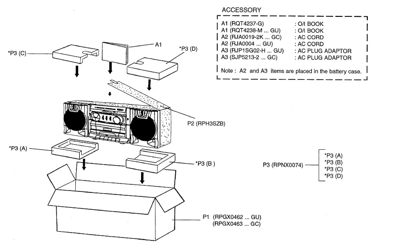
Documents / Resources
 |
Panasonic RX-CS730 Portable Stereo Component System [pdf] Owner's Manual RX-CS730, RX-CS730 Portable Stereo Component System, RX-CS730, Portable Stereo Component System, Stereo Component System, Component System, System |