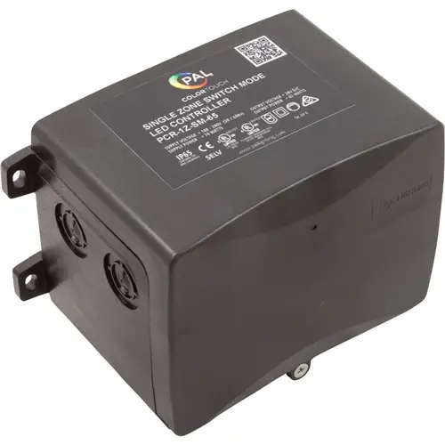
PAL LIGHTING PCR-1Z-SM Multi Color Single Zone Switch Control Transformer
DIMENSIONS

Knockout Instructions
- It is recommended that the cover is fitted and the cover screws tight when the knockouts are being removed.
- When removing the knockouts place a flat blade screwdriver with a 3/16″ (4mm) blade as shown and a light hit with a hammer to the head of the screwdriver will allow the Knockout to be removed.
- Alternatively, drill location points are located in the center of each knockout to allow the use of a hole saw to remove the knockouts.
FEATURES
- Easy to Install
- UL Listed Class 2 Power Supply / Swimming Pool and Spa Transformer (WDGV)
- Remote Control Operation from PCZ-2 hand-held remote
- Optional Wi-Fi Control from Apple iOS Devices
- I P65 Wet Location Construction
- Constant 24V DC Output Voltage over the Supply
IMPORTANT INFORMATION
- This PCR-1 Z-SM/PCR-1 Z/PCR-2Z Class 2 power supply is specifically designed to supply 24V DC to power the PAL 4 Wire UL Listed LED Pool lights.
- The PCR-1 Z-SM/PCR-1 Z/PCR-2Z must be installed in accordance with the National Electrical Code by a Certified Electrician or Qualified Pool Technician.
NOTE: No bonding is required from this Class 2 power supply to the UL Listed PAL Pool Light fixtures as they are made of an all-plastic construction and comply with NEC Article 680 requirements.
INSTALLATION INSTRUCTIONS
FOR PCR-1Z RGB OUTDOOR DRIVER
- Step 1. The PCR-1 Z-SM/PCR-1 Z/PCR-2Z Class 2 Power Supply is a Weatherproof construction (IP65) and should be mounted on a flat surface using the mounting legs on the enclosure with appropriate fixtures for the mounting substrate and in a suitable position to suit the intended location of the PAL 4 Wire LED Pool Lights and installed to comply with all the requirements of the National Electrical Code (NEC) and all relevant local codes and ordinances.
NOTE: The Driver Enclosure must be located a minimum distance of 5 feet measured horizontally from the inside wall of the pool and not less than 1 foot above the maximum pool water level measured to the top of the Driver Enclosure.
NOTE: The enclosure must be mounted using the mounting legs on the enclosure with the screw set supplied. If the enclosure is to be mounted on a concrete or block wall, mark out the mounting hole locations and drill 3/16″ holes using a masonry drill then fit the Star Plugs supplied into the holes and fix using the stainless steel screws supplied?? - Step 2. Using the conduit entry on the bottom (bottom-front on PCR-2Z) right-hand side of the PCR-1 Z-SM/PCR-1 Z/PCR-2Z (as shown) connect the 100-120V power supply to NEC code requirements.
- Step 3. Using the remaining conduit entries at the bottom of the PCR-1 Z-SM/PCR-1 Z/PCR-2Z (as shown}, connect the 4 core wire from the PAL 4 WIRE LED LIGHTS. Please ensure the 4 cores are connected to the correct terminals. 2 x output conduit entries are provided in the enclosure to connect up to 2 x PAL-LED 4 Wire Pool Lights.
- Step 4. The PCR-1 Z/PCR-2Z Driver / Receiver is factory-set to operate with the PCZ-2 Transmitter supplied. Just fit the 2 x batteries supplied with the PCZ-2.
The PCR-1 Z-SM does not operate with the PCZ-2 Transmitter.
Please refer to the information supplied with the PCZ-2 transmitter for full operating instructions and features of the system.
INSTALLATION INSTRUCTIONS FOR PCR-1Z-SM / PCR-1Z RGB OUTDOOR DRIVER

INSTALLATION INSTRUCTIONS FOR PCR-2Z RGB OUTDOOR DRIVER

- Note 1: The PCR-1 Z is suitable for PAL 4 wire lights.
- Note 2: Knock outs are provided in the enclosure to connect up to 2 x PAL 4 wire UL Listed Pool Lights.
- Note 3: An unlimited number of drivers can be controlled by one transmitter.
- Note 4: A maximum number of 4 x Transmitters can be coded to an individual PCR-1 Z
CLONING SETTINGS (PCR-1Z & PCR-2Z AUTOMATION AND PCR-1Z-SM)

Note:
- Must turn off power before making DIP switch selection.
- When synching PAL lights to other OEM lights, static colors will match but color change mode timing may vary.
- If the PAL Lights are to be used with Automation, do not use the hand held remote control and disconnect the WiFi module from the board if so equipped.
- If the Automation does not turn the PAL lights on or off and there is power to the driver, press the Z1 button one time to turn on the PAL Driver.
- Note that the PAL features of infinite color selection and dimmability are not available while in Cloned mode.
ZONE SETTINGS – PCR-2Z ONLY

Other Config Operation
- Must turn off power before making DIP switch selection.
- Dip Switch 2: Toggles between 1 and 2 zone operation
- Dip Switch 1: When in single zone mode, this switch selects whether the driver operates entirely as Z1 or Z2 on the remote.
- Dip Switches 3 & 4 change the approximate color temperature of mixed white lights.

PAL TOUCH PCZ-2 TRANSMITTER HAND HELD REMOTE

FEATURES
- Matching Code – Apply power to the receiver. Then press Z1 once within 5 seconds. The output light will flash white 3 times if matching is successful.
- Clearing Code – Apply power to the receiver. Hold down Z1 for 3 seconds. The output light will flash 6 times if clearing the code is successful.
After successfully clearing the existing code a new code will have to be applied by following the matching code procedure above. - 1 Transmitter (PCZ-2) can operate an unlimited number of Receivers (PCR-1 Z)
- 1 Receiver (PCR-1 Z) can be controlled by a maximum of 4 Transmitters (PCZ-2)
- Touching the color wheel will reset any Mode selection.
- Memory Feature – Remembers color selection after being switched off.
- Once the transmitter and receiver are successfully coded the receiver will remember the code if powered off.
AUTOMATION DEDICATED LIGHT OUTPUT RELAY FOR CLONE MODE

Documents / Resources
 |
PAL LIGHTING PCR-1Z-SM Multi Color Single Zone Switch Control Transformer [pdf] Instruction Manual PCR-1Z-SM, PCR-1Z-SM Multi Color Single Zone Switch Control Transformer, Multi Color Single Zone Switch Control Transformer, Single Zone Switch Control Transformer, Switch Control Transformer, Transformer |