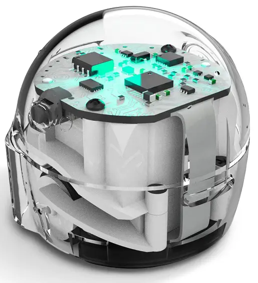
ozobot Bit Plus Programmable Robot
Specifications
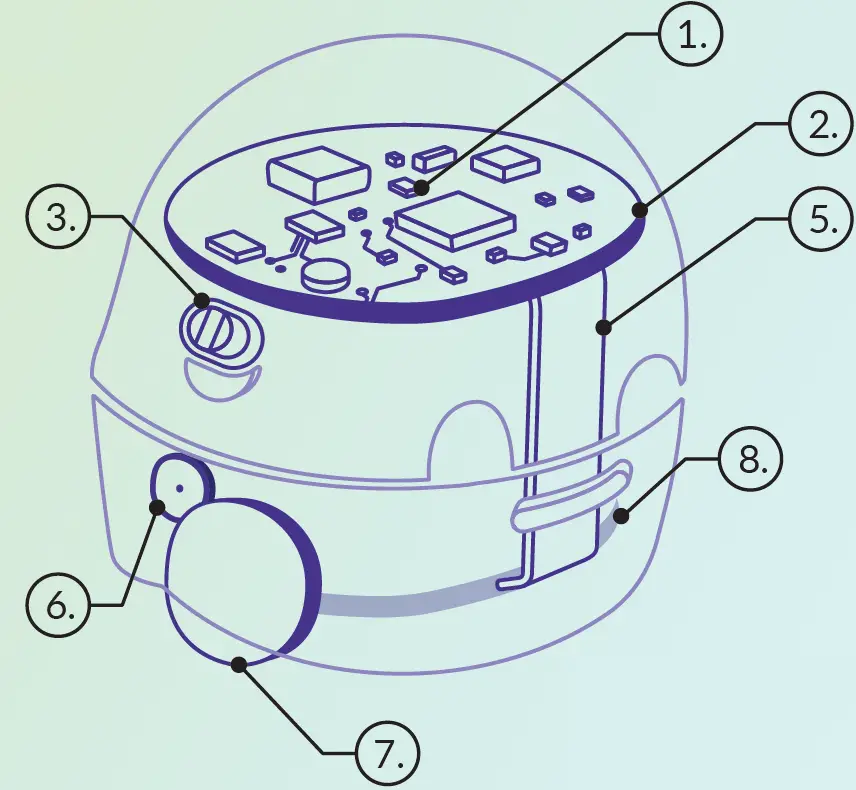
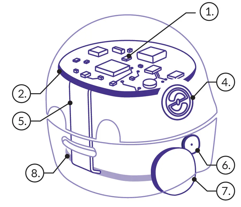
- LED Light
- Circuit Board
- Battery/Program Cut-Off Switch
- Go Button
- Flex Cable
- Motor
- Wheel
- Sensor Board
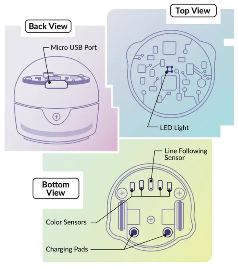
- Micro USB Port
- Color Sensors
- Charging Pads
Product Usage Instructions
Setting up your Ozobot
- Scan the QR code to access the Arduino IDE documentation in English.
- Follow the instructions provided in the packaging for connecting to your computer.
- Select the appropriate port for the product in Tools -> Port -> ***(Ozobot Bit+).
- Upload your program by clicking Sketch -> Upload (Ctrl+U).
Recovering out-of-box functionality
- Navigate to https://www.ozoblockly.com/editor.
- Select Bit+ robot in the left panel.
- Create or load a program from the examples panel.
- Connect Bit+ to the computer via USB cable.
- Click Connect and then Load to restore the stock firmware.
Calibrating your Ozobot
- Draw a black circle slightly bigger than your bot and place Bit+ on it.
- Press and hold the Go Button for 3 seconds until the top LED flashes white, then release.
- Bit+ will move outside the circle and blink green when calibrated. Restart if it blinks red.
When to Calibrate
- Calibration is important when changing surfaces or screen types to improve accuracy in code and line reading. For more tips, visit ozobot.com/support/calibration.
Introduction to Ozobot
Left View
 Right View
- LED Light
- Circuit Board
- Battery/Program
Cut-Off Switch - Go Button
- Flex Cable
- Motor
- Wheel
- Sensor Board
Scan the QR code to access the Arduino IDE documentation in English. Follow the instructions there without performing a calibration – calibration is not the first step.
Quick Start Guide
Download and install the latest version of Arduino® IDE.
- Download and install the latest version of Arduino® IDE. Arduino IDE version 2.0 and later is supported.
- Please note: the steps will not work with Arduino® version older than 2.0.
- Note: If the Arduino software download link doesn’t work, you can search using Google or another search engine. Just type “Arduino IDE download” and you will find the latest version available for your device.
In the Arduino® IDE software
- File -> Preferences -> Additional Board Manager URLs:
- Copy and paste the following
URL: https://static.ozobot.com/arduino/package_ozobot_index.json
- Copy and paste the following
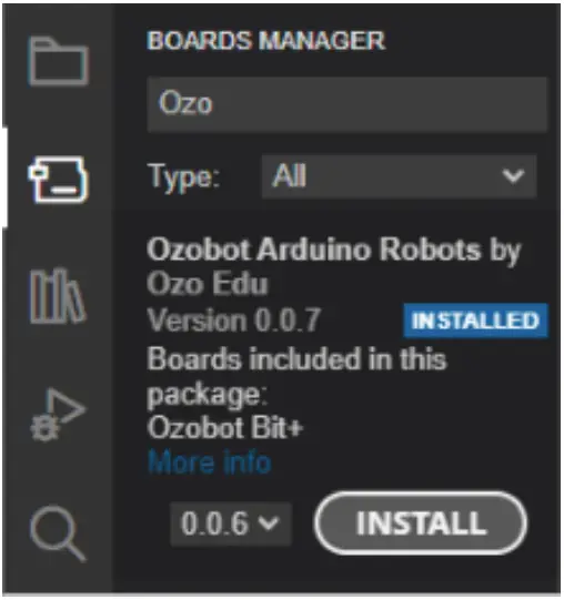
- Tools -> Board -> Boards Manager
- Search for “Ozobot”
- Install the “Ozobot Arduino® Robots” package
Compile and load an example program to Ozobot Bit+
- Tools -> Board -> Ozobot Arduino® robots
- Select “Ozobot Bit+”
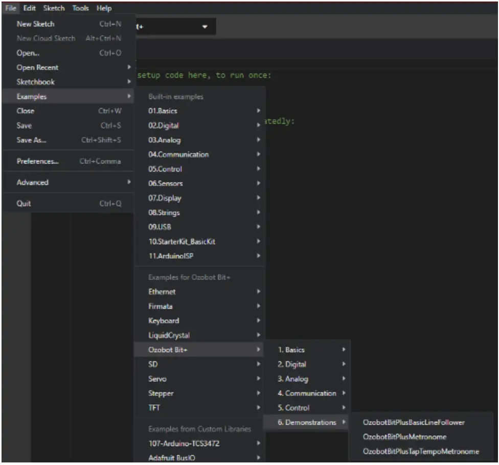
- File -> Examples -> Ozobot Bit+ -> 1. Basics -> OzobotBitPlusBlink
- Connect the product to the USB port of the computer using the USB cable provided in the packaging
- Tools -> Port -> ***(Ozobot Bit+)
- (Select the appropriate port of the product. If unsure, test all available sequentially until one is successful.)
- Sketch -> Upload (Ctrl+U)
- Ozobot will flash all of its LED outputs in half-second intervals. The Bit+ is not able to do any other operation until a different Sketch or default firmware is uploaded.
Installation
Installing 3rd Party Arduino® Boards to Arduino® IDE
The versatility and power of Arduino® comes from the fact that it is open source. Due to the nature of open source ecosystems you’re able to design your own Arduino”-based boards and make code libraries to go along with them. Some developers even include an example library of Arduino® sketches to help you learn their functions, constants, and kevwords.
- First, you need to locate the board package link. The link will point to this will come in the form of a json file. For Ozobot Bit+ Arduino® package, the link is https://static.ozobot.com/arduino/package_ozobot_index.json. Open up Arduino IDE and hit ‘Ctrl +, (control and comma) if you’re on PC and Linux. If you’re using a Mac, it will be ‘Command + ,.
- You’ll be greeted with a version of this screen:
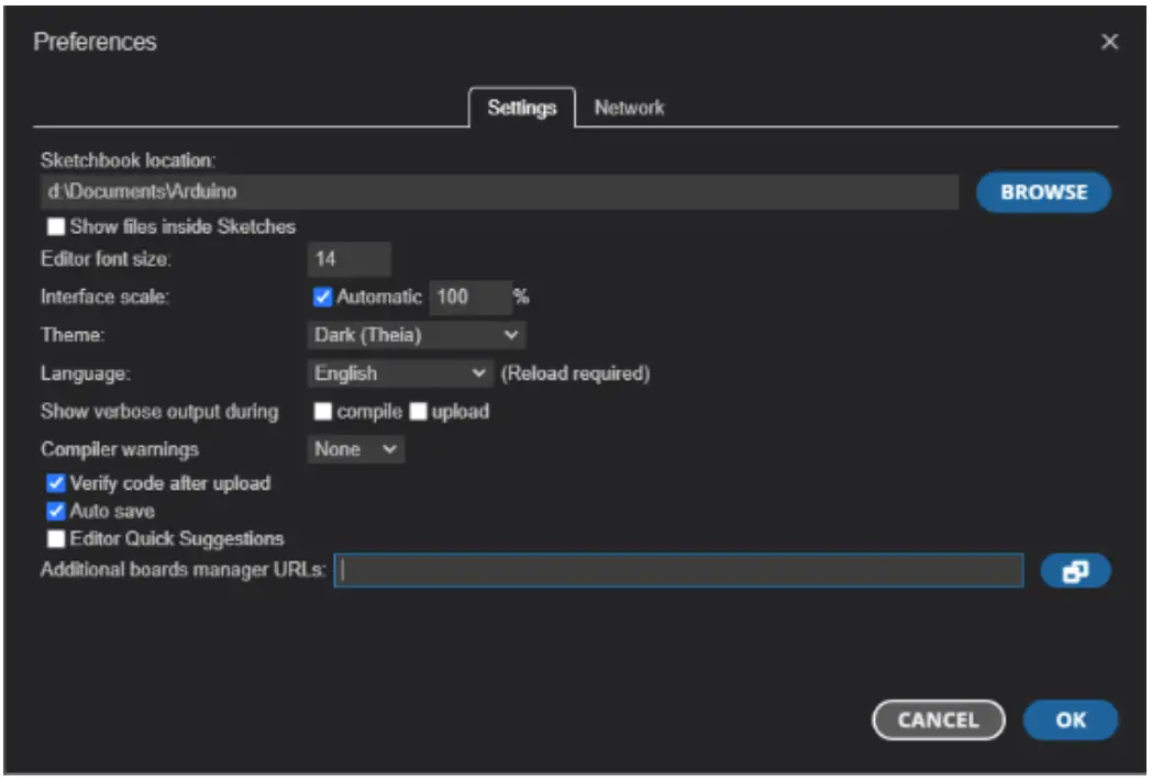
- At the bottom of the window, you’ll see an option to add ‘Additional board manager URLs’, You can post the json link there or click the icon with two small boxes to add multiple boards to your board manager at once. You just have to hit enter/return after you put a link into the box to start a new line.
- You can add the Ozobot Bit+ plus board with this link: https://static.ozobot.com/arduino/package_ozobot index.json
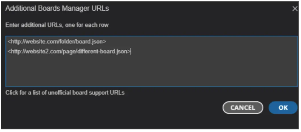
- Once you’ve posted your links in the box hit ok and exit the preferences menu.
- You can now click on the second option on the side bar, it’s a little circuit board which will open the board manager menu. You can now click “Install” to get all the necessary files to program with your board, in this case the Ozobot Bit+.
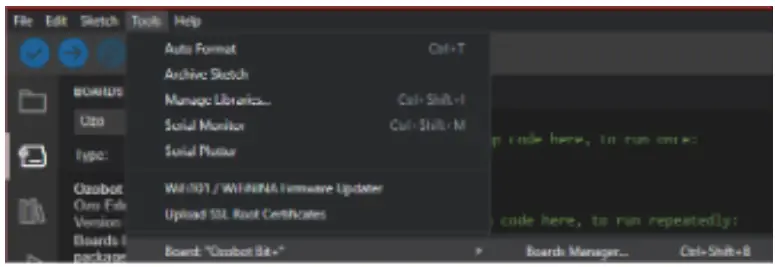
- You can also click on “Tools” on the menu bar at the top and find the Board Manager in the “Board:” sub-menu. Or by hitting ‘CtrI+Shift+B’ on Windows and Linux (‘Command+Shift+B’ on Mac).
- After you’ve installed the files for your Arduino® board, restart your software to make sure that Arduino® is aware of all the files you just installed.
- Next you’ll want to click the drop down at the top of your window and select the board you want and which port it’s plugged into on your computer:
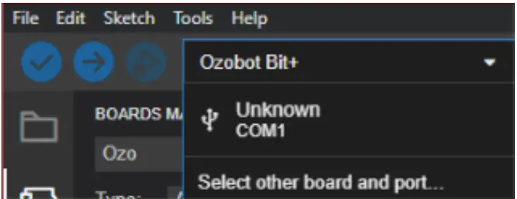
- In this case we chose Ozobot Bit+ on COM4 virtual serial port. If your board doesn’t appear in this list click on the “Select other board and port option”:
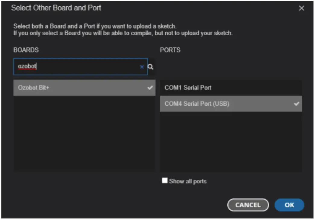
- You can search for your board by typing in the top left box, as you can see we’ve searched for’ozobot’ and selected the Ozobot Bit+ Board connected to COM4, click OK.
- To look at the included example sketches available for your new board click on “File” then hover over “examples” and you’ll see a menu populated with the standard Arduino® examples, followed by all the examples from libraries that your Board is compatible with. As you can see, we’ve included some modified versions of some of the standard Arduino® examples as well as added some custom ones, in the “6. Demonstration” sub-menu.
Just as easy as that, you’ve installed the supporting files for your board and are ready to start exploring a new environment in the world of Arduino.
Recovering the “out-of-box” Bit+ functionality Loading an Arduino® sketch to the Bit+ robot will overwrite the “stock” firmware. That means the robot will execute the Arduino® firmware and is not capable of the usual “Ozobot” functionality, such as following lines and detecting color codes. The original behavior can be recovered by loading the “stock” firmware back to the Bit+ unit that was previously programmed with Arduino IDE. To load the stock firmware, use Ozobot Blockly:
- Navigate to https://www.ozoblockly.com/editor
- Make sure to select “Bit+” robot in the left panel
- Create any program, or load any program from the “examples” panel on the right.
- On the right side, click the “Programs” icon, so the right panel opens
- Make sure Bit+ is connected to the computer via USB cable
- Click the “Connect” button
- Click the “Load” button.
- The Bit+ stock firmware will be loaded to the robot, together with the Blockly program (not important, as we did this exercise to load the stock FW in first place)
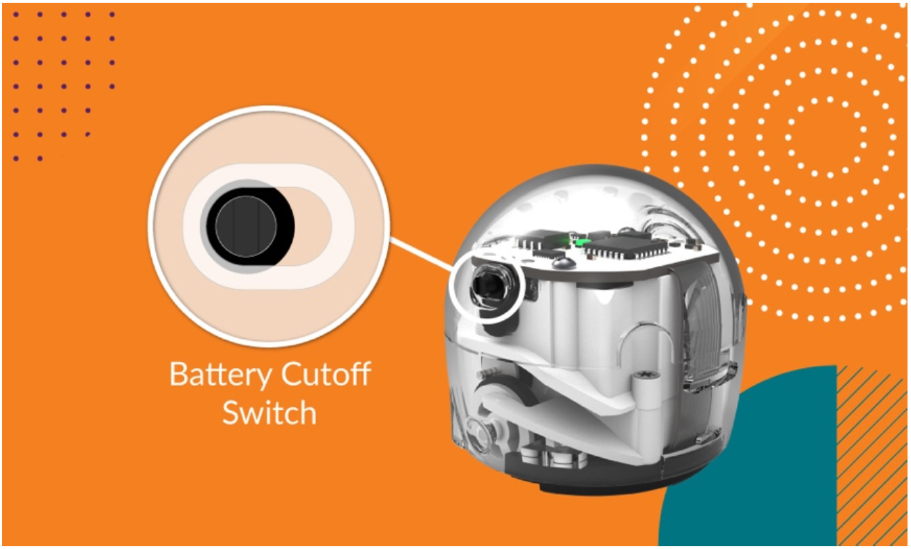
Battery Cutoff Switch
There is a slide switch on the side of the robot that will turn the robot off. This is especially handy if you loaded an Arduino® program that does some repetitive action, but cannot suspend itself. The slide switch will always stop the program as it disconnects the battery. However, when connected to a charger, the battery will always start to charge and the Arduino® sketch will run, no matter the position of the slide switch.
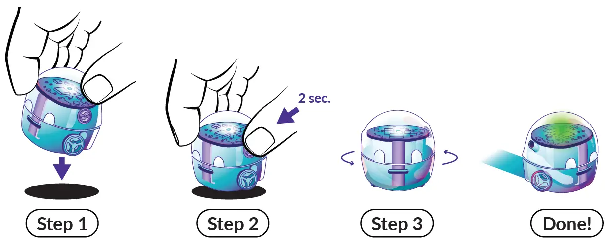
How Do I Calibrate?
Step 1
- Draw a black circle, slightly bigger than your bot. Fill with Black Marker Place Bit+ on it.
Step 2
- Press and hold the Bit+ Go Button for 3 seconds (or until its top LED flashes white), then release.
Step 3
- Bit+ will move outside the circle, and blink green when calibrated. If Bit+ blinks red, start over from Step 1.
When to Calibrate?
- Calibration helps improve Bit+ code and line reading accuracy. It is important to calibrate when you change surfaces or screen types.
When in doubt, calibrate!
- For tips on how and when to calibrate, please go to ozobot.com/support/calibration
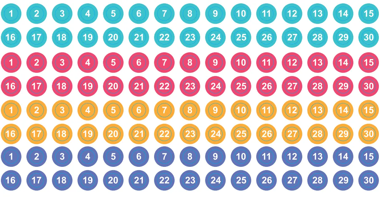
Bot Labels
Find bot classroom management tips at support@ozobot.com
FAQ
- Q: How do I calibrate my Ozobot?
- A: To calibrate your Ozobot, follow these steps:
- Step 1: Draw a black circle slightly bigger than your bot and place Bit+ on it.
- Step 2: Press and hold the Go Button for 3 seconds until the top LED flashes white, then release.
- Step 3: Bit+ will move outside the circle and blink green when calibrated. Restart if it blinks red.
- A: To calibrate your Ozobot, follow these steps:
- Q: Why is calibration important?
- A: Calibration helps improve code and line reading accuracy, especially when changing surfaces or screen types. It is recommended to calibrate whenever unsure.
Documents / Resources
 |
ozobot Bit Plus Programmable Robot [pdf] User Guide Bit Plus Programmable Robot, Bit Plus, Programmable Robot, Robot |