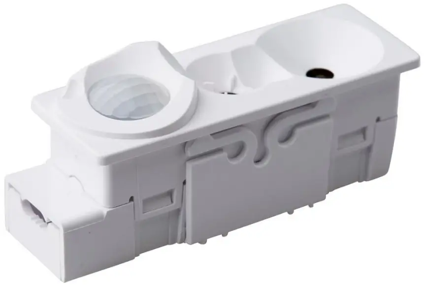
Organic Response Sensor Node 3 Wireless Plug and Play Lighting Control System
TECHNICAL DATASHEET
Sensor Node 3 VX.Y, 07/03/2024 Sensor Node 3 (SN3), the third-generation sensor node in the Organic Response range, delivers reduced size and cost while featuring advanced occupancy and daylight sensing. SN3 is the first Organic Response node designed with connectivity at its core. SN3 communicates with – and is powered by – the luminaire driver over a 2-wire DALI interface1, reducing component count, wiring complexity, and integration cost. For communication external to the luminaire, the SN3 employs a dual-layer communication architecture. Organic Response proprietary IR messaging is used for proven real-time control between neighboring nodes, while an industrial grade low energy RF mesh network is used for communication via a gateway to Building Management Systems (BMS) and/or the Cloud.
OVERVIEW
Sensor Nodes and their communications form the foundation of Distributed Intelligence which lies at the heart of the Organic Response System. Each Sensor Node has a motion detector, ambient light sensor, infrared transceiver, and an RF transceiver. Ideally (and typically) Sensor Nodes are integrated into each luminaire at the point of manufacture. Sensor Nodes control the light output of their associated luminaire using a DALI two-wire connection to the luminaire Driver. Light output is based on a combination of information the Sensor Node collects from its environment, and information it receives from neighboring Sensor Nodes, Wall Switches, smartphones, or other devices connected via the OR IoT Gateway. Sensor Nodes have numerous configurable parameters, including, but not limited to:
- Max Light Level
- Personality
- Dwell Time
- Daylight Dimming
- Scenes
- Zones
Further information on the configuration and use of these parameters can be found in the User Guide 2.0 at the Organic Response website www.organicresponse.com.
MOTION SENSOR
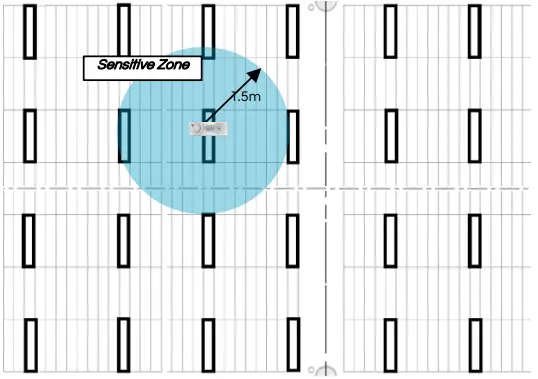
Figure 2 – Detection Range of a single Sensor Node imposed over a Typical RCP (1.5m circular radius, 2.7m luminaire height)
KEEPING THE OIC CONTIGUOUS
Organic Response Sensor Nodes communicate with each other wirelessly to form a smart sensor network which we call the Occupancy Information Cloud (OIC) TM. The system relies on peer-to-peer communication between neighboring Sensor Nodes to maintain the integrity of the OIC and allow the light fittings to operate as a system. For this reason, nodes must be installed with the spacing indicated below:
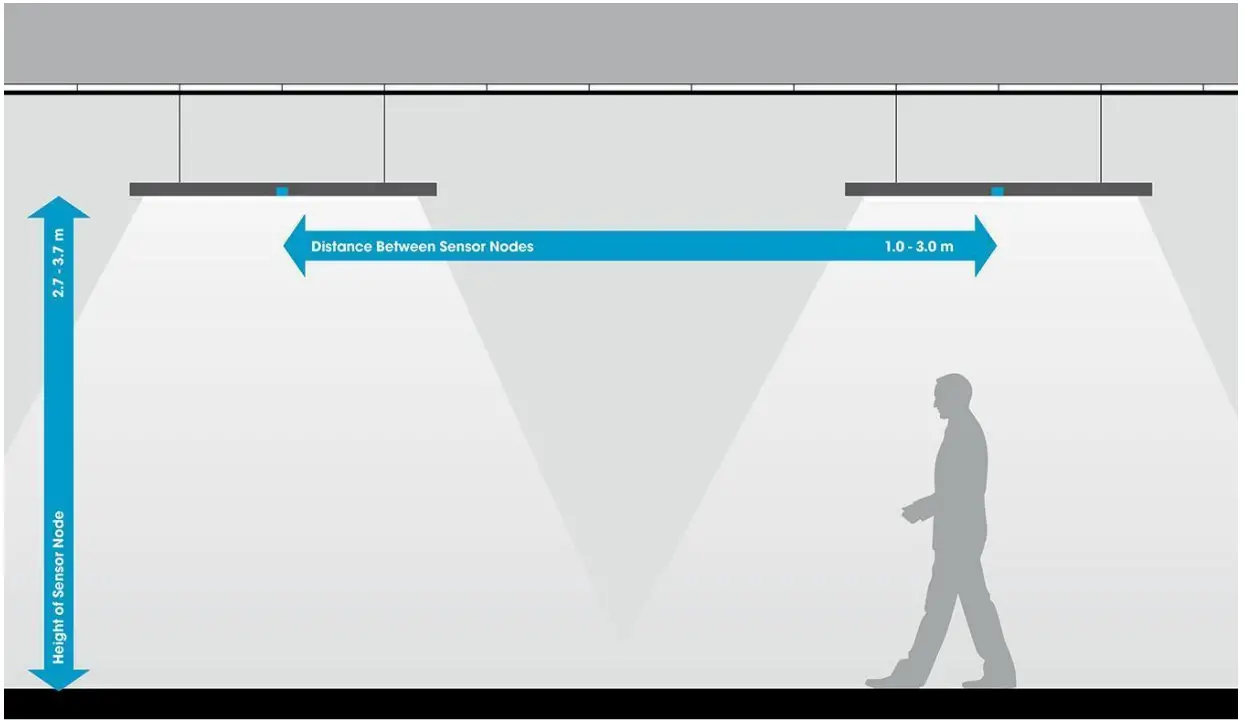
Figure 3: Recommended mounting height and neighbor spacing.
|
TECHNICAL DATA |
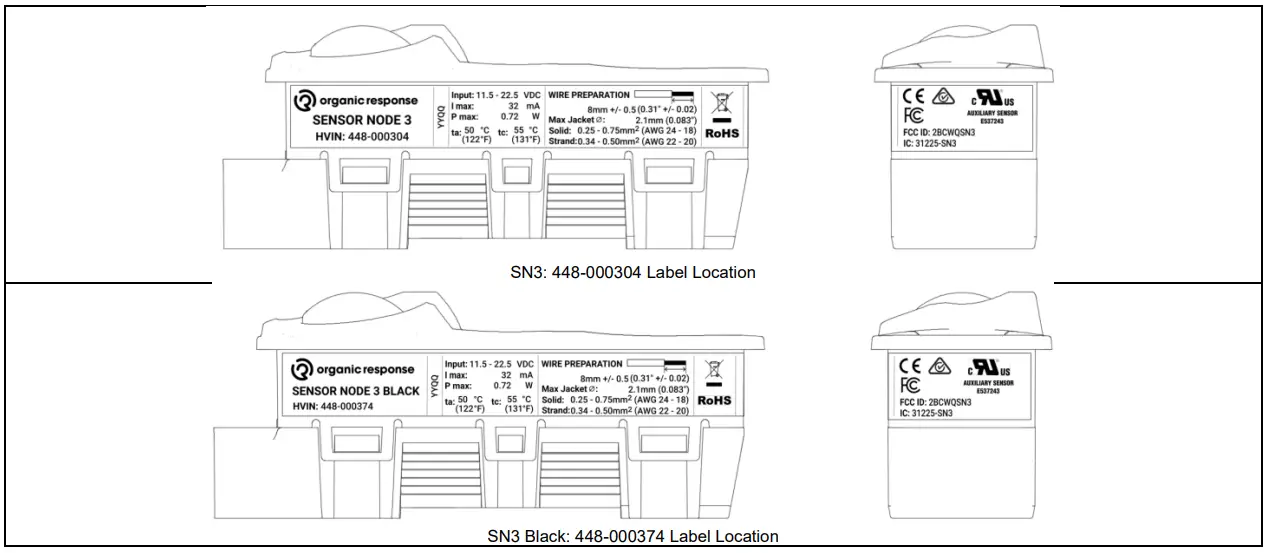
PART #: 448-000304 SENSOR NODE 3 WHITE PART #: 448-000374 SENSOR NODE 3 BLACK |
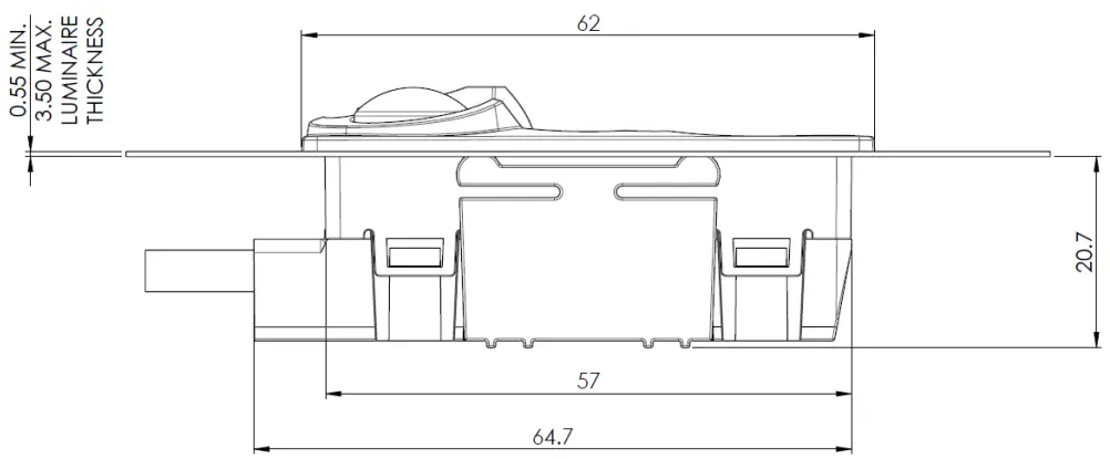
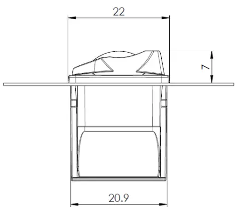
| DIMENSIONS | H: 28.35mm x L: 62mm x W: 22mm |
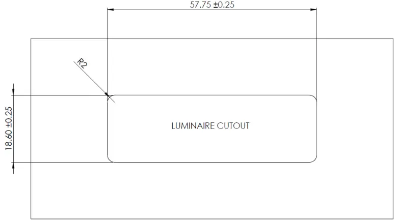
| CUT-OUT DIMENSIONS | L: 57.75mm +/- 0.25mm x W: 18.6mm +/- 0.25mm |
| PLATE THICKNESS | Min: 0.55mm Max: 3.50mm |
| WEIGHT | 25g |
| POWER SUPPLY | 11.5 – 22.5V, must be current limited to <250mA |
| CURRENT CONSUMPTION | Nominal: 18mA Maximum: 32mA |
| NUMBER OF DALI DEVICES SUPPORTED | DALI PSU dependent up to a maximum number of 12 devices |
| COMPATIBLE POWERED DALI DRIVERS | Philips SR, OSRAM Dexal, and Tridonic drivers with integrated DALI bus power supply |
| DIMMING | Logarithmic
Note: The DALI driver must be configured for the logarithmic dimming function. |
| SENSOR NODE AMBIENT TEMPERATURE (a) | 0ºC … 50ºC |
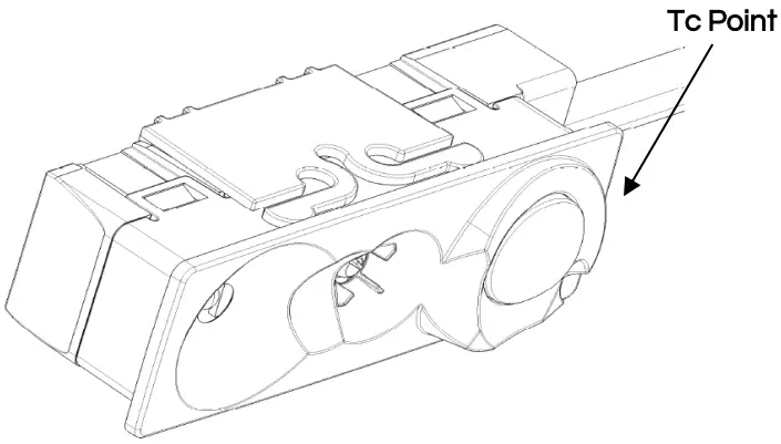
| SENSOR NODE CASE TEMPERATURE
(tc) |
0ºC … 55ºC |
| NODE TO NODE COMMUNICATION PROTOCOL – CONTROL | Organic Response – Wireless infrared |
| NODE TO NODE COMMUNICATION PROTOCOL – DATA | Wirepas – Wireless RF |
| RF FREQUENCY BAND | 2.4 GHz |
| RF RANGE – NODE TO NODE | 8m – non-LOS (max) |
|
J1 and J2 TERMINALS |
Wire Type: 0.25 – 0.75mm2 (solid)
0.34 – 0.50mm2 (stranded) Strip Length: 8mm +/- 0.5mm |
|
RF OPERATIONAL PERFORMANCE |
Ability to operate in an office environment with performance unaffected by surrounding structures, walls, ceilings, enclosures, and other RF devices that may be present. |
| NODES PER IoT GATEWAY | 150 (max) – this limit is based on bandwidth and redundancy for general cases. Please contact OR Technologies for further information about this limit for custom application |
| PRODUCT ENVIRONMENT FOR USE | Indoor areas, with a maximum recommended ceiling height of 3.7m |
|
EMC COMPLIANCE |
EN 55015: 2015
EN 61547: 2009 ETSI EN 301 489-1 V2.1.1 (2017-02) ETSI EN 301 489-17 V2.2.1 (2012-09) ETSI EN 301 489-1 V3.1.1 (2017-02) |
| RADIO COMPLIANCE | ETSI EN 300 328 V2.1.1 (2016 – 11) |
|
ELECTRICAL SAFETY COMPLIANCE |
AS/NZS 61347.2.11 :2003
AS/NZS 61347.1:2016 IEC/EN 61347-12-11:2001 IEC/EN 61347-1:2015 IEC 60695-10-2-2004 (Ball pressure test on Sensor Node 3 Black) AS/NZS 60695.10.2:2004 (Ball pressure test on Sensor Node 3 Black) IEC 60695-2-10:2001 (Glow wire test on Sensor Node 3 Black) |
|
COMPLIES WITH EC DIRECTIVES |
EMC Directive 2014/30/EU
Radio Equipment Directive 2014/53/EU RoHS2 Directive 2011/65/EU |
| ATS COMPLIANCE FOR BATTERY-POWERED EMERGENCY LIGHTING | EN 62034:2012
Note: All SN3-enabled Emergency Lighting Units must have a “Type PER” mark on the luminaire panel and must be visible at the time of installation to adhere to EN 62034 |
|
FCC CERTIFICATION |
FCC ID:2BCWQSN3 This device complies with Part 15 of the FCC Rules. Operation is subject to the following two conditions: (1) this device may not cause harmful interference, and (2) this device must accept any interference received, including interference that may cause undesired operation. |
| ISED CERTIFICATION | IC: 31225-SN3 |
|
UL RECOGNITION |
This device is evaluated for use in Pollution Degree 2 environments. This device is evaluated as a Type 1, Operating Control (non-safety) with a Class A control function. |
DIMENSIONS, LUMINAIRE CUT-OUT MATERIAL THICKNESS:
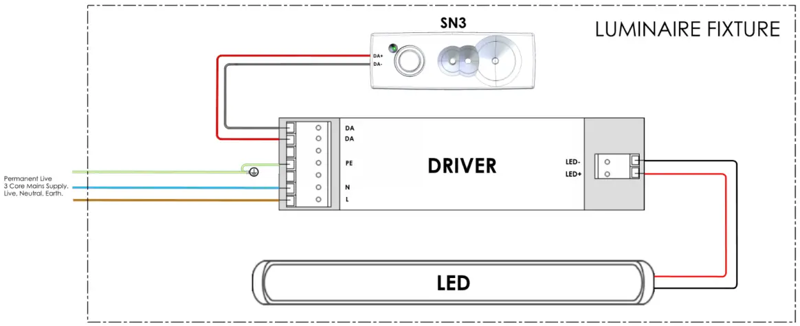
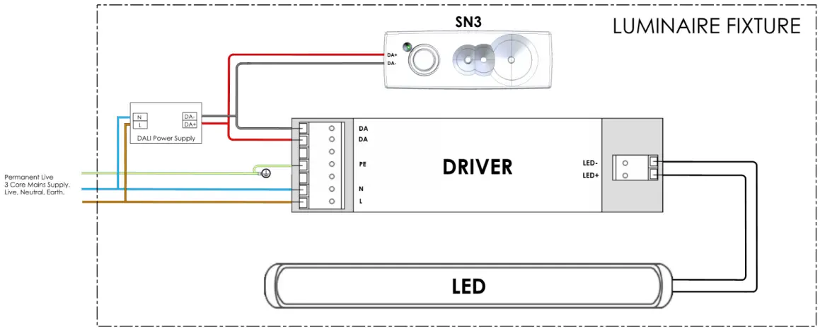
WIRING DIAGRAMS:
- DALI drivers with integrated DALI Bus power supply
- Standard DALI Drivers
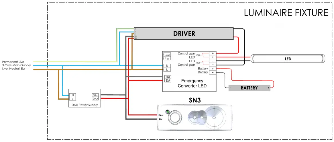
EMERGENCY WIRING DIAGRAMS – DEFAULT CONFIGURATION:
- DALI drivers with integrated DALI Bus power supply

- Standard DALI Drivers
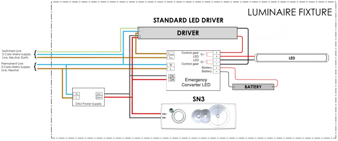
EMERGENCY WIRING DIAGRAMS – ALTERNATE CONFIGURATION:
Note: The following configurations require full testing to verify correct performance.
- DALI drivers with integrated DALI Bus power supply
Note: This configuration is fully applicable to Philips TrustSight Emergency Controllers Gen3 (and later versions) and on both TrustSight DALI and IDT (Instant Duration Test) versions in combination with Philips SR LED drivers.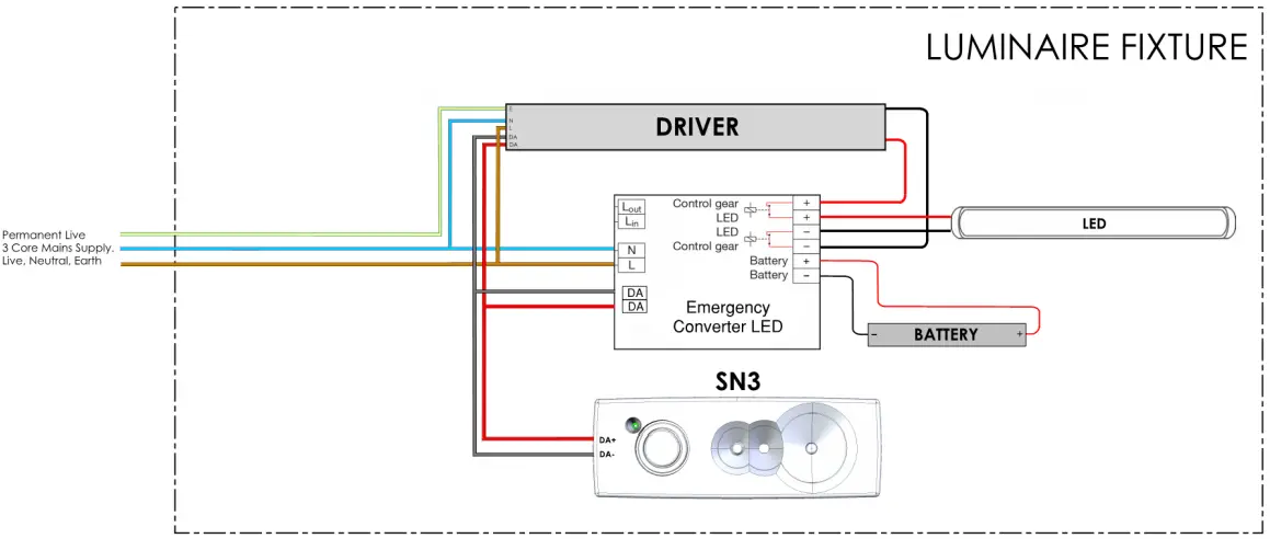
- Standard DALI Drivers
TC POINT TEMPERATURE:
Subject to change without notice. Please contact OR Technologies for further details.
COMPLIANCE INFORMATION
FCC: FCC ID:2BCWQSN3
This device complies with Part 15 of the FCC Rules. Operation is subject to the following two conditions:
- This device may not cause harmful interference, and (2) this device must accept any interference received, including interference that may cause undesired operation.
Caution: The user is cautioned that changes or modifications not expressly approved by the party responsible for compliance could void the user’s authority to operate the equipment.
Note: This equipment has been tested and found to comply with the limits for a Class B digital device, under part 15 of the FCC Rules. These limits are designed to provide reasonable protection against harmful interference in a residential installation. This equipment generates, uses, and can radiate radio frequency energy and, if not installed and used by the instructions, may cause harmful interference to radio communications. However, there is no guarantee that interference will not occur in a particular installation. If this equipment does cause harmful interference to radio or television reception, which can be determined by turning the equipment off and on, the user is encouraged to try to correct the interference by one or more of the following measures:
- Reorient or relocate the receiving antenna.
- Increase the separation between the equipment and the receiver.
- Connect the equipment to an outlet on a circuit different from that to which the receiver is connected.
- Consult the dealer or an experienced radio/TV technician for help.
This equipment complies with FCC’s RF radiation exposure limits set forth for an uncontrolled environment. The antenna(s) used for this transmitter must be installed and operated to provide a separation distance of at least 20 cm from all persons and must not be collocated or operating in conjunction with any other antenna or transmitter. Installers must ensure that a 20cm separation distance will be maintained between the device (excluding its handset) and users.
ISED: IC: 31225-SN3
This device contains license-exempt transmitter(s)/receiver(s) that comply with Innovation, Science, and Economic Development Canada’s license-exempt RSS(s). Operation is subject to the following two conditions:
- This device may not cause interference.
- This device must accept any interference, including interference that may cause undesired operation of the device.
L’émetteur/récepteur exempt de licence contenu dans le présent appareil est conforme aux CNR d’Innovation, Sciences et Développement économique Canada applicables aux appareils radio exempts de licence. L’exploitation est autorisée aux deux conditions suivantes :
- 1.L’appareil ne doit pas produire de brouillage ;
- 2.L’appareil doit accepter tout brouillage radioélectrique subi, même si le brouillage est susceptible d’en compromettre le fonctionnement.
- This Class [B] digital apparatus complies with Canadian ICES-003.
- Cet appareil numérique de la classe [B] est conforme à la norme NMB-003 du Canada.
- This equipment complies with Canadian radiation exposure limits set forth for uncontrolled environments. This equipment should be installed and operated with a minimum distance of 20cm between the radiator and your body.
- This transmitter must not be co-located or operating in conjunction with any other antenna or transmitter.
Déclaration d’IC sur l’exposition aux radiations:
- Cet équipement est conforme aux limites d’exposition aux radiations définies par le Canada pour des environnements non contrôlés. Cet équipement doit être installé et utilisé à une distance minimum de 20 cm entre l’antenne et votre corps.
- Cet émetteur ne doit pas être installé au même endroit ni utilisé avec une autre antenne ou un autre émetteur.
Documents / Resources
 |
organic response Sensor Node 3 Wireless Plug and Play Lighting Control System [pdf] Owner's Manual SN3, Sensor Node 3 Wireless Plug and Play Lighting Control System, Sensor Node 3, Wireless Plug and Play Lighting Control System, Plug and Play Lighting Control System, Play Lighting Control System, Lighting Control System, Control System, System |


