![]() BCB-4 User’s Manual
BCB-4 User’s Manual
Automatic Bias Controller
BCB-4 Automatic Bias Controller
Caution: The user must read this manual before operating the BCB-4 unit.
Operations other than those described in this manual may result in personal injury and/or damage to the unit.
Note that any attempt to open or fix the equipment without prior approval by Optilab, LLC voids the warranty.
Ver. 2.0
July 15th , 2024
Revision History
| VERSION | DATE | SUMMARY |
| 0.1 | 06/12/2020 | Manual introduced. |
| 1.0 | 08/13/2020 | Manual Released. |
| 1.1 | 09/01/2020 | Added manual bias mode. |
| 1.2 | 10/15/2020 | Added Vpi measurement function. |
| 1.3 | 03/15/2021 | Specification Modified |
| 1.4 | 04/26/2022 | Added information for setting Vpi or using a feedback loop. |
| 1.5 | 08/18/2022 | Modified command set |
| 2.0 | 07/15/2024 | Updated command set per firmware Ver. 1.3.3 |
Copyright © 2024 by Optilab, LLC
All rights reserved.
This document is copyrighted property of Optilab, LLC. It may not be used in whole or in part for manufacture, sale, or design of items without the written permission of Optilab, LLC.
Information herein is preliminary and subject to change without any notices.
General Information
1.1 Introduction
This manual contains information on the installation and operation of the BCB-4 bias controller board module unit.
1.2 Product Overview
The Optilab BCB-4 is a compact bias control board designed to maintain the bias operating point of an MZI based optical intensity modulator. Featuring a miniature design for OEM integration, the BCB-4 allows for a stable Q+, Q-, Min, and Max operation over long periods of time. In addition to the automatic bias modes, BCB-4 also supports the manual bias mode. Featuring a single +5V DC power and RS-485 multi-addressing control and monitor interface, the BCB-4 unit is the ideal choice for industrial and OEM applications when paired with any of Optilab’s wide variety of optical modulators, contact Optilab for more information.
1.3 Features
- Q+, Q-, Min, Max, and manual bias setting modes
- Single +5V DC power
- Compatible with all MZI optical modulators
- On-board photodiode for external optical tap (optional)
- RS-485 interface for control and monitoring
1.4 User Safety
- The BCB-4 unit operates with optical modulator products that utilize visible or invisible laser sources. Avoid direct exposure to skin and eyes.
- The user should never modify the PCB component; any attempt will void the warranty and may result in electric shock and EMS attack to equipment in the vicinity.
- The user should avoid using any solvent or vaporizing chemical to clean the components; it may result in damage to the surface and circuits.
Operation
2.1 Introduction
This chapter describes how to operate the BCB-4 unit and discusses the location and function of the controls and connectors.
2.2 Initial Inspection
Your BCB-4 unit was carefully inspected before it left the manufacturer. It should be in proper working order upon receipt. You should, however, inspect the unit for any damage that may have occurred in transit. If the shipping container or the packing material is damaged, keep it until the contents of the shipment have been checked to be free of mechanical and electrical damages.
Notify Optilab, LLC promptly if any notable damage is found.
Each BCB-4 shipment should include the following:
- BCB-4 module unit
- User Manual
- Test Data, including Calibration Data if ordered with PD
- PA-D, POWER/COM interface module
- 6-pin POWER/COM interconnect cable
- 2-pin bias interconnect cable
- 4-pin Molex power interconnect cable
- USB Cable
Optional accessories:
- Optilab PS-5-M, ±5V DC power supply
2.3 Controls

| FEATURE | FUNCTION |
| 1 POWER/COM CABLE CONNECT PORT | This port supplies +5V DC power and allows the user remote control access via RS-485, please see section 2.5 of this manual for more information. Socket Model: JST S6B-ZR; Mating Connector: JST ZHR-6 |
| 2. PROGRAMMING HEADER | Manufacturer use only. PIN#3 is the GND pin for probing. |
| 3. RESET BUTTON | This button is utilized to reset the internal automatic bias locking algorithm; if the bias feature is not locking properly, or the input condition has changed, press this button to reset the bias operation. |
| 4. ONBOARD PHOTODETECTOR (OPTIONAL) | This photodiode works in conjunction with a tap coupler to provide feedback of the output signal of the modulator. |
| 5. DITHER SIGNAL ADJUST | This potentiometer adjustments the 1 kHz dither signal from approximately 0 to 450 mVp-p. |
| 6. BIAS OUTPUT PORT | This two-pin port is used to relay the corresponding DC bias out to the modulator. Details on the pin-out are noted in section 2.5 of this manual. Socket Model: JST B2B-ZR; Mating Connector: JST ZHR-2 |
POWER/COM Interface Module
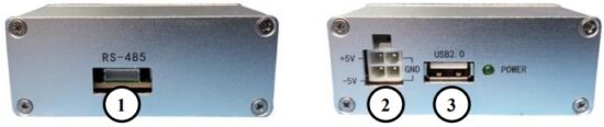
| FEATURE | FUNCTION |
| 1. RS-485 CONNECTION PORT | Connection of this port to the BCB-4 provides power to the unit and remote control of the device via RS-485 protocol. |
| 2. DC POWER PORT | Connect this port to the Optilab PS-5 power supply (with the provided 4- pin Molex cable), or to the appropriate +5VDC, -5VDC, GND terminals. The pin out diagram is noted in Appendix A at the end of this manual. The Power LED will enable when the proper connection and supply is made. Please note that -5V DC power is not used by BCB-4 and does not need to be connected. Connecting -5V DC power supply does not damage anything. |
| 3. USB PORT | This port connects to any standard PC interface to allow for the remote access and feature adjustment options. |
2.4 Connection Diagram
The following block diagram denotes the typical connection of the BCB-4 to increase the understanding to the end user on its operation and interconnectivity. The BCB-4 bias controller utilizes an on-board photodetector power monitor. In this monitor / feedback fashion, the automatic bias control circuit (BCB-4) is used to ensure the modulator bias point is maintained at the desired level.
2.5 Operation Instructions
Start-up Procedure
To assist with connections, please see the pin out diagram below for the BCB-4:
- Ensure that the DC bias and ground ports are securely always connected to the intensity modulator.
- Use an optical tap coupler on the output port of the intensity modulator to provide optical feedback to the PD of the BCB-4. Without this connection the BCB-4 will not function properly. The split ratio of the tap coupler should be selected based on the optical input power to the intensity modulator and the modulator’s insertion loss and should be between -20 and -10 dBm when the modulator is biased to maximum point.
NOTE: An optical feedback loop is required for automatic bias operation of the BCB-4 device. This feedback loop will allow the device to measure the Vpi of the connected modulator and allow for proper biasing. Alternatively, the Vpi value can be set manually to BCB-4, please refer to the Remote-Control section of this manual for setting this value. - Make all necessary electrical connections including:
• BCB-4 bias port to modulator bias pins using the provided 2-pin cable.
• BCB-4 power/COM port to interface module RS-485 port using the provided 6-pin cable.
• Interface module Molex connection to power supply using the provided 4-pin Molex cable.
• Interface module USB port to PC USB port using the provided USB cable. - Enable seed laser input to the modulator.
- To change the bias control point between Q+, Q-, Min, Max, or manual mode, please refer to the Remote-Control Procedure located in the latter portion of this section.
- The BCB-4 unit is now fully operational; however, it may take 60 to 90 seconds for the bias controller to initialize and accurately adjust to the desired bias point setting.
Dither Amplitude Adjustment Procedure
Utilizing the potentiometer marked in the diagram in section 2.3 of this manual, rotate this adjustment knob to increase or decrease the dither amplitude value, from approximately 20 to 450 mVpp. This dither signal can be measured at the test point on the PCB marked ‘Dither’. The dither frequency of 1 kHz is fixed and cannot be adjusted. The dither amplitude should be approximately 2% to 5% of the intensity modulators bias port Vpi. For MIN mode operation, a smaller dither signal ~1% or lower is required to achieve high extinction ratio.
Remote Control Procedure
- To offer full remote control and to set the internal BCB-4 bias setting mode, you will need to set up an appropriate PC, with an appropriate serial port communication protocol software installed. You will also need to ensure that the appropriate RS485 drivers are installed to match your operating system of choice.
- Once the drivers have been installed, connect the BCB-4 to a USB port on the desired computer. The BCB-4 device should be recognized as a COM port device under the Device Manager. If it is not recognized, then you will need to locate the appropriate driver first in step one and repeat.
- Once the BCB-4 is recognized by the PC interface, you are now ready to send the remote commands to the BCB-4. The device uses the following serial port communication protocols, ensure that your serial port communication program is set appropriately:
| Baud Rate: | 9600 bps |
| Data Bits: | 8 |
| Stop Bits: | 1 |
| Parity: | None |
| Flow Control: | None |
| Text Transmission: | Append CR, LF |
2.6 RS485 Command Set
When the electrical connections have been made, and the software settings for serial port transmission are set correctly, you are now able to send commands to the BCB-4 module.
Please refer to Appendix B at the end of this manual for command set and the layout of the return from the READ command.
2.7 Bias Control Point Setting Information
For setting the bias control point of the BCB-4 controller, the choices are MAX, MIN, Q+, and Q-, please refer to the diagram below. For pulsed applications, use the MIN point, for maximum output power, use the MAX point, and for typical RF over fiber applications, use Q+ or Q- to minimize the 2nd and 3rd order distortion harmonics.
Troubleshooting
| SYMPTOM | POSSIBLE CAUSE AND SOLUTION |
| UNIT NOT BIASING CORRECTLY | C: Improper bias pin connection setting. S: Check to ensure that the cable between the BCB-4 and the intended optical modulator is made correctly. |
| C: Optical input to the modulator is too high/low. S: Due to the photodiode feedback design, the ability to bias the modulator depends on the amount of photodiode current feedback to the BCB-4. If the feedback power is greater than -10 dBm, it may saturate the BCB-4 photodiode current measurement. If it is lower than -20 dBm, then the feedback strength may be insufficient. |
|
| C: Onboard photodiode input is too high/low. S: Ensure that the optical input level through the tap port is between -20 dBm and -10 dBm for optimum performance. |
|
| C: Improper polarization input to modulator. S: Check the input polarization type and axis alignment of your modulator and confirm the input seed source is matching. An improper optical input axis alignment will render the BCB biasing (especially minimum mode) insufficient. |
|
| C: No feedback loop and/or Vpi value is set incorrectly. S: If using a feedback loop, the Vpi programmed DAC value must be set to 00000. If not using a feedback loop, the Vpi DAC value should be calculated and programmed to the unit. Refer to Appendix B of this manual for calculating and/or setting the Vpi DAC value. |
|
| UNIT DOES NOT POWER UP. | C: Improper power connection. S: Please ensure that 6-pin power/com and 4 pin Molex cables are connected properly and not damaged. Please refer to Appendix A at the end of this manual for proper wiring if the 4-pin Molex connector. |
| INCORRECT BIAS POINT SETTING | C: Improper software bias point setting S: Connect to the BCB-4 via the RS232 setting, and check the current bias point setting, and make adjustment accordingly. |
| MANUAL BIAS DOES NOT WORK | C: Lack of Vpi setting. When Vpi value is not set in the BCB-4 memory, the internal program will keep scanning the voltage and cannot enter the manual bias mode. S: Use SET[ADD]VPI command to manually set the Vpi value. |
Technical Specifications
| Item | “-11” Version | “-15” Version |
| DC Bias Output Voltage Range | -11V to +11V | -15V to +15V |
| Bias Voltage Tuning Resolution | 1.3 mV | 1.8 mV |
| Power Consumption | 2 W max | 2.5 W max |
| Power Supply | +5V DC | |
| Optical Input Level (onboard PD) | -20 dBm minimum, -10 dBm max. | |
| Dither Signal Frequency | 1 kHz | |
| Dither Amplitude Adjustment Range | 20 to 450 mVpp | |
| Bias Modes Available | Auto Mode: Q+, Q-, Minimum, Maximum, Manual Mode: Manual w/o dither, Manual w/ dither | |
Mechanical Specifications
| Item | Specifications |
| Optical Connector (on board photodiode option) | FC/APC Standard, additional types available |
| Operating Temperature | -10°C to +60°C |
| Storage Temperature | -55°C to +85°C |
| Dimensions (mm) | 27.5 x 85.0 x 16.9 (see drawing below) |

Service and Support
6.1 Warranty
Optilab, LLC guarantees its BCB-4 unit to be free of defects for 1 year from the date of shipment. The guarantee does not cover any damages resulting from the misuse or improper handling of the equipment, or any incidental or consequential loss.
Note that the warranty will be void upon any attempt to open or to fix the equipment by the user without prior approval of Optilab, LLC
6.2 Service and Calibration
Your BCB-4 unit has been designed to provide years of trouble-free operation.
No internal maintenance is required provided that the equipment is properly handled, operated, and kept away from contamination. For any questions regarding the operation and performance of the unit, please contact Optilab, LLC at:
Optilab, LLC
600 E. Camelback Road
Phoenix, AZ 85012
Phone: 602-343-1496
Email: sales@optilab.com
6.3 Care of Fiber-optic Connectors
Damage to optical connectors account for more than 70 percent of equipment performance degradation. To avoid such damage, the user should use only industrial grade 99% pure isopropyl alcohol and follow the procedures below to keep the connectors, adaptors, and receptacles clean.
Cleaning Optical Connector End-face with Wipe and Alcohol
To properly clean optical connectors utilizing lens tissue grade wipes and alcohol follow the procedure below. The moist wipe removes dust particles, oil and contaminants that may damage or blot the end-face of the connector during connection. The dry wipe removes residual alcohol that may be ignited by optical emission.
- Disable the optical output and turn off unit to prevent accidental exposure or damage to the optical connector by optical emission.
- Moisten a wipe with alcohol by placing on top of the alcohol dispenser and push down to saturate the wipe.
- Place the moist wipe on a work surface and place a second dry wipe next to it.
- Wipe the optical connector, end-face down on the moist wipe 3 times and then repeat on the dry wipe.
- Visually inspect the end-face of the optical connector with an optical microscope to verify cleanliness. Repeat steps 2 to 5 as needed.
Cleaning Optical Connector Sides, Receptacles, Adaptors with Swab and Alcohol
Dust or particles can adhere to the insides of receptacles and adaptors or the sides of the optical connector ferrule. Their presence can affect the alignment of the optical fiber connectors and increase connection loss. To properly clean optical connectors, receptacles, and adaptors utilizing a swab and alcohol follow the procedure below:
- Disable the optical output and turn off unit to prevent accidental exposure or damage to the optical connector by optical emission.
- Moisten the swab by placing it on top of the alcohol dispenser and push down to saturate the swab.
- For receptacles, adapters, or other connection points, insert the moistened swab and rotate the tip 1/2 turn clockwise and counterclockwise 6 times while applying light but firm pressure.
- For fiber connectors, rotate the tip of the moistened swab 5 revolutions around the connector while applying light but firm pressure.
- Visually inspect the end face of the connector with an optical microscope to verify cleanliness. Clean end-face as needed.
Appendix A – 4-pin Molex Connector

Appendix B – RS485 Command Set
[ADD] Refers to address programmed to the device using the SETADD:X command and should be replaced with this address when sending commands to the device.{CR/LF} Refers to the type of termination used to signal the end of a command being sent to the device. This should be handled by your communication software and not manually typed into the command.
QUERY COMMANDS
RFW[ADD]{CR/LF} – Reads the firmware revision of the BCB-4
READ[ADD]V{CR/LF} – Reads the current bias voltage DAC value
READ[ADD]VPI{CR/LF} – Read the Vpi DAC value
READ[ADD]OFS[1/2/3/4]{CR/LF} – Read the bias point offset value for each auto bias mode. Omitting the [1/2/3/4] from the command will return all 4 values line by line.
READ[ADD]S{CR/LF} – Read the device status information (see return format below)
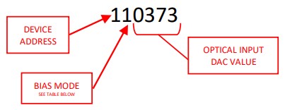 Optical Input DAC Value
The optical input DAC value is a representation of the optical input power to the feedback photodiode. If your unit was ordered with the photodiode installed, the calibration data for the PD has been provided for you. You can calculate the optical power using the following formula:
Optical Power (μW) = Optical Power Coefficient x DAC Value
Bias Voltage DAC Value
The bias voltage DAC value is a representation of the actual bias output voltage. You can calculate the bias voltage and/or its DAC value using the formulas below.
Bias Voltage (V) = VMAX – (Voltage Coefficient x DAC Value)
or
DAC Value = (VMAX – Voltage) / Voltage Coefficient
The voltage coefficient can be found on the test report shipped with each BCB-4 unit, or can be calculated below:
Voltage Coefficient = (Vmax- Vmin)/16384
Vpi Voltage DAC Value
The Vpi voltage DAC value is a representation of the actual voltage. You can calculate the Vpi voltage and/or the DAC value using the formulas below.
Vpi (V) = Voltage Coefficient x DAC Value
or
DAC Value = Vpi (V) / Voltage Coefficient
SET COMMANDS
RESET[ADD]{CR/LF} – Resets the device.
SETADD:X{CR/LF} – Set the device address for RS-485 communication. Range: 0 – 9. Default: 1.
Example: SETADD:1{CR/LF} – Sets the device address to 1.
SET[ADD]M:X{CR/LF} – Set the device bias mode (see table below); 1 digit required.
Example: SET2M:1{CR/LF} – Sets the bias mode to Q+ for the device at address 2.
| MODE # | BIAS MODE |
| 1 | Q+ |
| 2 | Q- |
| 3 | MAX |
| 4 | MIN |
| 5 | Manual Bias without dither |
| 6 | Manual Bias with dither |
SET[ADD]V:XXXXX{CR/LF} – Set the bias voltage DAC value when the device is in manual bias mode (5).
Range: 00000 – 16383 (00000 ≈ Vmax and 16383 ≈ Vmin).
5-digit field width required, pad with zeros on left.
Example: SET1V:00000{CR/LF} – Sets the bias voltage to about Vmax for the device at address 1. Vmax is +11V for “-11” version, and +15V for “-15” version.
SETOFS[1/2/3/4]:+/-XXXX{CR/LF} – Set the correction value of the readback DAC value for each bias mode.
Range: ±0000 – 1000; digit before the colon corresponds to the bias mode (see chart above).
Sign is required; 4-digit field width required, pad with zeros on left. All offset values are default to 0.
Example: SETOFS1:+0039{CR/LF} – Sets the correction value to +39 for bias mode 1 (Q+).
JUMP[ADD]:+/-{CR/LF} – Move the bias voltage to an adjacent bias point by jump 2Vpi; “+” will jump to an adjacent bias point with increased bias voltage and “-“ with decreased bias voltage. The Vpi value shall be set before this command can be used. If the “jump” is successful, the device will return “SET”. If the new bias voltage point is too close to or outside of the bias range of the BCB-4, the device will return “SET ERROR” and remain at the current bias point. In that case, use the opposite jump direction.
![]() Optilab, LLC
Optilab, LLC
600 E Camelback Rd, Phoenix, AZ 85012
Phone: 602-343-1496,
Fax: 602-343-1489,
Email: sales@optilab.com
Documents / Resources
 |
Optilab BCB-4 Automatic Bias Controller [pdf] User Manual BCB-4, BCB-4 Automatic Bias Controller, Automatic Bias Controller, Bias Controller, Controller |