opengear OG-DA-AV Analog Distribution Amplifiers
WHAT’S IN THE BOX
OG-DA-AV-SET-1
- 1 x OG-DA-AV-MB
- 1 x OG-DA-AV-RM
OG-DA-AV-SET-2
- 2 x OG-DA-AA-MB
- 1 x OG-DA-AA-RM2
Key Features
- OGX/3.0 card-based form factor.
- Dashboard control enabled
- Easy and intuitive seven-segment LED display to represent gain adjusments
- 1×8 analog video distribution amplifier with loopout
- Can fit up to 20 OG-DA-AV-MB in 2 RU with high density rear modules
- Supports card-edge control of EQ and gain control
- Supports input cable length of 1,000 ft (300m)
- Input provides differential or single-ended and hi-Z looping or card terminated operations
- Signal path can be set as DC or AC coupled
- User-selectable input clamping
- Low power consumption – less than 10 W.
- 5-year limited warranty
Specifications
| DESCRIPTION | Analog audio distribution amplifier |
| Product Name | OG-DA-AV |
| INPUT | |
| Impedance | User selectable as hi-Z looping or card-terminated 75Ω |
| Level | 1 Vp-p , nominal |
| Modes | User selectable as differential/single-ended and AC or DC
coupled |
|
| PERFORMACE | ||
| Gain | 9dB | |
| OUTPUT | ||
| Impedance | 75Ω | |
| Level | 1 Vp-p , nominal | |
| GENERAL | ||
| Power Requirements | +12 V, 210 mA idling | |
| Dimensions | 325mm x 76.8mm | |
| Weight | 135g | |
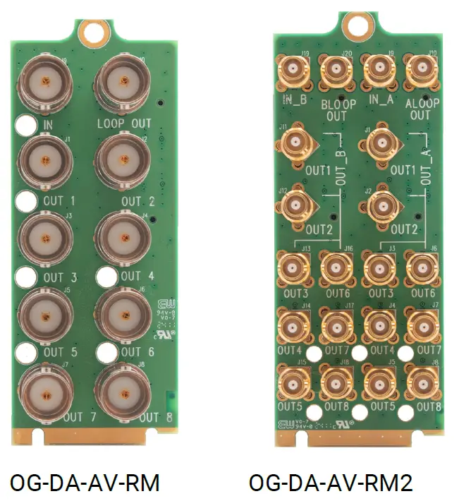
Rear Modules
Dashboard Control
Getting Started
The Dashboard software is design to allow you to quickly access the feature sets of openGear form factor cards on a simple User Interface. This section will help you get up and running as quickly as possible.
Running Dashboard
Before you can successfully run the Dashboard software for the first time you must first download it from https://www.opengear.tv/frame-and-control/control-system/download/. Run the downloaded setup file and choose an appropriate installation location on your computer’s storage. Now you can run the Dashboard by double clicking on the Dashboard icon.
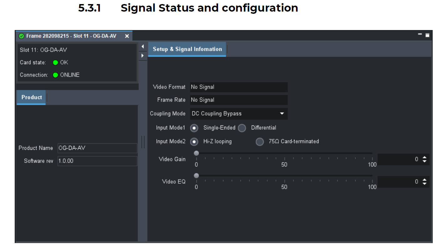
OG-DA-AV Dashboard
OG-HDM2.0-1×2-Dual is a very straight forward plug and play card. The Dashboard interfaces are as follows:
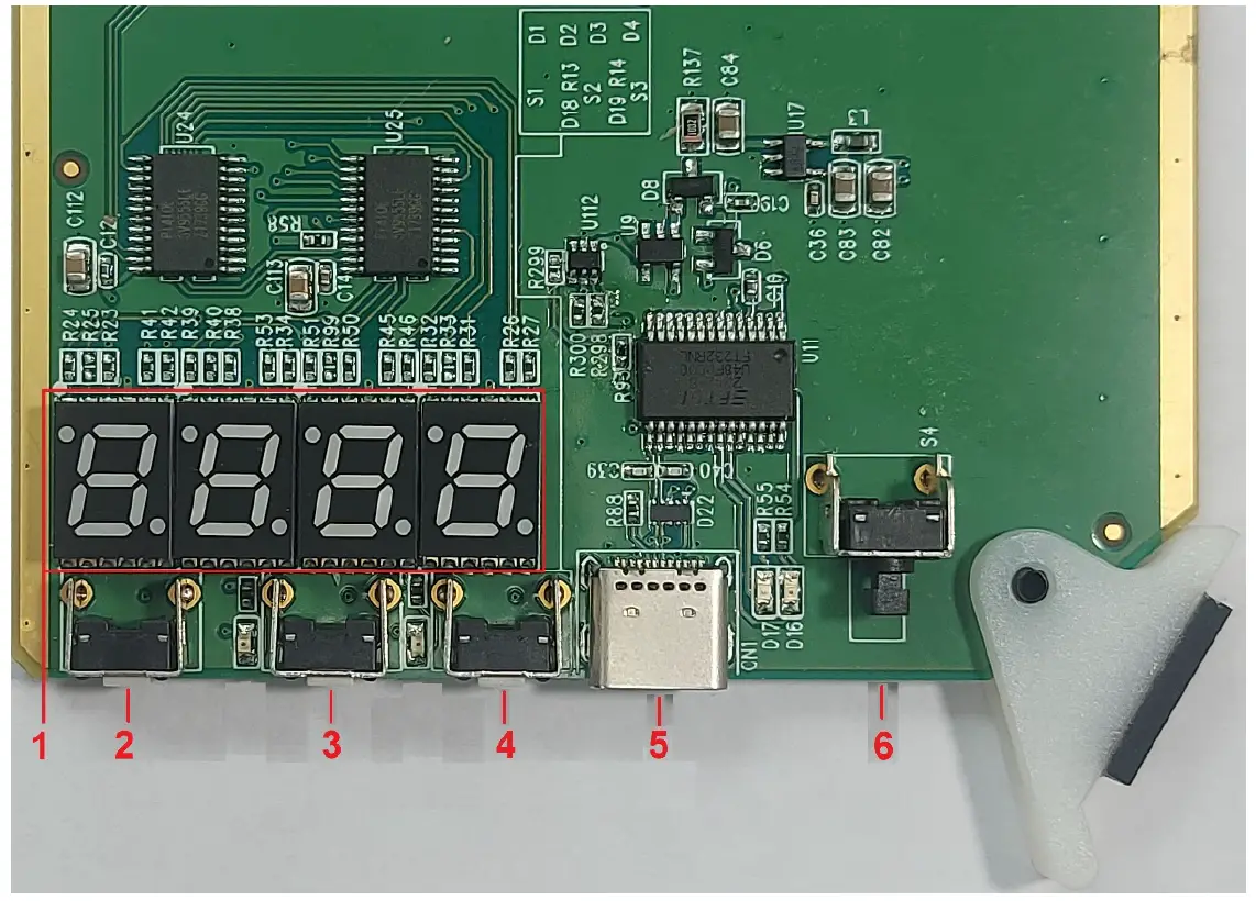
- 7-segmented Display
Display Information The seven-segment display is generally in a non-display state. Pressing the menu button will wake up the seven-segment display to show information or enter operation mode. If there is no operation for 3 minutes, the seven-segment display will return to the non-display state. The first digit on the left indicates the menu page, while the remaining three digits represent functions or values. - Menu Button
Wakes up the seven-segment display to show information, enter operation mode, or select an operation option. - Up Button
Increases the value of the selected option. - Down Button
Increases the value of the selected option. - USB Type-C for Software Updates
Used for updating the software. - Reset Button
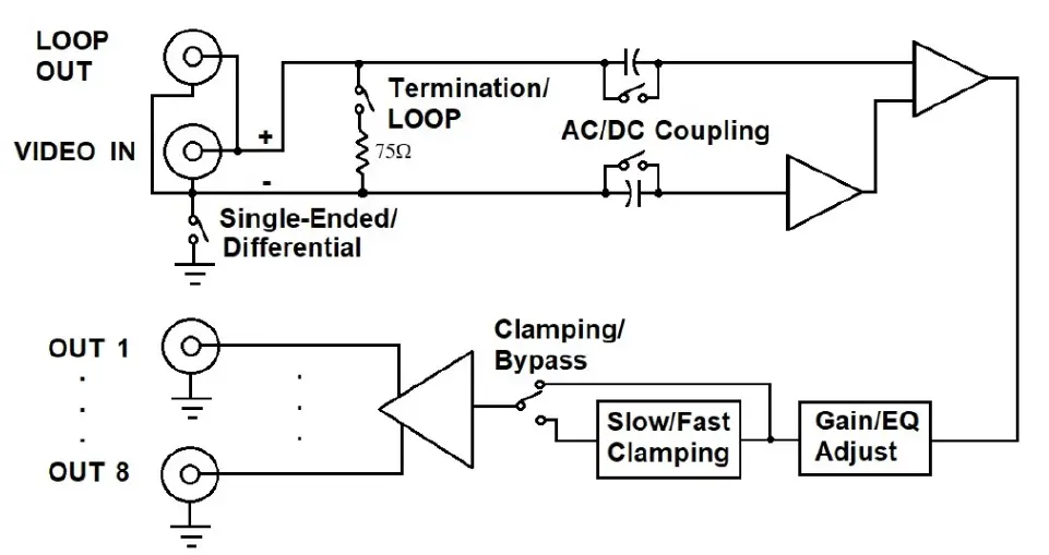
Functional Block Diagram
Onboard Operations
Menu 1
Input loop or Termination (Loop setting is generally used for connecting multiple cards in series. Termination is typically used for a single card or for the last card in a series connection)
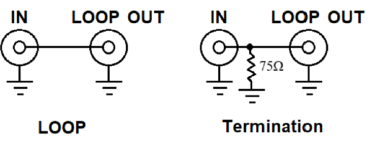
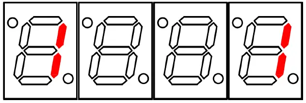
As shown in the figure below, Menu 1
Function set to 0 indicates that the input is configured as Loop (hi-Z) input.

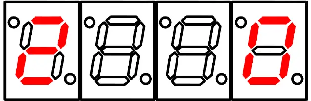
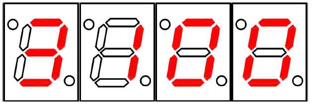
As shown in the figure below, Menu 1
Function set to 1 indicates that the input is configured as Termination (75Ω) input.
Menu 2
Gain Adjustment
The adjustment range is from 0 to 100, with each unit corresponding to approximately 9.4 to 9.5 mV.
- 0 = 0V
- 1 = 0.1040V
- 100 = 1.0398V
This range translates from 0V to 1V, representing a gain of 0 dB to 3 dB.
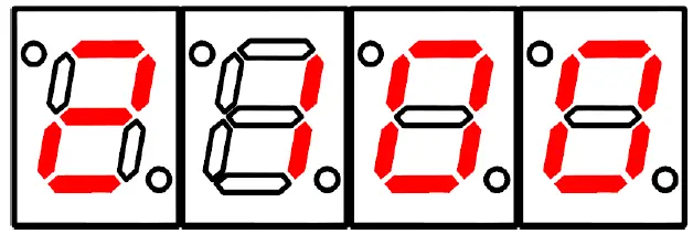
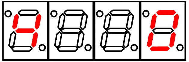
As shown in the figure below, Menu 2
Value set to 0.
As shown in the figure below, Menu 2
Value set to 100.
When a signal is transmitted through a long cable, signal loss occurs. If the video becomes dim, the Gain value can be adjusted to compensate for the signal loss, making the video brighter.
Menu 3
EQ Value Adjustment
The adjustment range is from 0 to 100, with each unit corresponding to approximately 9.4 to 9.5 mV.
- 0 = 0V
- 1 = 0.1040V
- 100 = 1.0398V
This range translates from 0V to 1V, representing a gain of 0 dB to 20 dB at 120 MHz.
As shown in the figure below, Menu 3
Value set to 0.
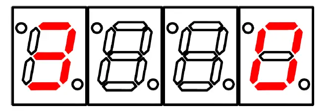
As shown in the figure below, Menu 3
Value set to 100.
When a signal is transmitted through a long cable, signal loss occurs. If the video becomes blurry, the EQ value can be adjusted to compensate for the signal loss, making the video clearer.
Menu 4
Input Single-Ended or Differential
Set the input to either single-ended or differential. This setting applies to the BNC connectors labeled “IN” on the backplane.
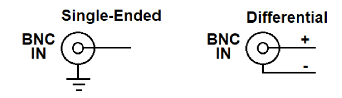
As shown in the figure below, Menu 4
Function set to 0 indicates that the input is configured as Single-Ended input.
As shown in the figure below, Menu 4
Function set to 1 indicates that the input is configured as Differential input.
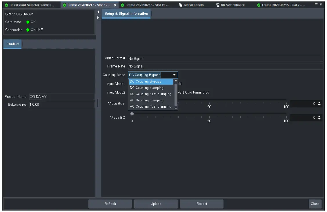
As shown in the figure below, Menu 5
Function set to 1 indicates DC Coupling Clamping (The input signal, after passing through the EQ/Gain circuit, is connected to the slow clamping circuit before being sent to the 1×8 splitter output inside the card).
As shown in the figure below, Menu 5
Function set to 2 indicates DC Coupling Fast Clamping (The input signal, after passing through the EQ/Gain circuit, is connected to the fast-clamping circuit before being sent to the 1×8 splitter output inside the card).
Appendex A
COPYRIGHT, TRADEMARK, and REGISTRATION
All rights reserved by APANTAC LCC, Beaverton, Oregon, USA. No part of this document may be reproduced in any form or by any means without written permission from the product manufacturer. Changes are periodically made to the information in this document. They will be incorporated in subsequent editions. The product manufacturer may make improvements and/or changes in the product described in this document at any time. All other trademark(s), copyright(s), and registered technologies mentioned in this document are the properties of their repective owner(s).
WARRANTY STATEMENT
Apantac LLC (herein after referred to as “Apantac”) warrants to the original purchaser of the products manufactured by Apantac (the “Product,”) will be free from defects in material and workmanship for a period of three (3) year from the date of shipment of the Product to the purchaser. If the Product proves to be defective during the three (3) year warranty period, the purchaser’s exclusive remedy and Apantac’s sole obligation under this warranty is expressly limited, at Apantac’s sole option, to:
- repair the defective Product without charge for parts and labor or,
- provide a replacement in exchange for the defective Product or,
- if after a reasonable time, is unable to correct the defect or provide a replacement Product in good working order, then the purchaser shall be entitled to recover damages subject to the limitation of liability set forth below.
Limitation of Liability
Apantac’s liability under this warranty shall not exceed the purchase price paid for the defective product. In no event shall Apantac be liable for any incidental, special or consequential damages, including without limitation, loss of profits for any breach of this warranty. If Apantac replaces the defective Product with a replacement Product as provided under the terms of this Warranty, in no event will the term of the warranty on the replacement Product exceed the number of months remaining on the warranty covering the defective Product. Equipment manufactured by other suppliers and supplied by Apantac carries the respective manufacturer’s warranty. Apantac assumes no warranty responsibility either expressed or implied for equipment manufactured by others and supplied by Apantac.
This hardware warranty shall not apply to any defect, failure, or damage:
- Caused by improper use of the Product or inadequate maintenance and care of the Product.
- Resulting from attempts by those other than Apantac representatives to install, repair, or service the Product.
- Caused by installation of the Product in a hostile operating environment or connection of the Product to incompatible equipment.
APANTAC LLC, 10200 SW ALLEN BLVD, BEAVERTON, OR 97005
INFO@APANTAC.COM,
TEL: +1 503 968 3000,
FAX: +1 503 389 7921
Documents / Resources
 |
opengear OG-DA-AV Analog Distribution Amplifiers [pdf] User Manual OG-DA-AV Analog Distribution Amplifiers, OG-DA-AV, Analog Distribution Amplifiers, Distribution Amplifiers, Amplifiers |


