![]() Quick Start Guide
Quick Start Guide
IMX91LP4EVK-11CM
i.MX 91 Applications Processor
About the i.MX 91 EVK
The i.MX 91 family of applications processors enables the rapid creation of new Linux-based edge devices. It excels in advanced multimedia and industrial IoT applications etc. Elevating edge intelligence, i.MX 91 processors provide a solid foundation for devices in smart factory, smart home, smart office, medical device, metering, and cost-optimized system-on-module platforms.
Specifications
Compute card:
- i.MX 91 applications processor with: – 1x Arm® Cortex®-A55
- LPDDR4 16-bit 2GB
- eMMC 5.1, 32GB
- Power Management IC (PMIC)
- Power Measurement ADC
Base board:
- MicroSD 3.0 card slot
- Two USB 2.0 C connector
- One USB 2.0 C for Debug
- One USB C PD only
- M.2 Key-E for Wi-Fi/BT/802.15.4
- One CAN port
- Four channels for ADC
- 6-axis IMU w/ I3C support
- Two 1 Gbps Ethernet
– Port1 supports TSN
– Port2 supports ETER - I2C Expansion connector
- Audio Codec Support
- PDM MIC array support
- External RTC w/ coin cell
- 2×20 Pin Expansion I/O
Get to know the i.MX 91 EVK


Getting started
Unpack the kit
The i.MX 91 EVK is shipped with the items listed in Table 1.
Table 1 — Kit contents
| Item | Description |
| IMX91LP4EVK-11CM | IMX91LP4EVK-11CM board |
| Power Supply | USB C PD 45W, 5V/3A; 9V/3A; 15V/3A; 20V/2.25A supported |
| USB Type-C Cable | USB 2.0 C Male to USB 2.0 A Male |
| M.2 Module | PN: EAR00409; Wi-Fi 6 / BT 5.2 / 802.15.4 support, basing on NXP IW612 |
| Software | Linux BSP image programmed in eMMC |
| Documentation | Quick Start Guide |
Prepare Accessories
The following items in Table 2 are recommended to run the i.MX 91 EVK.
Table 2 — Customer supplied accessories
| Item | Description |
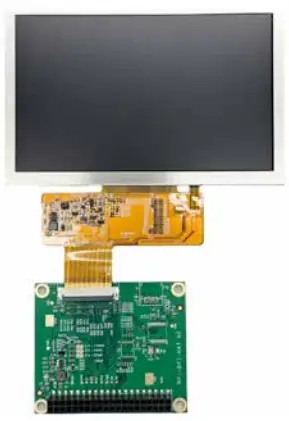
| T050RDH03-HC | Parallel LCD DISPLAY MODULE 5″ TFT 800X480 RGB |
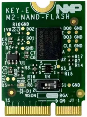
| M2-NAND-FLASH | M.2 NAND flash daughter card |
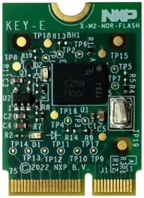
| M2-NOR-FLASH | M.2 NOR flash daughter card |
| Audio HAT | Audio expansion board with most of audio features |
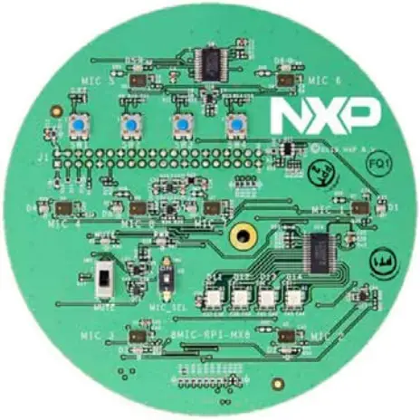
| 8MIC-RPI-MX8 | 8-microphone array proto board for voice enablement |
Download software and tools
Installation software and documentation are available at www.nxp.com/imx91evkcm. The following are available on the website:
Table 3 — Software and Tools
| Item | Description |
| Documentation | • Schematics, layout and Gerber files • Quick Start Guide • Hardware Design Guide • i.MX 91 EVK Board User Manual • Power Consumption Measurement |
| Software Development | • Linux BSPs |
| Demo Images | • Copy of the latest Linux images that are available to program on to the eMMC. • IMX91LP4EVK-11CM software can be found at nxp.com/imxsw |
Setting up the system
The following will describe how to run the pre-loaded Linux image on the MCIMX91-EVK (i.MX 91).
- Confirm boot switches
The boot switches should be set to boot from “eMMC”, SW1301[4-1] (Figure 1) are used for boot, See table below:BOOT Device SW1301[1-4] eMMC/uSDHC1 0000 Note: 1 = ON 0 = OFF
- Connect USB debug cable
Connect the UART cable into the port JP1401 (Figure 1). Connect the other end of the cable to a PC acting as a host terminal.
UART connections will appear on the PC, The third port will be used as A55 core system debugging.
Open the terminal window (i.e., Hyper Terminal or Tera Term), choose the right COM port number and apply the following configuration.
• Baud rate: 115200bps
• Data bits: 8
• Parity: None
• Stop bits: 1 - Connect parallel panel display
Plug the parallel LCD panel (T050RDH03-HC) into J1001 2×20 PIN header. - Connect mouse
Connect the mouse to the USB2 C port connector J302 through USB C OTG cable. - Connect power supply
Connect the USB C PD power supply to J301, then power up the board by SW301 switch.
- Board boot up
As the board boots up, you will see 4 penguins appear in the upper left-hand corner of the monitor, and then you will see the Linux terminal Icon on the top left and timer on right top corner . Congratulations, you are up and running.
Run “Go Point for i.MX Applications Processors” application to explore the preinstalled demos. The NXP Logo is displayed on the top left-hand corner of screen, start the demo launcher by clicking this logo. Refer to user guide for details: https://www.nxp.com/webapp/Download?colCode=GPNTUG.vz
Additional information
Boot Switches
SW1301[1-4] is the boot configuration switch, the default boot device is eMMC/uSDHC1, as shown in Table 4. If you want to try other boot devices, you need to change the boot switches to corresponding values as listed in Table 4.
Note: 1 = ON 0 = OFF
Table 4 — Boot device settings
| BOOT MODE | SW1301-4 | SW1301-3 | SW1301-2 | SW1301-1 |
| From internal fuses | 0 | 0 | 0 | 1 |
| Serial Downloader | 0 | 0 | 1 | 1 |
| USDHC1 8-bit eMMC 5.1 | 0 | 0 | 0 | 0 |
| USDHC2 4-bit SD3.0 | 0 | 0 | 1 | 0 |
| FlexSPI Serial NOR | 0 | 1 | 0 | 1 |
| FlexSPI Serial NAND 2K page | 0 | 1 | 1 | 1 |
| Reserved | 0 | 1 | 0 | 0 |
| Reserved | 0 | 1 | 1 | 0 |
Do more with Accessory Boards
| Parallel LCD: T050RDH03-HC LCD DISPLAY MODULE 5” TFT 800X480, RGB, 120.7 mm x 75.8 mm |
M2-NAND-FLASH QSPI NAND flash daughter card with M.2 interface. Winbond 256MB W25N02KWZEIR (WSON8X6) + GigaDevice 256MB GD5F2GM7REBIG (BGA24) |
 |
 |
| M2-NOR-FLASH QSPI NOR flash daughter card with M.2 interface. Micron64MB MT25QU512ABB8E12-0AAT(BGA24) |
WiFi/BT/IEEE802.15.4 M.2 Module (LBES5PL2EL) Wi-Fi 6, IEEE 802.11a/b/g/n/ac + Bluetooth 5.2 BR/EDR/LE + IEEE802.15.4, NXP IW612 chipset |
 |
 |
| Audio Board: MX93AUD-HAT Audio expansion board with most of audio features |
Microphone Board: 8MIC-RPI-MX8 8-microphone array proto board for voice enablement. |
 |
 |
Support
Visit www.nxp.com/support for a list of phone numbers within your region.
Warranty
Visit www.nxp.com/warranty for complete warranty information.
This device complies with Part 15 of the FCC Rules. Operation is subject to the following two conditions:
(1) This device may not cause harmful interference, and
(2) This device must accept any interference received, including interference that may cause undesired operation.
Attention that changes or modification not expressly approved by the party responsible for compliance could void the user’s authority to operate the equipment.
Note: This product has been tested and found to comply with the limits for a Class B digital device, pursuant to Part 15 of the FCC Rules. These limits are designed to provide reasonable protection against harmful interference in a residential installation. This product generates, uses, and can radiate radio frequency energy and, if not installed and used in accordance with the instructions, may cause harmful interference to radio communications. However, there is no guarantee that interference will not occur in a particular installation.
If this product does cause harmful interference to radio or television reception, which can be determined by turning the equipment off and on, the user is encouraged to try to correct the interference by one or more of the following measures:
- Reorient or relocate the receiving antenna.
- Increase the separation between the equipment and receiver.
- Connect the equipment into an outlet on a circuit different from that to which the receiver is connected.
- Consult the dealer or an experienced radio/TV technician for help.
This equipment should be installed and operated with a minimum distance 20cm between the radiator and your body.
www.nxp.com/iMX91EVKCM
NXP and the NXP logo are trademarks of NXP B.V.
All other product or service names are the property of
their respective owners. © 2024 NXP B.V.
Document Number: 91EVKCMQSG REV 0
MPN : IMX91LP4EVK-11CM
Aras ID : 91450
Documents / Resources
 |
NXP i.MX 91 Applications Processor [pdf] User Guide IMX91LP4EVK-11CM, i.MX 91 Applications Processor, i.MX 91, Applications Processor, Processor |