1. Introduksjon
This manual provides essential information for the installation, operation, maintenance, and troubleshooting of the Juniper Networks EX4200-24P 24-Port Power over Ethernet (PoE) Ethernet Switch. The EX4200-24P is designed to provide high-performance, reliable network connectivity for enterprise and data center environments, offering 24 Gigabit Ethernet ports with PoE+ capabilities and Layer 3 features.
2. Sikkerhetsinformasjon
Følg følgende sikkerhetsregler for å forhindre skader og materielle skader:
- Sørg for riktig jording av enheten.
- Ikke bruk bryteren i våte eller svært fuktige omgivelser.
- Koble fra strømmen før du utfører vedlikeholds- eller installasjonsprosedyrer.
- Use only approved power cords and accessories.
- Sørg for tilstrekkelig ventilasjon rundt bryteren for å forhindre overoppheting.
3. Pakkens innhold
Kontroller at pakken inneholder følgende elementer:
- Juniper Networks EX4200-24P Ethernet Switch
- Strømledning
- Rackmonteringssett (braketter, skruer)
- Konsollkabel (RJ-45 til DB-9)
- Dokumentasjon (hurtigstartveiledning, sikkerhetsinformasjon)
Note: Contents may vary based on the specific renewed product offering.
4. Fysisk overview
4.1 Frontpanel
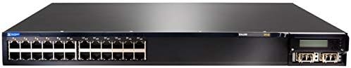
Figure 4.1: Front Panel of EX4200-24P Switch. This image displays the front of the Juniper Networks EX4200-24P switch, featuring 24 RJ-45 Gigabit Ethernet ports, each with LED indicators, and four SFP+ uplink ports on the right side, along with a small LCD display and control buttons.
The front panel of the EX4200-24P switch includes:
- 24 x 10/100/1000BASE-T Ethernet-porter: RJ-45 connectors for network devices. Each port supports Power over Ethernet Plus (PoE+).
- Portstatuslamper: Indicators for link status, activity, and PoE status for each port.
- Uplink Module Slot: Typically houses 4x SFP/SFP+ ports for high-speed uplinks to other network devices or the core network.
- LCD-skjerm: Provides system status, configuration information, and error messages.
- Kontrollknapper: Used to navigate and interact with the LCD display menu.
- Systemstatuslamper: Indicators for power, alarm, and system status.
4.2 Bakpanel

Figur 4.2: Vinklet View of EX4200-24P Switch. This image provides an angled perspective of the Juniper Networks EX4200-24P switch, highlighting the front panel with its 24 Ethernet ports and uplink module, and giving a partial view of the side chassis. The rear panel, not fully visible in this image, typically contains power input, fan modules, and a console port.
The rear panel typically includes:
- AC strømkontakt: For tilkobling av strømledningen.
- Konsollport (RJ-45): For local management and initial configuration using a serial connection.
- USB-port: For software upgrades or configuration backup/restore.
- Viftemoduler: Removable fan trays for cooling.
5. Oppsett og installasjon
5.1 Forberedelse av stedet
Before installation, ensure the installation site meets the following requirements:
- Miljø: Maintain an ambient temperature between 0°C and 45°C (32°F and 113°F) and relative humidity between 10% and 85% (non-condensing).
- Makt: A dedicated power outlet with proper grounding is recommended.
- Ventilasjon: Ensure at least 5 cm (2 inches) of clearance at the front and rear for airflow.
5.2 Rackmontering
The EX4200-24P is designed for installation in a standard 19-inch equipment rack.
- Attach the provided rack-mount brackets to the sides of the switch using the supplied screws.
- Juster bryteren med stativstolpene og fest den med passende stativskruer.
5.3 Strømtilkobling
- Connect one end of the power cord to the AC power connector on the rear panel of the switch.
- Koble den andre enden av strømledningen til en jordet stikkontakt.
- The switch will power on automatically. Observe the system status LEDs for initial boot-up.
5.4 Nettverkstilkoblinger
- Connect Ethernet cables from your network devices (computers, IP phones, wireless access points) to the RJ-45 ports on the front panel.
- For uplink connections to other switches or routers, insert appropriate SFP/SFP+ transceivers into the uplink module slot and connect fiber or copper cables as required.
- For initial configuration, connect a console cable from your management workstation to the console port on the rear panel.
6. Betjening av bryteren
6.1 Power On and Initial Boot
Once connected to power, the switch will begin its boot sequence. The system status LEDs will indicate the boot progress. The LCD display will show system information during startup.
6.2 LED-indikatorer
Overvåk LED-lysene på frontpanelet for å forstå bryterens driftsstatus:
- System LED: Indicates overall system health (e.g., green for normal operation, amber for minor alarm, red for major alarm).
- Strøm LED: Indikerer strømstatus.
- LED-lamper for portkobling/aktivitet:
- Helt grønt: Link etablert.
- Blinker grønt: Activity on the port.
- Av: Ingen lenke.
- PoE Status LEDs: Indicate Power over Ethernet status for PoE-enabled ports.
6.3 Tilgang til grunnleggende konfigurasjon
The switch can be configured via the command-line interface (CLI) through the console port or remotely via Telnet/SSH after initial IP configuration. Refer to the Juniper Networks documentation for detailed CLI commands and configuration guides.
- Konsollport: Use a terminal emulator (e.g., PuTTY) with settings: 9600 baud, 8 data bits, no parity, 1 stop bit, no flow control.
- Web Grensesnitt: Some Juniper switches offer a web-based management interface. Check your specific firmware version for availability and default access details.
7. Vedlikehold
7.1 Rengjøring
Regelmessig rengjøring bidrar til å opprettholde optimal ytelse og forlenger bryterens levetid.
- Power off and disconnect the switch before cleaning.
- Bruk en myk, tørr klut til å tørke av utsiden.
- Use compressed air to clear dust from ventilation openings and fan modules.
- Ikke bruk flytende rengjøringsmidler eller aerosolrengjøringsmidler direkte på bryteren.
7.2 firmwareoppdateringer
Sjekk Juniper Networks-kundestøtten med jevne mellomrom website for the latest firmware updates. Firmware updates can provide new features, performance improvements, and security patches. Follow the instructions provided with the firmware package for proper installation.
7.3 Miljøhensyn
Ensure the switch operates within its specified temperature and humidity ranges. Avoid blocking ventilation ports and ensure proper airflow to prevent overheating, which can lead to system instability or failure.
8. Feilsøking
Denne delen inneholder løsninger på vanlige problemer du kan støte på.
8.1 Ingen strøm
- Kontroller at strømledningen er ordentlig koblet til både bryteren og stikkontakten.
- Sjekk om strømuttaket fungerer ved å koble til en annen enhet.
- Ensure the power supply unit (if modular) is properly seated.
8.2 Ingen kobling på porten
- Sjekk Ethernet-kabeltilkoblingen i begge ender. Prøv en annen kabel.
- Kontroller at den tilkoblede enheten er slått på og fungerer som den skal.
- Check the port configuration on the switch (e.g., speed, duplex settings).
8.3 Problemer med nettverkstilkobling
- Confirm the switch has a valid IP address and network configuration.
- Sjekk for IP-adressekonflikter på nettverket.
- Verify VLAN configurations if applicable.
- Start svitsjen og tilkoblede enheter på nytt.
8.4 Fabrikkinnstilling
A factory reset will erase all configurations and restore the switch to its default settings. Consult the Juniper Networks documentation for the specific procedure for the EX4200 series, as it typically involves a specific command sequence via the console port.
9. Tekniske spesifikasjoner
| Trekk | Spesifikasjon |
|---|---|
| Modell | EX4200-24P |
| Merke | Juniper Networks |
| Antall porter | 24 x 10/100/1000BASE-T (PoE+) |
| Grensesnitttype | RJ45 |
| Produktdimensjoner (LxBxH) | 23 x 22.75 x 11 tommer (58.42 x 57.78 x 27.94 cm) |
| Varevekt | 23.1 pund (10.48 kg) |
| Koffertmateriale | Plast |
| Øvre temperaturvurdering | 45 grader Celsius |
| UPC | 647213692099 |
| ASIN | B07PFLPRX6 |
10. Garantiinformasjon
This Juniper Networks EX4200-24P switch is offered as a renewed product. Warranty coverage for renewed products is typically provided by the seller, "Network Hardware Depot" in this case, or the Amazon Renewed program, not directly by Juniper Networks.
- Seller's Return Policy: The seller offers a return policy, typically 30 days for refund/replacement.
- Utvidede beskyttelsesplaner: Additional protection plans may be available for purchase through Amazon or third-party providers.
- For specific warranty details and terms, please refer to the purchase agreement or contact the seller directly.
Juridisk ansvarsfraskrivelse fra selger: "We DO NOT accept RMA's or Returns for Non Defective Items. Any merchandise returned for repair and found NOT to be defective by our technicians will have a 25% restocking fee. There will be no exception to this policy. By placing a bid or order with us you have entered into a binding agreement that you acknowledge and accept our procedures. Additional warranty length is available, contact us directly for more details."
11. Støtte
For technical assistance, further documentation, or advanced configuration guides, please refer to the official Juniper Networks support website. For issues related to the renewed product's condition or seller-specific policies, contact the seller directly.
- Juniper Networks Support: www.juniper.net/us/en/support.html
- Selgerkontakt: Refer to your Amazon order details for seller contact information (Network Hardware Depot).


