1. Product voorbijview
The EPEVER Tracer BN Series MPPT Solar Charge Controller is an advanced, efficient, and multi-functional device designed for off-grid solar systems. It utilizes Maximum Power Point Tracking (MPPT) technology to maximize energy harvest from solar panels, ensuring optimal charging for your battery bank. This controller is suitable for various applications, including telecommunication base stations, household systems, street lighting, and wilderness monitoring systems.
Belangrijkste kenmerken zijn:
- Advanced MPPT technology with tracking efficiency no less than 99.5% and maximum conversion efficiency of 98%.
- Reliable automatic limit function of maximum PV input power, preventing overload under any circumstances.
- Brede MPP-bedrijfsvoltage bereik.
- Gemaakt van gegoten aluminium voor uitstekende warmteafvoer.
- 12/24VDC automatisch systeem voltage identificatie.
- Multiple load control modes: manual control, light ON/OFF, light ON+Timer, and time control.
- Supports 4 charging options: Sealed, Gel, Flooded, and User-defined.
- PC monitoring and external display unit (like MT50) connectivity for real-time data checking and parameter setting, with software upgrade support.
- Modbus communication protocol interface for expanded applications and monitoring.
2. Productcomponenten
Familiarize yourself with the main components and interfaces of the Tracer BN series solar charge controller:

Figure 2.1: Controller Components Overview
This image displays the EPEVER Tracer BN Series Solar Charge Controller with key components labeled, including the Heat Sink, Button, Charging LED indicator, Battery LED indicator, RTS port, RS485 Port, Solar Terminal, Battery Terminal, and Load Terminal.
- Koellichaam: Dissipates heat generated during operation to maintain optimal performance.
- Knop: Used for manual control of the load and navigating settings.
- LED-indicator opladen: Shows the status of PV (solar panel) charging.
- Batterij LED-indicator: Displays the battery charging status.
- RTS (Remote Temperature Sensor) Port: Connects an optional remote temperature sensor for accurate battery temperature compensation.
- RS485-poort: Communication interface for connecting to PC, MT50 remote meter, WiFi, or Bluetooth modules.
- Solar Terminal (PV): Connects to the solar panel array.
- Battery Terminal (BATT): Wordt aangesloten op de accubank.
- Laadterminal: Aansluiting voor gelijkstroombelastingen.
3. Installatie en installatie
Proper installation is crucial for the safe and efficient operation of your solar charge controller. Please follow these steps carefully:
3.1 Uitpakken en eerste inspectie
Video 3.1: Uitpakken en component overview
This video demonstrates the unboxing process of the EPEVER Tracer BN MPPT Solar Charge Controller and provides a visual overview of its main components and ports, including the PV charging LED indicator, battery charging LED indicator, button, PV terminals, battery terminals, load terminals, heat sink, RTS port, and RS485 port.
- Carefully open the packaging and remove the controller and any accessories.
- Inspect the controller for any visible damage. If damage is found, contact your supplier.
- Zorg ervoor dat alle genoemde componenten aanwezig zijn.
3.2 bedradingsverbindingen
Belangrijke veiligheidsopmerking: While wiring the controller, ensure that the circuit breaker or fuse is niet closed. Verify that the positive ("+") and negative ("-") leads are connected correctly to prevent damage to the controller or other components.
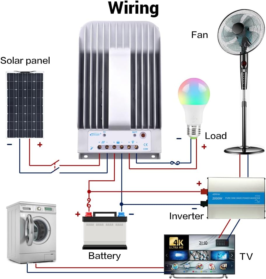
Figure 3.2: Typical System Wiring Diagram
This diagram illustrates a typical solar power system setup, showing the connection of the solar panel to the controller, the controller to the battery, and the controller to various DC and AC loads via an inverter. Ensure correct polarity for all connections.
The connection order is critical:
- Sluit de batterij aan: First, connect the battery to the controller's battery terminals. Ensure correct polarity (positive to positive, negative to negative). The controller will automatically detect the system voltage (12V/24V). The controller supports Lead-acid Batteries (Sealed, AGM, Gel, Flooded) and User-defined settings.
- De belasting aansluiten: Sluit vervolgens uw DC-belastingen aan op de belastingsaansluitingen van de controller.
- Connect the Solar Panel (PV): Sluit tot slot de zonnepanelen aan op de PV-aansluitingen van de controller.
The disconnection order is the reverse: PV -> Load -> Battery.
Refer to the following table for recommended wire sizes based on controller model:
| Model | Wire Size (AWG/mm²) |
|---|---|
| Tracer1215BN | 12AWG (4 mm²) |
| Tracer2215BN | 8AWG (10 mm²) |
| Tracer3215BN | 6AWG (16 mm²) |
| Tracer4215BN | 4AWG (25 mm²) |
4. Gebruiksaanwijzing
Once the controller is correctly wired and powered, it will begin operating automatically. The LED indicators provide visual feedback on the system status.
4.1 Belastingcontrole
The controller offers various load control modes. In manual control mode, you can toggle the load on or off using the controller's button.
Video 4.1: Load Manual Mode Operation
This video segment demonstrates how to manually turn the load ON/OFF by pressing the 'ENTER' button on the controller when it is in load manual mode.
Other load control modes (Light ON/OFF, Light ON+Timer, Time Control) can be configured using an external display unit (like MT50) or PC/APP software connected via the RS485 port.
4.2 Monitoring and Parameter Setting
The controller supports various accessories for enhanced monitoring and parameter adjustment:

Figure 4.2: Controller with Communication Accessories
This image illustrates how the solar charge controller can be connected to various communication accessories such as the MT50 remote meter, eBox-WIFI-01 for WiFi monitoring, eBox-BLE-01 for Bluetooth monitoring, and a PC via a USB to RS485 cable for detailed system management.
Optional accessories for monitoring and control:
| Accessoire | Beschrijving |
|---|---|
| Remote Temperature Sensor (RTS300R47K3.81A) | Acquisition of battery temperature for temperature compensation of control parameters. The standard length of the cable is 3m (can be customized). The RTS300R47K3.81A connects to the port (4th) op de controller. OPMERKING: If the temperature sensor is short-circuited or damaged, the controller will be charging or discharging at the default temperature 25 °C. |
| USB to RS485 cable (CC-USB-RS485-150U) | USB to RS-485 converter used to monitor each controller on the network using Solar Station PC software. The length of cable is 1.5m. The CC-USB-RS485-150U connects to the RS-485 Port on the controller. |
| OTG cable (OTG-12CM) | Used to connect a mobile communication cable and able to achieve real-time monitoring of the controller and modification of the parameters by using mobile APP software. |
| Remote Meter (MT50) | MT50 can display various operating data and fault of the system. The information can be displayed on a backlit LCD screen, the buttons are easy-to-operate, and the numeric display is readable. |
| WiFi Serial Adapter (eBox-WIFI-01) | After the controller is connected with the eBox-WIFI-01 through the standard Ethernet cable (parallel cable), the operating status and related parameters of the controller can be monitored by the mobile APP software through WiFi signals. |
| RS485 to Bluetooth Adapter (eBox-BLE-01) | After the controller is connected with the eBox-BLE-01 through the standard Ethernet cable (parallel cable), the operating status and related parameters of the controller can be monitored by the mobile APP software through Bluetooth signals. |
| Logger (eLOG01) | Nadat de controller is verbonden met de eLOG-01 via de RS485-communicatiekabel, kan deze de bedrijfsgegevens van de controller registreren of de realtime bedrijfsstatus van de controller via pc-software bewaken. |
OPMERKING: For setting and operation of accessories, please refer to their specific instructions.
5. Onderhoud
Regelmatig onderhoud zorgt voor een lange levensduur en optimale prestaties van uw zonne-laadregelaar:
- Schoonheid: Houd de controller schoon en vrij van stof en vuil. Gebruik een droge doek om de buitenkant af te vegen.
- Verbindingen: Controleer regelmatig of alle bedradingsverbindingen goed vastzitten. Losse verbindingen kunnen oververhitting en schade veroorzaken.
- Ventilatie: Ensure the heat sink fins are not obstructed to allow for proper airflow and heat dissipation.
- Omgeving: Operate the controller within its specified ambient temperature and humidity ranges.
6. Probleemoplossing
If you encounter issues with your EPEVER solar charge controller, consider the following basic troubleshooting steps:
- Geen stroom/scherm: Controleer de accuaansluitingen en zorg ervoor dat het accuvolumetage is within the controller's operating range. Verify fuses or circuit breakers are not tripped.
- Geen opladen: Zorg ervoor dat de zonnepanelen correct zijn aangesloten en voldoende zonlicht ontvangen. Controleer het ingangsvolume van de zonnepanelen.tage and current. Verify PV circuit breaker/fuse.
- Laden werkt niet: Check load connections and ensure the load is not exceeding the controller's rated current. Verify the load control mode settings.
- Abnormal LED Indicators: Refer to the full user manual for specific error codes or indicator patterns to diagnose issues.
For complex issues or persistent problems, contact technical support.
7. Technische specificaties
The following table provides detailed technical specifications for the Tracer BN series, including the 40A model (Tracer4215BN):
Video 7.1: Technical Specifications Overview
This video segment displays a table detailing the technical specifications for the Tracer BN series MPPT Solar Charge Controllers, including electrical and environmental parameters for various models (Tracer1215BN, Tracer2215BN, Tracer3215BN, Tracer4215BN).
| Item | Tracer 1215BN | Tracer 2215BN | Tracer 3215BN | Tracer 4215BN |
|---|---|---|---|---|
| Nominaal systeemvolumetage | 12 / 24VDC auto | |||
| Nominale laadstroom | 10A | 20A | 30A | 40A |
| Nominale ontladingsstroom | 10A | 20A | 20A | 20A |
| Batterij voltage bereik | 8V~32V | |||
| Maximaal PV open circuit voltage | 150V (bij minimale omgevingstemperatuur) 138V (bij een omgevingstemperatuur van 25°C) | |||
| MPP voltage bereik | Batterij voltage+2V ~ 108V | |||
| Max. PV-ingangsvermogen | 130W (12V) 260W (24V) | 260W (12V) 520W (24V) | 390W (12V) 780W (24V) | 520W (12V) 1040W (24V) |
| Zelfconsumptie | ≤60mA (12V); ≤30mA (24V) | |||
| Ontlading circuit voltagik laat vallen | ≤0.15V | |||
| Temperatuurcompensatiecoëfficiënt | -3mV/°C/2V (Standaard) | |||
| Mededeling | RS485 (RJ45-interface) | |||
| Aarding | Veel voorkomende negatieve | |||
| Ambient temperature range* | -35°C tot +55°C | |||
| Opslagtemperatuurbereik | -35°C tot +80°C | |||
| Vochtigheidsbereik | ≤95% (NC) | |||
| Behuizing | IP30 | |||
*Please operate controller at permitted ambient temperature. If over permissible range, please derate capacity accordingly.
8. Garantie en ondersteuning
EPEVER products are designed for reliability and performance. For warranty information, please refer to the documentation included with your purchase or visit the official EPEVER website. If you require technical assistance or have questions regarding your Tracer BN series solar charge controller, please contact EPEVER customer support or your authorized dealer.