![]()
Model: R311FD
Wireless 3-axis Accelerometer Sensor
Wireless 3-axis
Accelerometer Sensor
R311FD
User Manual
Copyright© Netvox Technology Co., Ltd.
This document contains proprietary technical information which is the property of NETVOX Technology. It shall be maintained in strict confidence and shall not be disclosed to other parties, in whole or in part, without written permission of NETVOX Technology. The specifications are subject to change without prior notice.
Introduction
R311FD is the LoRaWAN TM Class A device that detects three-axis acceleration and is compatible with LoRaWAN protocol. When the device moves or vibrates over the threshold value, it immediately reports the acceleration and velocity of the X, Y, and Z axes.
LoRa Wireless Technology:
LoRa is a wireless communication technology famous for its long-distance transmission and low power consumption. Compared with other communication methods, LoRa spread spectrum modulation technique greatly extends the communication distance. It can be widely used in any use case that requires long-distance and low-data wireless communications. For example, automatic meter reading, building automation equipment, wireless security systems, industrial monitoring. It has features like small size, low power consumption, long transmission distance, strong anti-interference ability, and so on.
LoRaWAN:
LoRaWAN uses LoRa technology to define end-to-end standard specifications to ensure interoperability between devices and gateways from different manufacturers.
Appearance

Main Features
- Adopt SX1276 wireless communication module
- 2 sections 3.0V CR2450 button batteries
- Detect the three-axis acceleration and velocity of the device and the voltage
- Compatible with LoRaWAN™ Class A
- Frequency-hopping spread spectrum technology
- Configuration parameters can be configured through third-party software platforms, data can be read and alarms can be set via SMS text and email (optional)
- Available third-party platform: Actility / ThingPark, TTN, MyDevices/Cayenne
- Low power consumption and long battery life
Note:
Battery life is determined by the sensor reporting frequency and other variables, please refer to http://www.netvox.com.tw/electric/electric_calc.html On this website, users can find battery lifetime for varied models at different configurations.
Set up Instruction
On/Off
| Power on | Insert batteries. (users may need a screwdriver to open); (Insert two sections of 3V CR2450 button batteries and close the battery cover.) |
| Turn on | Press any function key, and the indicator flashes once. |
| Turn off ( Restore to factory setting) |
Press and hold the function key for 5 seconds, and the green indicator flashes 20 times. |
| Power off | Remove Batteries. |
| Note: | 1. Remove and insert the battery; the device memorizes the previous on/off state by default. 2. On/off interval is suggested to be about 10 seconds to avoid the interference of capacitor inductance and other energy storage components. 3. Press any function key and insert batteries at the same time; it will enter engineer testing mode. |
Network Joining
| Never joined the network | Turn on the device to search the network. The green indicator stays on for 5 seconds: success The green indicator remains off: fail |
| Had joined the network | Turn on the device to search the previous network. The green indicator stays on for 5 seconds: success The green indicator remains off: fail |
| Fail to join the network | Suggest checking the device verification information on the gateway or consult your platform service provider. |
Function Key
| Press and hold for 5 seconds | Restore to factory setting / Turn off The green indicator flashes 20 times: success The green indicator remains off: fail |
| Press once | The device is in the network: green indicator flashes once and sends a report The device is not in the network: green indicator remains off |
Sleeping Mode
| The device is on and in the network | Sleeping period: Min Interval. When the report change exceeds the setting value or the state changes. a data report will be sent according to Min Interval. |
Low Voltage Warning
| Low Voltage | 2.4V |
Data Report
The device will immediately send a version packet report and two attribute data reports.
Data will be reported by default setting before any configuration.
Default setting:
Max Interval: 3600s
Min Interval: 3600s (The current voltage is detected every Min Interval by default.)
Battery Voltage Change: 0x01 (0.1V)
Acceleration Change: 0x03(m/s²)
R311FD Three-axis acceleration and velocity: s:
- After the three-axis acceleration of the device exceeds ActiveThreshold, a report is sent immediately to report the three-axis acceleration and velocity.
- After reporting, the three-axis acceleration of the device needs to be lower than InActiveThreshold, and the duration is greater than 5s (cannot be modified). Then, the next detection will start. If the vibration continues during this process after the report is sent, the timing will restart.
- The device sends two data packets, one is the acceleration of the three axes, and the other is the velocity of the three axes. The interval between the two packets is 10s.
Note:
- The device report interval will be programmed based on the default firmware.
- The interval between two reports must be the minimum time.
The reported data is decoded by the Netvox LoRaWAN Application Command document and http://loraresolver.netvoxcloud.com:8888/page/index
Data report configuration and sending period are as follows:
| Min Interval (Unit: second) |
Max Interval (Unit: second) |
Reportable Change | Current Change? Reportable Change |
Current Change< Reportable Change |
| Any number between 1-65535 |
Any number between 1-65535 |
Can not be 0. | Report per Min Interval |
Report per Max Interval |
ActiveThreshold and InActiveThreshold
| Formula | Active I threshold/ I nActiveThreshold = Critical value ÷ 9.8 ÷ 0.0625 s The gravitational acceleration at standard atmospheric pressure is 9.8 m/s2 * The scale factor of the threshold is 62.5 mg |
| Active Threshold | Active Threshold can be changed by ConfigureCmd Active Threshold range is 0x0003-0x0OFF (default is 0x0003); |
| InActiveThreshold | InActiveThreshold can be changed by ConfigureCmd InActiveThreshold range is 0x0002-0x0OFF (default is 0x0002) • Active Threshold and InActiveThreshold can not be the same |
| Example | Assuming that the critical value is set to be 10m/s2, the Active Threshold would be set 10/9.8/0.0625=16.32 Active Threshold would be set integer as 16. |
Calibration
The accelerometer is a mechanical structure that contains components that can move freely.
These moving parts are very sensitive to mechanical stress, far beyond solid-state electronics.
The 0g offset is an important accelerometer indicator because it defines the baseline used to measure acceleration.
After installing R311FD, users need to let the device rest for 1 minute, and then power on. Then, turn on the device and wait for the device taking 1 minute to join the network. After that, the device will automatically execute the calibration.
After calibration, the reported three-axis acceleration value will be within 1m/s2.
When the acceleration is within 1m/s2 and the velocity is within 160mm/s, it can be judged that the device is stationary.
Example of ConfigureCmd
FPort:0x07
| Bytes | 1 | 1 | Var (Fix =9 Bytes) |
| CmdID | DeviceType | NetvoxPayLoadData |
CmdID– 1 byte
DeviceType– 1 byte – Device Type of Device
NetvoxPayLoadData– var bytes (Max=9bytes)
| Description | Device | Cmd ID |
Device Type |
NetvoxPayLoadData | |||||
| Config ReportReq |
R311FD | 0 \ 0 I | OxC7 | MinTime (2bytes Unit:s) |
MaxTime (2bytes Unit:s) |
BatteryChange (lbyte Unit:0.1v) |
Acceleration Change (2byte Unit:m/s2) |
Reserved (2Bytes,Fixed Ox00) |
|
| Config ReportRsp |
Ox81 | Status (0x0Osuccess) |
Reserved (8Bytes,Fixed Ox00) |
||||||
| ReadConfig ReportReq |
0 \ 01 | Reserved (9Bytes,Fixed Ox00) |
|||||||
| ReadConfig ReportRsp |
2 | MinTime (2bytes Unit:s) |
MaxTime (2bytes Unit:s) |
BatteryChange (lbyte Unit:0.1v) |
Acceleration Change (2byte Unit:m/s2) |
Reserved (2Bytes,Fixed Ox00) |
|||
- Command Configuration:
MinTime = 1min, MaxTime = 1min, BatteryChange = 0.1v, Acceleratedspeedchange = 1m
Downlink: 01C7003C003C0100010000 003C(Hex) = 60(Dec)
Response:
81C7000000000000000000(Configuration success)
81C7010000000000000000(Configuration failure) - Read Configuration:
Downlink: 02C7000000000000000000
Response:
82C7003C003C0100010000(Current configuration)Description Device Cmd
IDDevice
TypeNetvoxPayLoadData SetActive
ThresholdReqR31 Ill) 0 \ 01 OxC7 ActiveThreshold
(2Bytes)InActiveThreshold
(2Bytes)Reserved
(5Bytes,Fixed Ox00)SetActive
ThresholdRsp0x83 Status
(0x00_success)Reserved
(8Bytes,Fixed Ox00)GetActive
I. thresholded0 \ 04 Reserved
(9Bytes, Fixed Ox00)GetActive
ThresholdRspthS4 ActiveThreshold
(2Bytes)InActiveThreshold
(2Bytes)Reserved
(5Bytes, Fixed Ox00)SetRestore
ReportReqOx07 RestoreReportSet (lbyte,
Ox00_DO NOT report when sensor restore;
Ox01_DO report when sensor restore)Reserved
(bytes, Fixed Ox00)SetRestore
reportersOx87 Status
(0x00_success)Reserved
(bytes, Fixed Ox00)GetRestore
ReportReqOx08 Reserved
(9Bytes,Fixed Ox00)GetRestore
reportersOx88 RestoreReportSet ( I byte,
Ox00_DO NOT report when sensor restore;
Ox01_DO report when sensor restore)Reserved
(SBytes. Fixed Ox00)Assuming that the ActiveThreshold is set to 10m/s2, the value to be set is 10/9.8/0.0625=16.32, and the last value obtained is an integer and is configured as 16.
Assuming that the InActiveThreshold is set to 8m/s2, the value to be set is 8/9.8/0.0625=13.06, and the last value obtained is an integer and is configured as 13. - Configure device parameters ActiveThreshold=16, InActiveThreshold=13
Downlink: 03C70010000D0000000000 0010(Hex) = 16(Dec) , 000D(Hex) = 13(Dec)
Response:
83C7000000000000000000 (configuration is successful)
83C7010000000000000000 (configuration failed) - Read device parameters
Downlink: 04C7000000000000000000
Response:
84C70010000D0000000000 (device current parameter) - Configure DO report when sensor restore (When the vibration stops, R311FD will report an uplink package)
Downlink: 07C7010000000000000000
Response:
87C7000000000000000000 (configuration success)
87C7010000000000000000 (configuration failure) - Read device parameters
Downlink: 08C7000000000000000000
Response:
88C7010000000000000000 (device current parameter)
Example of MinTime/MaxTime logic
Example#1 based on MinTime = 1 Hour, MaxTime= 1 Hour, Reportable Change i.e. BatteryVoltageChange=0.1V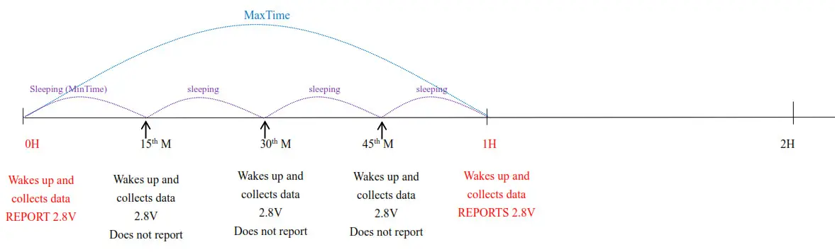
Note:
MaxTime=MinTime. Data will only be report according to MaxTime (MinTime) duration regardless BatteryVoltageChange value.
Example#2 based on MinTime = 15 Minutes, MaxTime= 1 Hour, Reportable Change i.e. BatteryVoltageChange= 0.1V.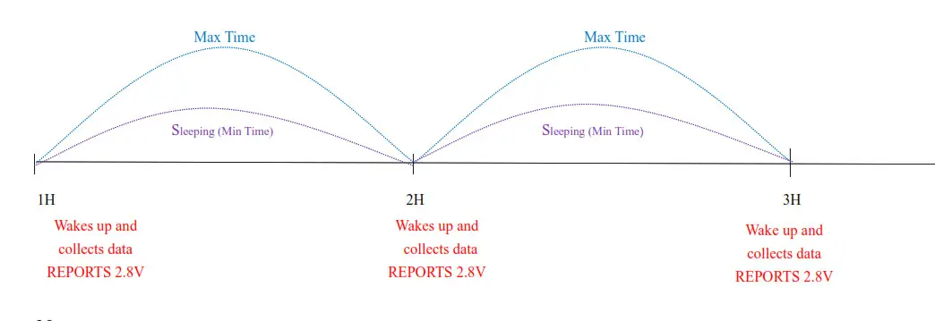
Example#3 based on MinTime = 15 Minutes, MaxTime= 1 Hour, Reportable Change i.e. BatteryVoltageChange= 0.1V.
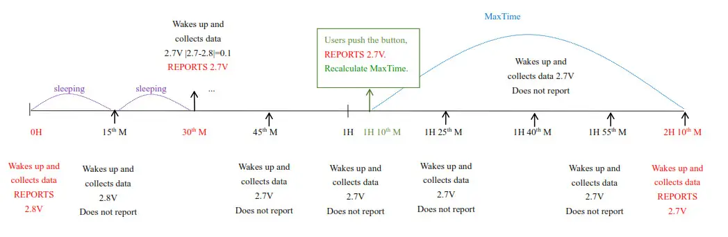
Notes:
- The device only wakes up and performs data sampling according to MinTime Interval. When it is sleeping, it does not collect data.
- The data collected is compared with the last data reported. If the data change value is greater than the ReportableChange value, the device reports according to MinTime interval. If the data variation is not greater than the last data reported, the device reports according to MaxTime interval.
- We do not recommend to set the MinTime Interval value too low. If the MinTime Interval is too low, the device wakes up frequently and the battery will be drained soon.
- Whenever the device sends a report, no matter resulting from data variation, button pushed or MaxTime interval, another cycle of MinTime / MaxTime calculation is started.
Important Maintenance Instruction
Kindly pay attention to the following in order to achieve the best maintenance of the product:
- Keep the device dry. Rain, moisture, or any liquid might contain minerals and thus corrode electronic circuits. If the device gets wet, please dry it completely.
- Do not use or store the device in dusty or dirty environment. It might damage its detachable parts and electronic components.
- Do not store the device under excessive heat condition. High temperature can shorten the life of electronic devices, destroy
batteries, and deform or melt some plastic parts. - Do not store the device in places that are too cold. Otherwise, when the temperature rises to normal temperature, moisture will form inside, which will destroy the board.
- Do not throw, knock or shake the device. Rough handling of equipment can destroy internal circuit boards and delicate structures.
- Do not clean the device with strong chemicals, detergents or strong detergents.
- Do not apply the device with paint. Smudges might block in the device and affect the operation.
- Do not throw the battery into the fire, or the battery will explode. Damaged batteries may also explode.
All of the above applies to your device, battery and accessories. If any device is not working properly, please take it to the nearest
authorized service facility for repair.
Documents / Resources
 |
netvox R311FD Wireless 3-axis Accelerometer Sensor [pdf] User Manual R311FD, Wireless 3-axis Accelerometer Sensor |