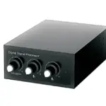
![]() NDS 260A Digital Signal Processor
NDS 260A Digital Signal Processor
User Manual

nakamichicaraudio.com ![]() nakamichi.global
nakamichi.global ![]() nakamichi.caraudio
nakamichi.caraudio
INTRODUCTION AND TROUBLESHOOTING
Thank you for your purchase and welcome to the world of Nakamichi! Please keep your original proof of purchase or invoice in a sate place in case of any warranty claims. Do also mail or register your warranty With the official Nakamichi service centers and/or agents to ensure that you are provided with the relevant technical support if required.
NOTICE
- To prevent short circuits, please keep the device away from water or damp places.
- If water or any other liquid enters the device, cut off the power immediately, and inform the nearest Nakamichi Service Center or Agent to inspect the product.
- Users are not recommended to disassemble the device as there are no user-serviceable parts inside, please contact the nearest Nakamichi Service Center if necessary.
TROUBLESHOOTING
Ensure all cables and parts are securely connected before turning on the power. Shown below is the basic troubleshooting procedure that you should follow.

Troubleshooting method:
| No. | Malfunction | Reason and Solution |
| 1 | No Power | • Check the power connection and make sure it’s secure. • Check the ACC connection and make sure it’s secure. |
| 2 | No Sound | • Double-check if the unit is in MUTE mode. • Check if you have chosen the correct input channel. |
| 3 | Unable to connect through USB | • Check the USB connection and make sure it’s secure. • Check if the driver” HID-compliant device ” has been properly installed in your PC. |
WHAT’S IN THE BOX
| NDSR260A | 1pc |
| User Manual | 20cs ( 1Chinese, 1English ) |
| USB2.0 Cable(l .5m) | 1pc |
| Mechanical flat head screws(PM3x6mm) | 8pc |
| Self-Tapping Oval Head Screws(PA4x20mm) | 4pc |
| Mounting brackets | 4pcs |
| Velcro(l 60x20mm) | 2Prs |
| 20P high-level input signal line(0.2m) | 1pc |
| 20p Speaker cable(0.2m) | 1pc |
| 16p Speaker power cable(0.2m) | 1pc |
| 25A FUSE | 2pcs |
PRODUCT TECHNICAL DATA
Product Data
| Dynamic Range(RCA Input) | 2>100d8 |
| S/N(RCA Input | 2>98dB |
| THD | <0.05% |
| Frequency Response | 20Hz–20KHz |
| Input Impedance | High Level: 51Q |
| Low-Level Output Impedance | 51Q2 |
| Signal Input Range | RCA: 7.5Vpp; High Level: 26Vpp |
| Signal Output Range | RCA: 7.5Vpp; Amplifier Power: 2CHx80W(Bridged lx200W)+6CHx50W |
| Working Temperature | -20- 70’C |
| Power | DC 9v-15V |
| REM lntput | High-Level Input Signal: H 1 +/H 1- or ACC control cable |
| REM Output | + 12V Startup Voltage Output(250mA) |
| Standby Power | <0.1W |
| Net Weight | Approx.2kg |
| Product Dimension | 213(L)xl 77(W)x49(H)mm |
Technical Sheet
| Input Type | 6 CH High Level, 2 CH Low Level, Built-in Bluetooth, U disk music, Optical |
| Output Type | 10 Channels Low Level, 2CHx80W(Bridged lx200W)+6CHx50W Power |
| Output Gain | Gain Range: Mute,-59.9dB-6dB |
| Output Signal EQ | 31-Band Equalizer Engine: 1. Frequency range: 20Hz-20KHz, 1 Hz Accuracy 2.Q value (slope): 0.404-28.852 3.Gain: -20.0dB- +20.0dB, 0.1 dB Accuracy |
| Output Signal Crossover |
Each output is equipped with multi-order high and low pass independent filters. 1. Filtering types: Link-Ril, Butter-W, Bessel 2. Filtering frequency division point: 20HZ-20KHz. Resolution 1 Hz 3. Filter slope (slope) setting: 6dB/ Oct to 48dB /Oct and OFF |
| Output Phase and Time Alignment |
Each output channel can be adjusted for phase and delay, parameter range: Phase: in-phase or reverse-phase (0/180) Delay: 0.000 to 20.000ms. 0 to 692 cm, 0 to 273 inch |
| Presets | 6 Presets into the device |
PRODUCT DIMENSIONS

INSTALLATION INSTRUCTIONS

THE SPEAKER WIRING IN NORMAL MODE

THE SPEAKER WIRING IN BRIDGE MODE

INTRODUCTION
The machine interface diagram is as follows:

- The controller port
Data calls and total volume adjustments can be performed by the line controller.

- Power indicator light/Protection indicator light
- Machine start mode switch
When the switch is turned to the “ACC” terminal, the machine is started by ACC, and when it is turned to the “HOST’ terminal, the machine is started by the high-level Hl+/Hl- input signal. - The fuse
Two 25A fuses. - High-level output and power port
7, 8 power amplifier output, can be bridged.

- High-level output port
1-6 power amplifier output.

- High-level input port
 a.”+” is positive or positive;”-” is negative or inverted (ground).
b. Before connecting the power supply, you must confirm that the power supply meets the designed power requirements and connect in strict accordance with the equipment instructions. Otherwise, the equipment may be damaged and may cause accidents such as fire, electric shock, etc. - USB2.0 Port, Connect to the computer tuning software
No need to download the driver installation, connected to the computer sound software is installed automatically. - Low-level output port
Connect up to l O channels low-level output. - Low-level input port
Connect up to 2 channels of low-level input. - Optical input port
When the optical input cable of the in-car CD or DVD player is connected, the sound source of the DSP is switched to digital input, and optical digital signals can be played. - USB port
Insert the USB flash drive and play the song in the USB flash drive under the player audio source.
SOFTWARE INTRODUCTION
PC Software Operation Introduction
(PC can be downloaded from the official website (http://www.nakamichicaraudio.com,CONTACT,downloads))
Computer Configuration Requirements: Screen resolution higher than 1280 x 768, otherwise the software UI is incomplete, only suitable for windows operation system laptop, desktops, and pads.

1. Menu edlttng area

Main functions: File, options operation.
a. Click the “File” pop-up window, and select to load the scene on your computer, save it as the scene on your computer, load the whole machine scene or save the whole machine scene.
Load machine preset scenarios
Save as machine preset scenarios
Load the scene file on your computer
Save it as a scene file on your computer
Loading machine scene
Save machine scene
Note: If you need to share tuning parameters, please connect the machine, and “save machine scene” to the personal computer to share this” machine scene”.
b. Click on “Option” to select Chinese and English switching, Noise Gate, RESET, InPuVOL, and About(A]
SOFTWARE INTRODUCTION
2. Function editing area

Main functions: scene. master source, mixer source, channel type, link, mixer and mode settings.
a. Scene: 6 sets of scene data con be recalled or stored.
b. Master source: Click the input audio source drop-down list to select the input audio source.
AUX, BT, HI Level, OPT, and USB.

c. Reset: Click Reset to clear the channel type or restore the default channel type.
d. link: Click the link to set the Link synchronization mode: copy from left to right or copy from right to left.
e. Click “Mixer” to enter the mixing interface, the interface is as shown below.

f. Click “Stereo” to switch between stereo or bridge.
3. Main volume and software connection editing area
![]()
SOFTWARE INTRODUCTION
Main functions: master volume and computer software connection settings.
a. Main volume adjustment range; off, -59.9-6dB. Click the speaker button to mute the volume.
b. Click the “Not Connected” button to connect the host with a PC.

4. Output channel type editing area

Main function: configure the type of output channel.
5. Channel delay, volume, phase editing area

a. Push the fader left or right to adjust the sound size. or enter a value or roll the mouse wheel in the volume input box to adjust the sound size. Click the speaker button to switch mute.
b. Positive phase adjustment: Click [0″] or [180°] to switch between the positive phase and reverse phase.
c. Delay: set the delay value by scrolling the mouse wheel in the delay input box, or enter the value to set the delay value.
d. Deloy Unit button: Click the drop-down list to select milliseconds, centimeters, and inches.
6. Channel divider editing area

Main Function Setup: Channel High & Low Pass Filter Setup.
Adjustable: Filter Type, Frequency point, and Q Value (Gradient or Slope).
SOFTWARE INTRODUCTION
7. Equalizer editing area

a. Reset EQ: It is used to restore the parameters of all equalizers to the original pass-through mode (the frequency of the equalizer, the Q value, and the gain are restored to the initial value].
b. Restore EQ: Switch between the currently designed equalizer state parameters and the pass-through mode (the gain of all equalization points is restored to 0 dB, the frequency and value are unchanged).
c. Click PEQ Mode to switch to GEQ Mode. The Q value and frequency cannot be adjusted in the PEQ Mode interface.
8. Channel EQ editing area

Main function configuration: Equilibrium design of current output channel, 31-band equalization adjustable: frequency, Q value (response bandwidth), and gain (increasing or decreasing the frequency response amplitude near the frequency point).
SOFTWARE INTRODUCTION(SMARTPHONE)
Smart-phone Software Operation Instruction
(APP can be downloaded from the official website(http://www.nakamichicaraudio.com,CONTACT,Downloads))

1. Home interface
It can restore factory settings, shore sound effects, save sound effects, turn on local sound effects, check the model and version number of the unit, and exit the software operation; volume, master source, storage, and recall of 6 sets of preset scenes.
A. Connection Status:
Red means not connected, and green means connected.
B. Menu:
You can restore factory settings, share sound effects, save sound effects, turn on local sound effects, view the model and version number of the machine, and exit the software operation.
C. Moster source:
Moster source: AUX/ Bluetooth / Hi.level / Optical/ USB to choose from.
D. Volume adjustment:
Press and hold the volume scale clockwise or counterclockwise to adjust the volume.
The main volume range is 0-66, The subwoofer range is 0-60, and The medium, high and low volume range is -20dB- +20dB.
E. Scene preset:
There are I6 presets to choose from.
F. Advanced settings:
Click (Advanced Settings] to enter the settings of the delay interface, channel interface, EQ interface, and mixing.
2. Deloy interface
Sound field positioning output delay adjustment.
G. Unit switching:
Switch between milliseconds, centimeters, and inches.
H. Delay setting:
Click the setting window of the corresponding channel. Slide the dots left and right to set the delay value. Delay settings can be made for CHL- CHl0 speakers.
Deloy range: millisecond range: 0.000- 20.000; cm range: 0-692; inch range: 0-273.
3. Channel interface
Channel high-low-pass crossover setting with high-low-pass independent filtering.
SOFTWARE INTRODUCTION(SMARTPHONE)

Adjustable: Filter type, frequency, and Q value (slope or slope).
I. Output channel selection:
Twelve channels are available.
J. Output channel volume setting:
You can adjust the volume by sliding left and right. The volume range is 0-60. Click the speaker button to mute. Configurable output channel type, forward and reverse switching.
K. Channel divider selection:
Channel type: Choose from Link-Rill, Butter-W, and Bessel.
Frequency Range: 20HZ~20KHz.
Slope selection:
6dB/Oct, 128/Oct, 18d8/Oct, 24dB/Oct, 308/Oct, 36dB/Oct, 428/Oct,48dB/Oct, and OFF can be selected.
L. Joint tuning and channel type settings:
Click [Reset] to reset the output channel type so that the output type can be customized.
Click [Stereo] to switch between stereo mode and bridge mode.
Click[link] the joint debugging window will pop up, and select the joint debugging method.
4. EQ interface
Corresponding to the adjustment of the output channel EQ curve (gain, Q value, and frequency): reset equalization, pass-through equalization, or parametric equalization operation settings.
M. EQ display:
Edit the display area.
N. Output EQ gain, Q value, and frequency settings:
Output EQ gain setting: A total of 31 EQ. left and right sliding screens can select EQ, you can drag the slider up and down. Select the first line value, and drag the slider bar left and right in the pop-up dialog box to adjust the adjustment range: -20d8 – +20d8.
Q value: Click the second line value, and drag the slider bar left and right in the pop-up dialog box to adjust, the adjustment range is 0.404 – 28.852.
Frequency setting: Click the third line value, and drag the slider bar left and right in the pop-up dialog box to adjust it.
The adjustment range is 20Hz – 20KHz.
SOFTWARE INTRODUCTION(SMARTPHONE)
0. Reset equalization, restore equalization, and pass-through equalization settings:
Click [Reset EQ] to restore the parameters of the 31-band equalizer to the original pass-through mode (the equalizer frequency, Q value, and gain are restored to their initial values). When there is channel adjustment, display [straight-through equalization], click [straight- through equalization], click [OK], all values (frequency, Q value and gain) will return to the initial value. At this time, the [straight-through equalization] button will become [recovery equalization]. Press the button and click [Resume Equilibrium], all values
(frequency, Q value, and gain) will be restored to the value before the pass-through.
Click [P. EQ Mode], click [OK] to switch to Graphic Equalization, and click [G.EQ Mode], click [OK] to switch to Parametric Equalization.
5. Mixing interface
Five sound source modes can be selected. It includes the mixing selection and adjustment of 6 groups of high-level, Bluetooth left and right channels, optical fiber left and right channels, and aux left and right channels. The adjustment range is 0-100.
 http://www.nakamichicaraudio.com
CONNECT WITH US ONLINE TO EXPLORE NAKAMICHl’S COMPLETE RANGE,
INSTRUCTIONS & SOFTWARE DOWNLOADS AND WARRANTY REGISTRATION.
WWW.NAKAMICHICARAUDIO.COM
nakamichi.global nakamichi.caraudio
Nakamichi Corp, Japan Made in China ]
Documents / Resources
 |
Nakamichi NDS 260A Digital Signal Processor [pdf] User Manual NDS 260A, Digital Signal Processor, Signal Processor, Digital Processor, NDS 260A, Processor |