![]() VOXI LEL
VOXI LEL
MP82X Series
Quick Start Guide
Read Before Operating
The VOXI LEL User’s Guide must be carefully read by all individuals who have or will have the responsibility of using, maintaining or servicing this product. The product will perform as designed only if it is used, maintained and serviced in accordance with the manufacturer’s instructions.
![]() Warnings
Warnings
- Never operate the monitor when the cover is removed.
- Remove the monitor cover only in a non-hazardous area.
- Use only mPower’s sensor and accessories. Substitution of components will impair intrinsic safety and void warranty.
- For optimal results, it is recommended to allow the unit to warm up for 2 minutes after entering the test interface.
- For maximum safety, the accuracy of the instrument should be checked by exposing it to a known concentration calibration gas at regular intervals.
- Ensure that the gas inlet is not blocked.
- Ensure that all filters are clean and replaced on a regular basis.
- Remove the sensor only if necessary for repair. Zero and span calibration are required once the sensor is moved.
Mounting
Mount the VOXI LEL to a wall or pole using the bracket and pole loops provided.

User Interface
The user interface of the VOXI LEL has an LCD graphic display and LED indications. The operations are controlled using an IR remote programmer.

*The ground wire must be connected to the VOXI housing reliably. We recommend using AWG11 as ground wire.
Wiring Diagram

| 1 | 2 | 3 | 4 | 5 | 6 | 7 | 8 | 9 |
| Low Alarm Contacts | High Alarm Contacts | Fault Alarm Contacts | ||||||
| Norm. Open |
Com | Norm. Closed |
Norm. Open |
Com | Norm. Closed |
Norm. Open |
Com | Norm. Closed |
| 10 | 11 | 12 | 13 | 14 |
| RS485B | RS485A | 4-20 mA | +V (10-30V, <1W) |
| 15 | 16 | 17 | 18 | 19 |
| +V | -V | Strobe/Horn Fault Alarm (reserved) |
Strobe/Horn Low Alarm (reserved) |
Strobe/Horn High Alarm (reserved) |
Start Up
After supplying 10-30V power to the VOXI LEL, it enters the self-test process, displaying the sensor range, high/low alarms, span value and the LEDs are tested. When the startup is complete, the LEL readings are displayed. Sampling is by diffusion. If any alarm level is exceeded, the Alarm LED flashes and the display backlight changes color.

Infrared Remote Programmer
The Remote Programmer uses a CR2025 3V battery and communicates with the transmitter from up to 3 m (10 ft). when directed straight at the transmitter display (instead of from an angle).

Programming Interface
The VOXI EC switches to a programming display when initiated by the infrared Remote Programmer.
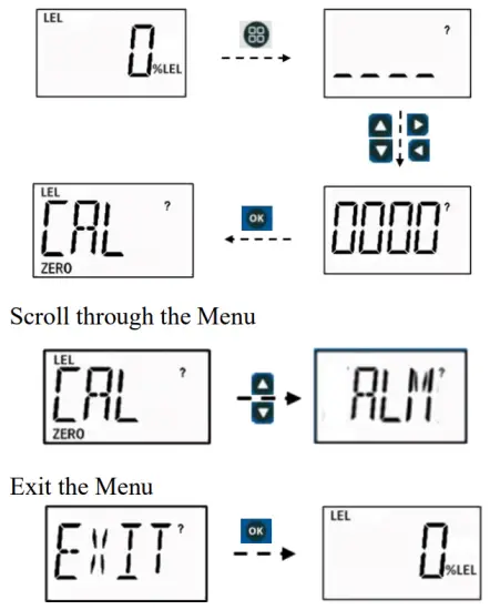
- Enter Menu
Press the Menu Access key and enter the password.
Use the up/down keys to increase or decrease numbers and left/right keys to move the cursor. After entering the last digit move the cursor to the “?” and press OK to enter the menu. - Basic vs Advanced Menus
The default Basic password (“0000”) gives access to the most common functions such as zero calibration, span calibration, calibration gas concentration setting, and high/low alarm settings. For more advanced features including correction factor, site ID, baud rate, 4-20 mA adjustment, etc. enter the Advanced password given in the full User Manual. - Enter Selection
Use the up/down keys to scroll through the menu, and the OK key to select the item. - Exit
To exit a sub-menu, press Cancel . To exit the Main Menu, scroll to the “EXIT” menu and press OK to return to the reading display.
Enter the main menu, then enter the password
Zero Calibration
Zero calibration must be done with clean air. If the ambient air is suspected of having a background of detectable chemical, use pure air or nitrogen from a cylinder to ensure a proper zero. To apply gas, attach the calibration adapter, as shown to the right. If no calibration adapter is available, the rain cap can be used as an alternative.
- Enter the main menu, scroll to CAL ZERO, apply zero gas if needed and press OK to start the zero calibration.
- Alternatively, press the short-cut “Zero” button on the programmer front panel to go directly to zero calibration.
- A 15-second countdown is initiated, after which Pass or Fail is displayed.

- To abort, press .
Span Calibration
- Enter the main menu, scroll to CAL SET to check that the span is set to the same value as the gas cylinder.
- Connect the calibration gas, start the gas flow (0.5 LPM preferred), scroll to CAL SPAN and press OK.
- Or, press the “Span” button on the programmer front panel to go directly to span calibration.

- A countdown timer is started with length depending on sensor type, after which Pass or Fail is displayed.
- To abort, press .
Span Gas Setting
Enter the main menu, scroll to CAL SET, and press OK.
Adjust the span gas concentration using the up & down keys and move the cursor using the left & right keys. Move the cursor to the “?” and press OK to save.
Sensor Replacement
- Open the housing and disconnect the sensor cable plug.
- Remove the rain cap and unscrew the LEL sensor module.
- Insert a new sensor and reassemble in reverse order.

mPower Electronics Inc.
2910 Scott Blvd. Santa Clara, CA 95054
www.mpowerinc.com
info@mpowerinc.com
PN: M026-4002-000
Documents / Resources
 |
mPower Electronics VOXI LEL MP82X Series Combustible Gas Transmitters [pdf] User Guide MP82X, VOXI LEL MP82X Series Combustible Gas Transmitters, VOXI LEL MP82X Series, Combustible Gas Transmitters, Gas Transmitters, Transmitters |


