MODINE 5-587.8 Remote Monitoring Panel Instruction Manual

Remote Monitoring Panel¹

¹Example panel shown. Actual panel may be configured differently.
![]() WARNING
WARNING
- Disconnect power supply before making wiring connections or working on this equipment. Follow all applicable safety procedures to prevent accidentals power up. Failure to do so can result in injury or death from electrical shock or moving parts and may cause equipment damage.
- All appliances must be wired strictly in accordance with wiring diagram furnished with the unit. Any wiring different from the wiring diagram could result in a hazard to persons and property.
- All wiring must be done with a wiring material having a temperature rating of at least 105°C.
IMPORTANT
- The use of this manual is specifically intended for a qualified installation and service agency. All installation and service of these kits must be performed by a qualified installation and service agency.
- These instructions must be used in conjunction with the Installation and Service Manual originally shipped with the appliance being converted, in addition to any other accompanying component supplier literature.
Model Application
The purpose of the remote monitoring panel is to offer control and/or indication of the current operating conditions of a heating/make-up air unit, model series “D”, “H”, “I”, or “O”.
Remote Panel Components
The standard panel includes two lights (“Heat On” and “Blower On”). Other panels are available with the following options:
- Indicator Light Tags (panel holds two to five lights):
Heat On
Cool On
Blower On
Dirty Filters
Power On
- Switch Tags (panel holds one to two switches):
2-Position Switches
Day/Night
Occupied/Unoccupied
On/Off
Heat/Off
High/Low
Summer/Winter
Heat/Cool
Auto/Off - Other Devices Available:
Maxitrol Electronic Set Point Adjuster – TD121
Component Data:
- Lights:
Red, 24VAC, 60Hz, 1 Watt - Switches:
DPDT (2 position) or DPDT-Center Off (3 position) - Thermostats:
– None
– Modulating Discharge Air Set Point Adjuster
Installation
The remote monitoring panel is to be mounted indoors in an environment free of excessive contaminants such as oil, moisture, and dirt. Mounting holes are provided in the rear of the enclosure for mounting to a wall, terminal box, etc. Conduit entrance knockouts are provided on the sides, bottom, and rear of the enclosure.
Modine Manufacturing Company has a continuous product improvement program, and therefore reserves the right to change design and specifications without notice.
INSTALLATION – REMOTE MONITORING PANEL
Wiring
Installation of wiring must conform with local building codes, or in the absence of local codes, of the National Electric Code ANSI/ NFPA 70 – Latest Edition. Unit must be electrically grounded in conformance to this code. In Canada, wiring must comply with CSA C22.1, Part 1, Electrical Code.
The remote monitoring panel components are designed to accept the following connections:
- Lights:
3/16″ quick connect terminals - Switches:
1/4″ quick connect terminals - Maxitrol TD121 Set-Point Adjuster:
1/4″ quick connect terminals
Wiring Diagram Selection
- For system units (factory supplied blower), refer to the job specific unit wiring diagram provided with the unit.
- For deviations to these wiring diagrams or the job specific wiring diagrams, consult the factory.
Remote Panel Dimensions
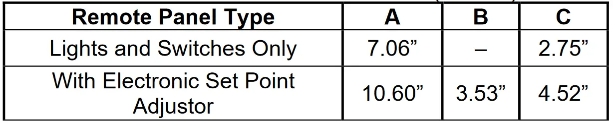
Figure 2.1 – Remote Panel Dimensions (inches)

Table 2.1 – Remote Panel Dimensions (inches)
Modine Manufacturing Company has a continuous product improvement program, it reserves the right to change design and specifications without notice.
© Modine Manufacturing Company 2024
Documents / Resources
 |
MODINE 5-587.8 Remote Monitoring Panel [pdf] Instruction Manual 5-587.8 Remote Monitoring Panel, 5-587.8, Remote Monitoring Panel, Monitoring Panel, Panel |