mmt FU8002-915 Radio Communication Module
BRIEF DESCRIPTION
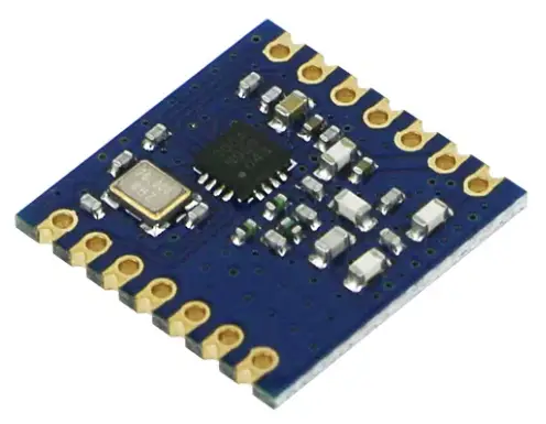
Radio communication module FU8002-915 is designed to built-in to medical devices for wireless connection of computers with installed UDMvision software like a part of medical devices from the family of Urodynamics 3rd generation medical devices manufactured by MEDKONSULT medical technology s.r.o., Pasteurova 67/15, 779 00 OLOMOUC, Czech Republic.
The product is not separately saleable and is intended solely for the manufacturer’s own use in the manufacture of medical devices, or authorized service of medical devices. The product is not a self-contained radio device.
The connector is within the device enclosure and can only be accessed by disassembly of the device that is not normally required.
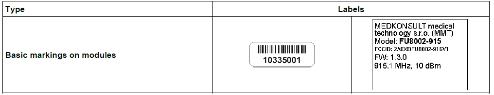
Identification
FCC ID 2A8XBFU8002-915V1
Marking
GENERAL REQUIREMENTS
Installation of the FU8002-915 radio module should only be performed by qualified personnel following detailed guidelines provided in this manual to ensure FCC compliance. Any modification to the module or its antenna could lead to the device operating outside of FCC-approved conditions, potentially necessitating a new authorization.
Installation and servicing of the Radio communication module FU8002-915 is only carried out by the manufacturer or an authorized service center. Installation must be controlled and requires special training.
This module is not a stand-alone product and can be commissioned by an authorized medical device service for urodynamic systems of the manufacturer MEDKONSULT Medical Technology s.r.o. Please contact your distributor for this purpose.
INTEGRATION INSTRUCTIONS (ACCORDING TO KDB996369 D03 2.0)
- Chapter 2.2
The FU8002-915 has been granted Federal Communications Commission (FCC) CFR47 Telecommunications, Part 15 Subpart C “Intentional Radiators” under sections 15.247, along with modular approval pursuant to Part 15.212 Modular Transmitter approval guidelines. - Chapter 2.3
The antenna must not be changed for a different type than specified in the technical parameters stated in the FU8002-915 Datasheet. Replacement may only be carried out by an authorized service of the manufacturer. The antenna should be installed so that the end user cannot change or modify the antenna.
The radio parameters cannot be changed and are hard-coded in the module.
The operational communication of the Radio communication module FU8002-915 is fully controlled by the control software for UDMvision of the urodynamic systems. The communication protocol is proprietary and is used for intercommunication only for the MMT family of Urodynamics 3rd generation medical devices. - Chapter 2.4
Not applicable - Chapter 2.5
Trace antenna designs: Not applicable.
The antenna must not be changed for a different type than specified in the technical parameters.
Any deviation(s) from the defined parameters of the antenna of the stated type require that the host product manufacturer must notify the module grantee that they wish to change the antenna type or parameters.
In this case, a Class II permissive change application is required to be filed by the grantee, or the host manufacturer can take responsibility through the change in FCC ID (new application) procedure followed by a Class II permissive change application. - Chapter 2.6
To ensure compliance with FCC RF exposure regulations, the FU8002-915 radio module must maintain a minimum separation distance of 20 cm from all persons during operation and must not be co-located or operated in conjunction with any other antenna or transmitter except in accordance with FCC multi-transmitter product procedures. This module has been designed to operate with specific antennas. Using unauthorized antennas, modifying the antenna design, or operating the module outside the specified conditions may violate FCC regulations and void the user’s authority to operate the equipment.
If the FU8002-915 radio module is used in a portable application (antenna is less than 20 cm from persons during operation), the integrator is responsible for performing Specific Absorption Rate (SAR) testing in accordance with FCC rules 2.1091. For more information, please refer to the in KDB 996369 D03 OEM Manual v01 and KDB 996369 D04 Module Integration Guide v02.
The end user manual shall be provide additional text from the host product manufacturer to end users, It shall include FCC compliance statements related to the transmitter or labeling requirements. If RF exposure statements and use conditions are not provided, then the host product manufacturer is required to take responsibility of the module through a change in FCC ID (new application). - Chapter 2.7
The antenna must not be changed for a different type than specified in the technical parameters stated in the FU8002-915 Datasheet. Replacement may only be carried out by an authorized service of the manufacturer. The antenna should be installed so that the end user cannot change or modify the antenna. - Chapter 2.8
The FU8002-915 module has been labeled with its own FCC ID number, and if the FCC ID is not visible when the module is installed inside another device, then the outside of the finished product into which the module is installed must also display a label referring to the enclosed module. This exterior label can use wording as following:
Contains Transmitter Module FCC ID: 2A8XBFU8002-915V1
-or
Contains FCC ID: 2A8XBFU8002-915V1 - Chapter 2.9
Testing of the host product with all the transmitters installed – referred to as the composite investigation test- is recommended, to verify that the host product meets all the applicable FCC rules. The radio spectrum is to be investigated with all the transmitters in the final host product functioning to determine that no emissions exceed the highest limit permitted for any one individual transmitter as required by Section 2.947(f). The host manufacturer is responsible to ensure that when their product operates as intended it does not have any emissions present that are out of compliance that were not present when the transmitters were tested individually.
If the modular transmitter has been fully tested by the module grantee on the required number of channels, modulation types, and modes, it should not be necessary for the host installer to re-test all the available transmitter modes or set-tings. It is recommended that the host product manufacturer, installing the modular transmitter, perform some investigative measurements to confirm that the resulting composite system does not exceed the spurious emissions limits or band edge limits (e.g., where a different antenna may be causing additional emissions).
The testing should check for emissions that may occur due to the intermixing of emissions with the other transmitters, digital circuitry, or due to physical properties of the host product (enclosure). This investigation is especially important when integrating multiple modular transmitters where the certification is based on testing each of them in a stand-alone configuration.
Chapter 2.10
The host product manufacturer should perform the test of radiated & conducted emission and spurious emission etc. according to FCC Part 15C: 15.247 and 15.209 & 15.207, 15B class B requirement, only if the test result complies with FCC part 15C: 15.247 and 15.209 & 15.207, 15B class B requirement.
As the module is intended for use in medical devices, it is necessary to perform EMC tests on the complete instrument including the module in accordance with IEC EN 60601-1-2.
The host product manufacturer is strongly recommended to confirm compliance with FCC requirements for the transmitter when the module is installed in the host.
The host product manufacturer is responsible for compliance to any other FCC rules that apply to the host not covered by the modular transmitter grant of certification. If the grantee markets their product as being Part 15 Subpart B compliant (when it also contains unintentional radiator digital circuity), then the grantee shall provide a notice stating that the final host product still requires Part 15 Subpart B compliance testing with the modular transmitter installed.
TESTPLAN – TESTING REQUIREMENTS AND METHODOLOGY
Overview of Testing Methodology
This module does not contain a shield and does not have buffered modulation/data inputs and therefore is limited. The host integrator will be required to file a Class II Permissive Change for each host-specific installation. The following testing should be performed to demonstrate continued compliance.
The following testing methodology ensures compliance with regulatory requirements and verifies the correct functionality of the module within host devices by MEDKONSULT medical technology s.r.o..
Testing includes:
- Measurement of radiated unwanted emissions (15.209(a))
- Testing of band edge frequencies (15.247(d))
- Measurement of emissions in idle mode (15.109(a))
- Compatibility testing with urodynamic systems (4.2.4)
- Verification of buffered data transmission handling (4.2.5)
- EMC and EMI compatibility testing (4.2.6)
Test Scenarios and Measurement Methodology
Measurement of Radiated Emissions (FCC 15.209(a))
Test Objective:
Verify that emissions from the FU8002-915 module in the range of 30 MHz – 9.2 GHz do not exceed permitted limits.
Procedure:
- The FU8002-915 module is installed in the test environment according to the installation manual.
- A spectrum analyzer is used to measure emissions at harmonic frequencies.
- The results are compared with FCC Part 15.209(a) limits.
Acceptance Criteria: Emissions must not exceed the FCC-defined threshold values.
Testing of Band Edge Frequencies (FCC 15.247(d))
Test Objective:
Ensure that the module does not exceed emission limits at the edge frequencies of its operating band (902–928 MHz).
Procedure:
- The module is tested at a 915.1 MHz frequency in full operational mode.
- The spectral power density at band edges is measured.
- Results are compared against FCC requirements.
Acceptance Criteria:
Emissions outside the operating band must meet the limits set by FCC 15.247(d).
Measurement of Emissions in Idle Mode (FCC 15.109(a)
Test Objective:
Verify that the module does not create interference in idle mode beyond defined limits.
Procedure:
- The module is placed in receive or idle mode.
- Emissions in the range of 30 MHz – 5 GHz are measured.
- Results are compared with FCC Part 15.109(a) limits.
Acceptance Criteria:
Emissions must be below the thresholds set by FCC 15.109(a).
Compatibility Testing with the Host Device
Test Objective:
Ensure that the module functions correctly within the urodynamic system without causing unwanted interference.
Procedure:
- The module is integrated into the test urodynamic system.
- Common operational scenarios, including data transmission, are simulated.
- Transmission errors, system response, and potential interference effects are mon
Acceptance Criteria:
The module must not disrupt the normal operation of the host device.
Verification of Buffered Data Transmission Handling
Test Objective:
Assess how the module handles data buffering limitations during communication and ensure that any data buffering mechanism does not result in non-compliance with FCC transmission rules.
FCC Compliance Relevance:
- FCC Part 15 regulations require that transmission characteristics (such as duty cycle, burst duration, and occupied bandwidth) remain within permitted limits.
- Data buffering mechanisms must not introduce unintended continuous or prolonged transmissions that could violate these rules.
Procedure:
- The module is configured for continuous and intermittent data transmission scenarios to observe any impact on emission charactristics.
- Spectrum measurements are taken before, during, and after buffer-induced transmissions to detect any deviations in duty cycle, emission bandwidth, or transmission power levels.
- Transmission logs are analyzed for instances where buffering might cause extended transmission durations or spurious emissions.
Acceptance Criteria:
Transmission characteristics must remain within FCC-approved limits, including power levels, duty cycle, and spurious emission thresholds.
No unintended continuous transmission should occur as a result of buffering mechanisms.
Emissions during buffered transmissions must remain within regulatory spectral limits.
Test Objective:
Assess how the module handles data buffering limitations during communication.
Procedure:
- The module is configured for continuous data transmission scenarios.
- Transmission logs are analyzed for dropped packets, delays, and system performance.
- Any inconsistencies in data buffering behavior are documented and tested for potential optimizations.
Acceptance Criteria:
Data buffering should not introduce significant latency or data loss beyond defined thresholds.
EMC and EMI Compatibility Testing
Test Objective:
Ensure the module does not introduce electromagnetic interference and is resistant to external EMI.
Procedure:
- The module is tested for EMC compliance under IEC 60601-1-2 conditions.
- Measurements of susceptibility to external RF fields are performed.
- Interference effects on other components in the host device are analyzed.
Acceptance Criteria:
- The module must comply with IEC 60601-1-2 for EMC.
- No significant degradation in performance due to EMI.
Testing Equipment
| Item | Usage |
| Spectrum analyzer | Measurement of emissions |
| Shielded communication environment | Interference testing |
| Urodynamic device | Compatibility testing |
| Data transmission monitor | Buffered data handling assessment |
| EMI/EMC test chamber | Compliance with IEC 60601-1-2 |
Environmental Conditions
- Temperature: 20–25°C
- Humidity: 30–60%
- Test Chamber Type: Semi-anechoic chamber (for EMI/EMC tests)
Summary of Testing Requirements
This chapter ensures compliance with the test plan and defines a clear testing methodology to meet FCC requirements. Test results must be documented and archived for certification purposes.
Regulatory Compliance Notes
Class II Permissive Change: If the module is integrated into a new host system, the integrator must file a Class II Permissive Change with the FCC.
Integration Guidance: The host device manufacturer is responsible for ensuring continued compliance with FCC regulations
FAQ
- Can the antenna be changed?
No, the antenna specified in the technical parameters should not be changed. Any modifications require notification to the module grantee. - Who should perform the installation of the radio module?
Installation should only be done by qualified personnel or authorized service centers to ensure compliance and proper functioning.
Documents / Resources
 |
mmt FU8002-915 Radio Communication Module [pdf] User Guide FU8002-915, FU8002-915 Radio Communication Module, Radio Communication Module, Communication Module, Module |


