![]()
DATASHEET
MCRN2 RFID Reader/Writer Module

MCRN2 R 2.0
Aug. 01, 2024
Key Features
| Frequency | 13.56 MHz |
| Interfaces | RS232/RS485, USB |
| Standards | ISO14443A/B, ISO15693 |
| Supported Cards & Transponders | MIFARE® DESFire/Plus MIFARE® Classic/Ultralight NTAG I-Code |
| Antennas | Internal or external |
| Power supply | +7V to +60V DC or USB Bus |
DESCRIPTION
The MCRN2 RFID reader is a versatile and reliable device, designed for applications requiring serial and USB interfaces. It supports baud rates of up to 230k, ensuring fast and efficient communication. The reader operates within a wide voltage range and can be integrated into +12V or +24V systems, making it suitable for various industrial environments. Its robust design and flexible connectivity options make the MCRN2 an ideal choice for both simple and complex RFID systems. The powerful internal antenna can read cards/tags up to 80mm away, and the USB interface can optionally run in Keyboard Emulation mode.
ELECTRICAL
| SYMBOL | PARAMETER | MIN | TYP | MAX | UNIT |
| VIN | Input Voltage | +7 | +12 | +60 | V |
| IIN | Input Current (VIN=+12V) | – | 100 | 200 | mA |
| VR | Maximum Reverse Voltage | – | +58 | – | V |
| TA | Ambient Temperature Range | -30 | – | +85 | °C |
| VTVS | TVS Clamping Voltage | – | +64 | – | V |
| RS485-VOD | Differential Output (RL=54Ω) | +1.5 | +2 | +3.3 | V |
| RS485-A/B | Input Voltages | -8V | – | +13 | V |
| RS485-A/B | Output Voltages | – | +3.3 | – | V |
| RS232 Receiver | Input Voltages | -30 | +30 | V | |
| RS232 Transmitter | Output Voltages | ±5 | ±5.2 | – | V |
| ESD Performance | |||||
| RS485-A/B | IEC 61000-4-2 (ESD) ±15kV (air), ±8kV (contact) | ||||
| RS232 | IEC 61000-4-2 (ESD) ±15kV (air), ±8kV (contact) | ||||
| USB | ESD Protection for 2 high-speed I/O channels and VDD IEC 61000-4-2 (ESD) ±15kV (air), ±8kV (contact) IEC 61000-4-4 (EFT) 40A (5/50ns), IEC 61000-4-5 (Lightning) 12A (8/20μs) |
||||
| MTBF | 500.000h | ||||
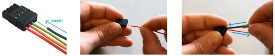
CONNECTOR PINOUT

| Main Connector | RS232 Mode | RS485 Mode |
| 1 | GND – Ground | GND – Ground |
| 2 | RX Input | B |
| 3 | TX Output | A |
| 4 | +VIN (+7 to +60 VDC) | +VIN (+7 to +60 VDC) |
| IO Connector | LED Mode | Output Mode | IIC Mode |
| 1 | +5VDC | +5VDC | +5VDC |
| 2 | LED1 cathode input | Output1 | SCL – Clock |
| 3 | LED2 cathode input | Output2 | SDA – Data |
| 4 | GND – Ground | GND | GND |
Fast and easy connection
FEATURES

- RS232/485 up to 230K Baud
- USB 2.0 in HID or Keyboard Emulation mode
- Optional MDB-Interface
- Tricolor RGB LED indicator
- Full NFC support
- Integrated or external antenna
- 2 x GPIOs and Buzzer
- Bootloader for firmware update
- Power over USB
- +7V to +60V DC power supply (optional +5V version)
- 100mA @ +12V current consumption
- -30 to +85 ºC ambient Temperature
RELAY-BOARD
A relay board with 2x solid-state relays is available. The relays are 1.2A (3A peak) and 30V.

DIMENSIONS
59 x 71.5 x 9.10 mm

ORDERING CODES
| ARTICLE NR: | RS485 | RS232 | USB | Wi-Fi/BLE | Int. ANT | MDB | Relay-Board |
| MCRN2-1110 | X | X | * opt. | X | * opt. | ||
| MCRN2-1100 | X | X | * opt. | X | * opt. | ||
| MCRN2-W100 | X | X | X | X | * opt. | ||
| MCRN2-MDB | X | X | * opt. | X | X |
FCC Regulatory Conformance
Radiation Exposure Statement
This equipment complies with FCC radiation exposure limits set forth for an uncontrolled environment. This equipment should be installed and operated at a minimum distance of 20cm between the radiator and your body.
NOTE: This equipment has been tested and found to comply with the limits for a Class A digital device, pursuant to part 15 of the FCC Rules. These limits are designed to provide reasonable protection against harmful interference in a residential installation.
This equipment generates uses and can radiate radio frequency energy and, if not installed and used in accordance with the instructions, may cause harmful interference to radio communications. However, there is no guarantee that interference will not occur in a particular installation. If this equipment does cause harmful interference to radio or television reception, which can be determined by turning the equipment off and on, the user is encouraged to try to correct the interference by one or more of the following measures:
- Reorient or relocate the receiving antenna.
- Increase the separation between the equipment and receiver.
- Connect the equipment into an outlet on a circuit different from that to which the receiver is connected.
- Consult the dealer or an experienced radio/TV technician for help.
FCC Part 15.19 Warning Statement- (Required for all Part 15 devices)
THIS DEVICE COMPLIES WITH PART 15 OF THE FCC RULES. OPERATION IS SUBJECT TO THE FOLLOWING TWO CONDITIONS: (1) THIS DEVICE MAY NOT CAUSE HARMFUL INTERFERENCE, AND (2) THIS DEVICE MUST ACCEPT ANY INTERFERENCE RECEIVED, INCLUDING INTERFERENCE THAT MAY CAUSE UNDESIRED OPERATION.
FCC Part 15.21 Warning Statement-
NOTE: THE GRANTEE IS NOT RESPONSIBLE FOR ANY CHANGES OR MODIFICATIONS NOT EXPRESSLY APPROVED BY THE PARTY RESPONSIBLE FOR COMPLIANCE. SUCH MODIFICATIONS COULD VOID THE USER’S AUTHORITY TO OPERATE THE EQUIPMENT.
![]()
Minova Technology GmbH
Lindenstraße 2
D-78628 Rottweil
www.minovatech.de

Documents / Resources
 |
minova MCRN2 RFID Reader Writer Module [pdf] Owner's Manual MCRN2, MCRN2 RFID Reader Writer Module, RFID Reader Writer Module, Reader Writer Module, Writer Module, Module |