![]()
![]() lcs+340/F/A Ultrasonic Proximity Switch with One Switching Output And IO-Link
lcs+340/F/A Ultrasonic Proximity Switch with One Switching Output And IO-Link
User Manual  Operating manual
Ultrasonic proximity switch with one switching output and IO-Link
lcs+340/F/A
lcs+600/F/A
Product Description
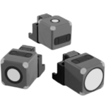
The lcs+ sensor offers a non-contact measurement of the distance to an object which must be positioned within the sensor’s detection zone.
The switching output is set conditional upon the adjusted detect distance. Via the Teach-in procedure, the detect distance and operating mode can be adjusted. One LED indicates operation and the state of the switching output.
The lcs+ sensors are IO-Link-capable in accordance with IO-Link specification V1.1 and support Smart Sensor Profile like Digital Measuring Sensor.
Safety Notes
- Read the operating manual prior to start-up.
- Connection, installation and adjustments may only be carried out by qualified staff.
- No safety component in accordance with the EU Machine Directive, use in the area of personal and machine protection not permitted.
Proper Use
lcs+ ultrasonic sensors are used for non-contact detection of objects.
 |
 |
colour |
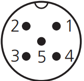
| 1 | +UB | brown |
| 3 | –UB | blue |
| 4 | F | black |
| 2 | – | white |
| 5 | Sync/Com | grey |
Fig. 1: Pin assignment with view onto sensor plug and colour coding of the microsonic connection cables
Installation
- Mount the sensor at the place of fitting.
- Connect a connection cable to the M12 device plug, see Fig. 1.
Start-up
- Connect the power supply.
- Set the parameters of the sensor, see Diagram 1.
Factory setting
- Switching output on NOC
- Detect distance at operating range
Operating Modes
Three operating modes are available for the switching output:
- Operation with one switching point
The switching output is set when the object falls below the set switching point. - Window mode
The switching output is set when the object is within the window limits. - Two-way reflective barrier
The switching output is set when the object is between sensor and fixed reflector.
| lcs+340… | ≥2.00 m | ≥18.00 m |
| lcs+600… | ≥4.00 m | ≥30.00 m |
Fig. 2: Minimal assembly distances without synchronisation
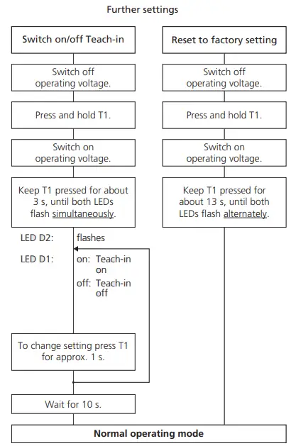
Diagram 1: Set sensor parameters via Teach-in procedure

Synchronisation
If the assembly distance of multiple sensors falls below the values shown in Fig. 2, the internal synchronisation should be used. For this purpose set the switching outputs of all sensors in accordance with Diagram 1. Finally interconnect each pin 5 of the sensors to be synchronised.
Maintenance
microsonic sensors are maintenancefree. In case of excess caked-on dirt we recommend to clean the white sensor surface.
Notes
- The sensors of the lcs+ family have a blind zone, within which a distance measurement is not possible.
- The lcs+ sensors are equipped with an internal temperature compensation. Due to the sensors self heating, the temperature compensation reaches its optimum workingpoint after approx. 30 minutes of operation.
- In the normal operating mode, an illuminated yellow LED signals that the switching output is switched through.
- The lcs+ sensors have a push-pull switching output.
- In the »Two-way reflective barrier« operating mode, the object has to be within the range of 0-85 % of the set distance.
- In the »Set detect point – method A« Teach-in procedure the actual distance to the object is taught to the sensor as the detect point. If the object moves towards the sensor (e.g. with level control) then the taught distance is the level at which the sensor has to switch the output.
- If the object to be scanned moves into the detection area from the side, the »Set detect point +8 % – method B« Teach-in procedure should be used. In this way the switching distance is set 8 % further than the actual measured distance to the object. This ensures a reliable switching distance even if the height of the objects varies slightly.
Technical data
 |
 |
 |
| blind zone | 0 to 350 mm | 0 to 600 mm |
| operating range | 3,400 mm | 6,000 mm |
| maximum range | 5,000 mm | 8,000 mm |
| angle of beam spread | see detection zones | see detection zones |
| transducer frequency | 120 kHz | 80 kHz |
| resolution | 0.18 mm | 0.18 mm |
| reproducibility | ±0.15 % | ±0.15 % |
| detection zones for different objects: The dark grey areas represent the zone where it is easy to recognise the normal reflector (round bar). This indicates the typical operating range of the sensors. The light grey areas represent the zone where a very large reflector–for instance a plate – can still be recognised. The requirement here is for an optimum alignment to the sensor. It is not possible to evaluate ultrasonic reflections outside this area. |
 |
 |
| accuracy | ±1 % (temperature drift internally compensated; can be deactivated 1) , 0,17 %/K without compensation) |
±1 % (temperature drift internally compensated; can be deactivated 1) , 0,17 %/K without compensation) |
| operating voltage UB | 9 to 30 V DC, reverse polarity protection | 9 to 30 V DC, reverse polarity protection |
| voltage ripple | ±10 % | ±10 % |
| no-load current consumption | ≤60 mA | ≤60 mA |
| housing | PBT, Polyester; ultrasonic transducer: polyurethane foam, epoxy resin with glass content |
PBT, Polyester; ultrasonic transducer: polyurethane foam, epoxy resin with glass content |
| class of protection per EN 60529 | IP 67 | IP 67 |
| type of connection | 5-pin M12 circular plug, PBT | 5-pin M12 circular plug, PBT |
| controls | 2 push-buttons | 2 push-buttons |
| programmable | Teach-in via push-buttons LCA-2 with LinkControl, IO-Link |
Teach-in via push-buttons LCA-2 with LinkControl; IO-Link |
| indicators | 2 LEDs yellow/green (switching output set/not set) |
2 LEDs yellow/green (switching output set/not set) |
| synchronisation | internal synchronisation up to 10 sensors | internal synchronisation up to 10 sensors |
| operating temperature | –25 to +70 °C | –25 to +70 °C |
| storage temperature | –40 to +85 °C | –40 to +85 °C |
| weight | 180 g | 240 g |
| switching hysteresis1) | 50 mm | 100 mm |
| switching frequency1) | 4 Hz | 3 Hz |
| response time1) | 172 ms | 240 ms |
| time delay before availability1) | <380 ms | <450 ms |
| norm conformity | EN 60947-5-2 | EN 60947-5-2 |
| order no. | lcs+340/F/A | lcs+340/F/A |
| switching output |
1) Can be programmed via LinkControl and IO-Link.
Fig. 3: Setting the detect point for different directions of movement of the object
- The sensor can be reset to its factory setting (see »Further settings«).
- Using the LinkControl adapter (optional accessory) and the LinkControl software for Windows® , all Teach-in and additional sensor parameter settings can be optionally undertaken.
- The latest IODD file and informations about start-up and confituration of lcs+ sensors with IO-Link, you will find online at: www.microsonic.de/lcs+.
- For further informations on IO-Link see www.io-link.com.
![]() microsonic GmbH / Phoenixseestraße 7 / 44263 Dortmund / Germany
microsonic GmbH / Phoenixseestraße 7 / 44263 Dortmund / Germany
T +49 231 975151-0 / F +49 231 975151-51 / E info@microsonic.de / W microsonic.de
The content of this document is subject to technical changes.
Specifications in this document are presented in a descriptive way only.
They do not warrant any product features.
Documents / Resources
 |
microsonic lcs+340/F/A Ultrasonic Proximity Switch with One Switching Output And IO-Link [pdf] User Manual lcs 340 F A Ultrasonic Proximity Switch with One Switching Output And IO-Link, lcs 340 F A, Ultrasonic Proximity Switch with One Switching Output And IO-Link, Switching Output And IO-Link, Output And IO-Link |