![]() esf-1-CF-A Ultrasonic Label and Splice Sensor
esf-1-CF-A Ultrasonic Label and Splice Sensor
Instruction Manual
esf-1-CF-A Ultrasonic Label and Splice Sensor
Ultrasonic label and splice sensor with one or two switching outputs with IO-Link interface
esf-1/CF/A
esf-1/CDF/A
esf-1/7/CDF/A
esf-1/15/CDF/A
Functional principle
An ultrasonic transmitter in the lower leg of the fork transmits a fast sequence of pulses through the backing material.
The sound pulses cause the backing material to vibration, so that a weakened sound wave is transmitted from the opposite side.
The receiver in the upper leg of the fork receives and evaluates this sound wave.
The esf-1 sensor can be used as a label sensor and/or a splice sensor.
The backing material transmits a different signal level than the backing material with label or web material with splice.
The difference between the backing material and backing with label or the web material and splice can be very subtle. To ensure reliable detection, the esf-1 sensor must therefore initially learn the signal level for the backing or web material.
With its three Teach-in methods, the esf-1 sensor can be optimally adjusted to any task configuration.
With QuickTeach, there is also a simplified Teach-in procedure available.
Product description
- Reliable detection of labels made of paper, metal or (transparent) plastic
- Detection of splices of paper-, plastic- or metal webs
- Detection of materials with grammages from <20 g/m to >>400 g/m22 ; sheet metals and plastic films up to 0.2 mm thickness
- Three standard Teach-in methods and optional QuickTeach.
- Configurable via LinkControl and IO-Link
- Response time of 300 µs for label/ splice detection
- Three fork depths of 70 mm, 86 mm and 165 mm
IO-Link
The esf-1 sensor is IO-Link-capable in accordance with IO-Link specification V1.1 and supports Smart Sensor Profile like Digital Measuring Sensor.
The sensor can be monitored and parameterized via IO-Link.
The latest IODD file and informations about start-up and configuration of esf-1 sensors via IO-Link, you will find online at: www.microsonic.de/en/esf.
Safety Notes
- Read the operating manual prior to start-up.
- Connection, installation and ad- justments may only be carried out by qualified staff.
- No safety component in accordance with the EU Machine Directive, use in thearea of personal and machine protection not permitted.
Proper Use
esf-1 ultrasonic sensors are used for on-contact detection of labels and splices.
Installation
- Install the esf-1 in such a way that the leg with the button is on top. This mounting position permits you to keep the measuring track optimally clean.
- Connect the sensor with the 4-pin M8 initiator plug as shown in Fig. 1, and with 5-pin M12 initiator plug as shown in Fig. 2.
Start-up
- Connect the power supply.
- Insert web material into the fork without the material touching the fork.
- Carry out one of the three standard Teach-in methods or QuickTeach.
| colour | ||
| 1 | +UB | brown |
| 3 | –UB | blue |
| 4 | label/splice output F | black |
| 2 | Teach-in/Com | white |
Fig. 1: Pin assignment of esf-1/CF and colour coding for microsonic connection lines
| colour | ||
| 1 | +UB | brown |
| 3 | –UB | blue |
| 4 | label/splice output F | black |
| 2 | web break output D | white |
| 5 | Teach-in/Com | grey |
Fig. 2: Pin assignment of esf-1/../CDF/A and colour coding of the microsonic connection lines
Teach-in via push-button and control input
The Teach-in procedure can be carried out via the button on the top leg of the fork or with the Teach-in/Com input on pin 5 on the M12 connector or pin 2 on the M8 connector.
Notes using Teach-in
- The Teach-in/Com control input is parallel with the push-button.
- +UB/–Uconnected to the control input corresponds to a key press.
- A Teach-in using the control input can also be carried out with active synchronisation.
- A failed teach-in is indicated by the flashing of the 3 LEDs.
Standard Teach-in
There are three Teach-in methods available (see Diagram 1):
- Dynamic Teach-in of labels
- Separate Teach-in for backing material and labels
- Splice sensor
QuickTeach
With QuickTeach (see Diagram 2), you have optional a simplified Teach-in procedure. QuickTeach must be enabled once before use.
Notes using QuickTeach
- To use QuickTeach, you have to decide whether the sensor will act as a label or a splice detector.
- Once QuickTeach is enabled, you can‘t switch between NCC/NOC any more.
Operation
The esf-1 continually performs measurements and sets the switching outputs based on its results. An overview of the operating modes with the associated LED displays is shown in Fig. 3.
| operation mode | LED green |
LED yellow |
LED red |
| ready for use | on | – | – |
| backing material | on | off | off |
| label/splice | on | on | off |
| web break | on | off | on |
| error in Teach-In | flash | flash | flash |
Fig. 3: LED display
Factory setting
The esf-1 sensor is delivered factory made with the following settings:
esf-1/CF/A
- Label/splice output F on NOC
- QuickTeach is disabled
esf-1/../CDF/A
Ԏ Label/splice output F on NOC
Ԏ Output D on web break display
Ԏ Output web break on NOC
Ԏ QuickTeach is disabled
The sensor can be reset to its factory setting (see »Further settings«, Diagram 3).
Synchronisation
If multiple esf-1 sensors are operated in tight space, they can influence one another. To avoid this, the esf-1 sensors can be synchronised.
- To do this, connect all Teach-in/Com control inputs together.
- See Fig. 1 and Fig. 2 for the pin assignment.
Configuration via LinkControl
Using the LinkControl adapter (optional accessory) and the LinkControl software for Windows® , all Teach-in and additional sensor parameter settings can be optionally adjusted.
Operation with LinkControl
- Install LinkControl-software at your PC.
- Connect the adapter to your PC using the usb cable.
- Connect the power supply cable at the T-connector of the LCA-2.
- Start the LinkControl-Software and follow the instructions on the screen.
- To connect the esf-1/CF/A with the LinkControl-Adapter you need an adapter cable M8 to M12 (see Fig. 4).
| pin (esf-1) | colour adapter cable | pin (LCA-2) | |
| +UB | 1 | brown | 1 |
| –UB | 3 | blue | 3 |
| Com | 2/5 | grey | 5 |
Fig. 4: Connection of the esf-1 to the LCA-2
You can make the following settings:
- NC/NO function of the switching outputs
- Function of the switching output D
- Teach-in procedure
- Enable/disable QuickTeach
In addition, the measurement data are shown in a graph.
Maintenance
The esf-1 is maintenance-free. For significant deposits of dirt, we recommend carefully blowing out the measuring track with clean, oil-free compressed air.
Diagram 1: Standard Teach-in methods Diagram 2: QuickTeach
 Diagram 3: Further settings
- All settings via push-button can alternatively be made by connecting the Teach-in/Com input to +U
- All settings via push-button can alternatively be made by connecting the Teach-in/Com input to –U
- Only available in standard Teach-in methods.
Technical Data
esf-1/CDF/A; esf-1/7/CDF/A; esf-1/15/CDF/A |
esf-1/CF/A 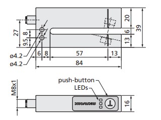 |
esf-1/CDF/A 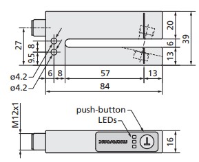 |
esf-1/7/CDF/A 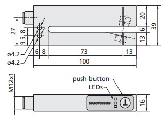 |
esf-1/15/CDF/A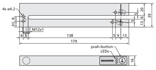 |
| fork depth | 6 mm | 6 mm | 6 mm | 6 mm |
| transducer frequency | 70 mm | 70 mm | 86 mm | 165 mm |
| working range | 500 kHz | 500 kHz | 500 kHz | 500 kHz |
| web material with grammages of | web material with grammages of | web material with grammages of | web material with grammages of | |
| paper and films up to 0.2 mm thick, self-adhesive films, | <20 g/m2 to >>400 g/m2 , metal-laminated | <20 g/m² to >>400 g/m², metal-laminated | <20 g/m² to >>400 g/m², metal-laminated | |
| <20 g/m² to >>400 g/m², metal-laminated | paper and films up to 0.2 mm thick, self-adhesive films, | paper and films up to 0.2 mm thick, self-adhesive films, | paper and films up to 0.2 mm thick, self-adhesive films, | |
| operating voltage Us | labels on backing material | labels on backing material | labels on backing material | labels on backing material |
| operating voltage ripple | 20 to 30 V DC, reverse polarity protection (Class 2) | 20 to 30 V DC, reverse polarity protection (Class 2) | 20 to 30 V DC, reverse polarity protection (Class 2) | 20 to 30 V DC, reverse polarity protection (Class 2) |
| no-load current consumption | ±10% | ±10 % | ±10% | ±10% |
| type of connection | <50 mA | ≤50 mA | ≤50 mA | ≤50 mA |
| controls | 5-pin M12 initiator plug | 5-pin M12 initiator plug | 5-pin M12 initiator plug | 5-pin M12 initiator plug |
| scope of settings | Teach-in push-button, control input Pin 5 | Teach-in push-button, control input Pin 5 | Teach-in push-button, control input Pin 5 | Teach-in push-button, control input Pin 5 |
| response time | Teach-in, IO-Link, LinkControl | Teach-in, IO-Link, LinkControl | Teach-in, IO-Link, LinkControl | Teach-in, IO-Link, LinkControl |
| indicators: | 300 µs to 2 ms, depending on the material | 300 µs to 2 ms, depending on the material | 300 µs to 2 ms, depending on the material | 300 µs to 2 ms, depending on the material |
| LED green: working/backing material | LED green: working/backing material | LED green: working/backing material | LED green: working/backing material | |
| LED yellow: label/splice | LED yellow: label/splice | LED yellow: label/splice | LED yellow: label/splice LED red: web break | |
| LED red: web break | LED red: web break | LED red: web break | LEDs flash: Teach-in dismissed | |
| IO-Link | LEDs flash: Teach-in dismissed | LEDs flash: Teach-in dismissed | LEDs flash: Teach-in dismissed | V1.1 |
| housing | V1.1 | V1.1 | V1.1 | aluminium anodized; plastic parts: PBT, PA; |
| aluminium anodized; plastic parts: PBT, PA; | aluminium anodized; plastic parts: PBT, PA; | aluminium anodized; plastic parts: PBT, PA; | ultrasonic transducer: polyurethane, | |
| ultrasonic transducer: polyurethane, | ultrasonic transducer: polyurethane, | ultrasonic transducer: polyurethane, | epoxy resin with glass content | |
| class of protection to EN 60529 | epoxy resin with glass content | epoxy resin with glass content | epoxy resin with glass content | IP 65 |
| operating temperature | IP 65 | IP 65 | IP 65 | +5 to +60 °C |
| storage temperature | +5 to +60 °C | +5 to +60 °C | +5 to +60 °C | -40 to +85 °C |
| weight | -40 to +85 °C | –40 to +85 °C | -40 to +85 °C | 160 g |
| norm conformity: | 80 g | 80 g | 90 g | EN 60947-5-2 |
| time delay before availibility | EN 60947-5-2 | EN 60947-5-2 | EN 60947-5-2 | <300 ms |
| <300 ms. | <300 ms | <300 ms | ||
| order no. | esf-1/15/CDF/A | |||
| label/splice output F | esf-1/CF/A | esf-1/CDF/A | esf-1/7/CDF/A | push-pull, +U-3 V, U+3 V, Imax= 100 mA, |
| push-pull, +U-3 V, U+3 V, 100 mA, | push-pull, +UB–3 V, –UB+3 V, I max. = 100 mA, | push-pull, +U-3 V, U+3 V. Imax= 100 mA, | short-circuit-proof, switchable NOC/NCC | |
| web break output D | short-circuit-proof, switchable NOC/NCCpnp, +UB–3 V, Imax.= 100 mA, | short-circuit-proof, switchable NOC/NCC pnp, +U | short-circuit-proof, switchable NOC/NCC | pnp, +Ue-3 V, Imax= 100 mA, |
| short-circuit-proof, switchable NOC/NCC | B–3 V, Imax.= 100 mA, | pnp, +U-3 V, Imax. 100 mA, | short-circuit-proof, switchable NOC/NCC |
microsonic GmbH / Phoenixseestraße 7 / 44263 Dortmund / Germany / T +49 231 975151-0 / F +49 231 975151-51 / E info@microsonic.de / W microsonic.de
The content of this document is subject to technical changes. Specifications in this document are presented in a descriptive way only. They do not warrant any product features.
![]() Enclosure Type 1
Enclosure Type 1
For use only in industrial
machinery NFPA 79 applications.
The proximity switches shall be used with a Listed
(CYJV/7) cable/connector assembly rated minimum
32 Vdc, minimum 290 mA, in the final installation.![]()

Documents / Resources
 |
microsonic esf-1-CF-A Ultrasonic Label and Splice Sensor [pdf] Instruction Manual esf-1-CF-A, esf-1-CDF-A, esf-1-7-CDF-A, esf-1-15-CDF-A, esf-1-CF-A Ultrasonic Label and Splice Sensor, esf-1-CF-A, Ultrasonic Label and Splice Sensor, Label and Splice Sensor, and Splice Sensor, Splice Sensor, Sensor |