![]() AN3500
AN3500
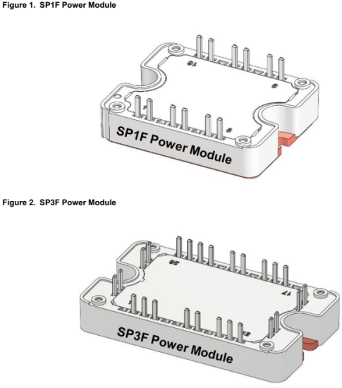
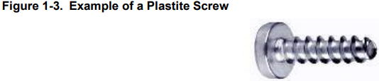
Mounting Instructions for SP1F and SP3F Power Modules
Introduction
This application note gives the main recommendations to appropriately connect the printed circuit board (PCB) to the SP1F or the SP3F power module and mount the power module onto the heat sink. Follow the mounting instructions to limit both thermal and mechanical stresses.
PCB Mounting Instructions
The PCB mounted on the power module can be screwed to the standoffs to reduce all mechanical stress and minimize relative movements on the pins that are soldered to the power module.
Step 1: Screw the PCB to the standoffs of the power module.
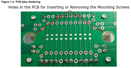
 A self-tapering plastite screw with a nominal diameter of 2.5 mm is recommended to attach the PCB. A plastite screw, shown in the following figure, is a type of screw specifically designed for use with plastic and other low-density materials. The screw length depends on the PCB thickness. With a 1.6 mm (0.063”) thick PCB, use a plastite screw 6 mm (0.24”) long. The maximum mounting torque is 0.6 Nm (5 lbf·in). Check the integrity of the plastic post after tightening the screws.
 Step 2: Solder all electrical pins of the power module to the PCB as shown in the following figure.
A no-clean solder flux is required to attach the PCB, as the aqueous module cleaning is not allowed.
Note: Do not reverse these two steps, because if all pins are soldered first to the PCB, screwing the PCB to the standoffs creates a deformation of the PCB, leading to some mechanical stress that can damage the tracks or break the components on the PCB.
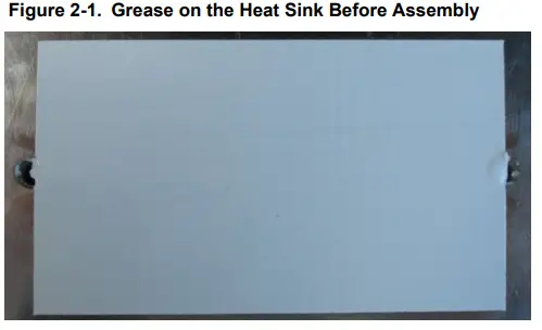
Holes in the PCB as shown in the preceding figure are necessary to insert or remove the mounting screws that bolt down the power module to the heat sink. These access holes must be large enough for the screw head and washers to pass through freely, allowing for normal tolerance in PCB hole location. The PCB hole diameter for the power pins is recommended at 1.8 ± 0.1 mm. The PCB hole diameter for inserting or removing the mounting screws is recommended at 10 ± 0.1 mm.
For efficient production, a wave soldering process can be used to solder the terminals to the PCB. Each application, heat sink and PCB can be different; wave soldering must be evaluated on a case-by-case basis. In any case, a wellbalanced
layer of solder should surround each pin.
The gap between the bottom of the PCB and the power module is 0.5 mm to 1 mm only as shown in PCB Mounted on Power Module figure. Using through-hole components on the PCB is not recommended. SP1F or SP3F pinout can change according to the configuration. See the product datasheet for more information on the pin-out location.
Power Module Mounting Instructions
Proper mounting of the module base plate onto the heat sink is essential to guarantee good heat transfer. The heat sink and the power module contact surface must be flat (recommended flatness should be less than 50 μm for 100 mm continuous, recommended roughness Rz 10) and clean (no dirt, corrosion, or damage) to avoid mechanical stress when power module is mounted, and to avoid an increase in thermal resistance.
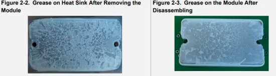
Step 1: Thermal grease application: To achieve the lowest case to heat sink thermal resistance, a thin layer of thermal grease must be applied between the power module and the heat sink. It is recommended to use screen printing technique to ensure a uniform deposition of a minimum thickness of 60 μm (2.4 mils) on the heat sink as shown in the following figure. The thermal interface between the module and the heat sink can also be made with other conductive thermal interface materials such as phase change compound (screen-printed or adhesive layer).
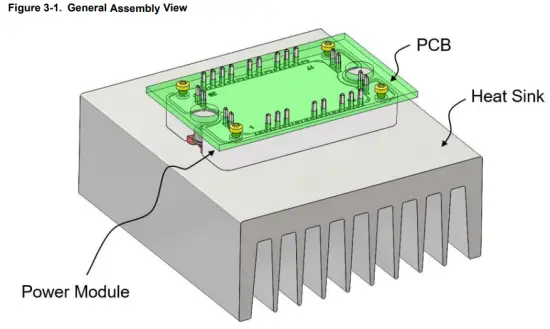
Step 2: Mounting the power module onto the heat sink: Place the power module above heat sink holes and apply a small pressure to it. Insert the M4 screw with lock and flat washers in each mounting hole (a #8 screw can be used instead of M4). The screw length must be at least 12 mm (0.5”). First, lightly tighten the two mounting screws. Tighten alternatively the screws until their final torque value is reached (see the product datasheet for the maximum torque allowed). It is recommended to use a screwdriver with controlled torque for this operation. If possible, screws can be tightened again after three hours. The quantity of thermal grease is correct when a small amount of grease appears around the power module once it is bolted down onto the heat sink with the appropriate mounting torque. The lower surface of the module must be completely wet with thermal grease as shown in the Grease on the Module After Disassembling figure. The gap between the screws, top height and the nearest terminal must be checked to maintain safe insulation spacing.
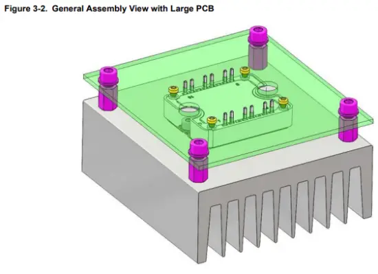
General Assembly View
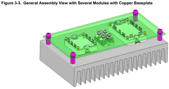
 If a large PCB is used, additional spacers between the PCB and the heat sink are necessary. It is recommended to keep a distance of at least 5 cm between the power module and the spacers as shown in the following figure. The spacers must be of the same height as the standoffs (12 ± 0.1 mm).
For specific applications, some SP1F or SP3F power modules are manufactured with an AlSiC (Aluminium Silicon Carbide) baseplate (M suffix in the part number). AlSiC baseplate is 0.5 mm thicker than the copper baseplate, so the spacers must be 12.5 ± 0.1 mm in thickness.
The SP1F and SP3F plastic frame height is the same height as a SOT-227. On the same PCB, if a SOT-227 and one or several SP1F/SP3F power modules with copper baseplate are used, and if the distance between the two power modules does not exceed 5 cm, it is not necessary to install the spacer as shown in the following figure.
If a SP1F/SP3F power modules with AlSiC baseplate is used with a SOT-227 or other SP1F/SP3F modules with copper baseplate, the heatsink height must be reduced by 0.5 mm under the SP1F/SP3F modules with an AlSiC baseplate to maintain all the module standoffs at the same height.
Care must be taken with heavy components like electrolytic or polypropylene capacitors, transformers, or inductors. If these components are located in the same area, it is recommended to add spacers even if the distance between two modules does not exceed 5 cm such that, the weight of these components on the board is not handled by the power module but by the spacers. In any case, each application, heat sink, and PCB are different; the spacers placement must be evaluated on a case-by-case basis.
Conclusion
This application note gives the main recommendations regarding the mounting of SP1F or SP3F modules. Applying these instructions helps decrease the mechanical stress on PCB and power module, while ensuring long term operation of the system. Mounting instructions to the heat sink must also be followed to achieve the lowest thermal resistance from the power chips down to the cooler. All these steps are essential to guarantee the best system reliability.
Revision History
The revision history describes the changes that were implemented in the document. The changes are listed by revision, starting with the most current publication.
| Revision | Date | Description |
| A | May-20 | This is the initial release of this document. |
The Microchip Website
Microchip provides online support via our website at www.microchip.com/. This website is used to make files and information easily available to customers. Some of the content available includes:
- Product Support – Data sheets and errata, application notes and sample programs, design resources, user’s guides and hardware support documents, latest software releases and archived software
- General Technical Support – Frequently Asked Questions (FAQs), technical support requests, online discussion groups, Microchip design partner program member listing
- Business of Microchip – Product selector and ordering guides, latest Microchip press releases, listing of seminars and events, listings of Microchip sales offices, distributors and factory representatives
Product Change Notification Service
Microchip’s product change notification service helps keep customers current on Microchip products. Subscribers will receive email notification whenever there are changes, updates, revisions or errata related to a specified product family or development tool of interest. To register, go to www.microchip.com/pcn and follow the registration instructions.
Customer Support
Users of Microchip products can receive assistance through several channels:
- Distributor or Representative
- Local Sales Office
- Embedded Solutions Engineer (ESE)
- Technical Support
Customers should contact their distributor, representative or ESE for support. Local sales offices are also available to help customers. A listing of sales offices and locations is included in this document.
Technical support is available through the website at: www.microchip.com/support
Microchip Devices Code Protection Feature
Note the following details of the code protection feature on Microchip devices:
- Microchip products meet the specification contained in their particular Microchip Data Sheet.
- Microchip believes that its family of products is one of the most secure families of its kind on the market today, when used in the intended manner and under normal conditions.
- There are dishonest and possibly illegal methods used to breach the code protection feature. All of these methods, to our knowledge, require using the Microchip products in a manner outside the operating specifications contained in Microchip’s Data Sheets. Most likely, the person doing so is engaged in theft of intellectual property.
- Microchip is willing to work with the customer who is concerned about the integrity of their code.
- Neither Microchip nor any other semiconductor manufacturer can guarantee the security of their code.
Code protection does not mean that we are guaranteeing the product as “unbreakable.” Code protection is constantly evolving. We at Microchip are committed to continuously improving the code protection features of our products. Attempts to break Microchip’s code protection feature may be a violation of the Digital Millennium Copyright Act. If such acts allow unauthorized access to your software or other copyrighted work, you may have a right to sue for relief under that Act.
Legal Notice
Information contained in this publication regarding device applications and the like is provided only for your convenience and may be superseded by updates. It is your responsibility to ensure that your application meets with your specifications. MICROCHIP MAKES NO REPRESENTATIONS OR WARRANTIES OF ANY KIND WHETHER EXPRESS OR IMPLIED, WRITTEN OR ORAL, STATUTORY OR OTHERWISE, RELATED TO THE INFORMATION,
INCLUDING BUT NOT LIMITED TO ITS CONDITION, QUALITY, PERFORMANCE, MERCHANTABILITY OR FITNESS FOR PURPOSE. Microchip disclaims all liability arising from this information and its use. Use of Microchip devices in life support and/or safety applications is entirely at the buyer’s risk, and the buyer agrees to defend, indemnify and hold harmless Microchip from any and all damages, claims, suits, or expenses resulting from such use. No licenses are conveyed, implicitly or otherwise, under any Microchip intellectual property rights unless otherwise stated.
Trademarks
The Microchip name and logo, the Microchip logo, Adaptec, AnyRate, AVR, AVR logo, AVR Freaks, BesTime, BitCloud, chipKIT, chipKIT logo, CryptoMemory, CryptoRF, dsPIC, FlashFlex, flexPWR, HELDO, IGLOO, JukeBlox, KeeLoq, Kleer, LANCheck, LinkMD, maXStylus, maXTouch, MediaLB, megaAVR, Microsemi, Microsemi logo, MOST, MOST logo, MPLAB, OptoLyzer, PackeTime, PIC, picoPower, PICSTART, PIC32 logo, PolarFire, Prochip Designer, QTouch, SAM-BA, SenGenuity, SpyNIC, SST, SST Logo, SuperFlash, Symmetricom, SyncServer, Tachyon, TempTrackr, TimeSource, tinyAVR, UNI/O, Vectron, and XMEGA are registered trademarks of Microchip Technology Incorporated in the U.S.A. and other countries.
APT, ClockWorks, The Embedded Control Solutions Company, EtherSynch, FlashTec, Hyper Speed Control, Hyperlight Load, Intel limos, Libero, motorBench, mTouch, Powermite 3, Precision Edge, ProASIC, ProASIC Plus, ProASIC Plus logo, Quiet-Wire, SmartFusion, SyncWorld, Temux, TimeCesium, TimeHub, TimePictra, TimeProvider, Vite, WinPath, and ZL are registered trademarks of Microchip Technology Incorporated in the U.S.A. Adjacent Key Suppression, AKS, Analog-for-the-Digital Age, Any Capacitor, AnyIn, AnyOut, BlueSky, BodyCom, CodeGuard, CryptoAuthentication, Crypto Automotive, Crypto Companion, Crypto Controller, dsPICDEM, dsPICDEM.net, Dynamic Average Matching, DAM, ECAN, EtherGREEN, In-Circuit Serial Programming, ICSP, INICnet, Inter-Chip Connectivity, Jitter Blocker, KleerNet, KleerNet logo, memBrain, Mindi, MiWi, MPASM, MPF, MPLAB Certified logo, MPLIB, MPLINK, MultiTRAK, NetDetach, Omniscient Code Generation, PICDEM, PICDEM.net, PICkit, PICtail, PowerSmart, PureSilicon, QMatrix, REAL ICE, Ripple Blocker, SAM-ICE, Serial Quad I/O, SMART-I.S., SQI, SuperSwitcher, SuperSwitcher II, Total Endurance, TSHARC, USBCheck, VariSense, ViewSpan, WiperLock, Wireless DNA, and ZENA are trademarks of Microchip Technology Incorporated in the U.S.A. and other countries.
SQTP is a service mark of Microchip Technology Incorporated in the U.S.A. The Adaptec logo, Frequency on Demand, Silicon Storage Technology, and Symmcom are registered trademarks of Microchip Technology Inc. in other countries.
GestIC is a registered trademark of Microchip Technology Germany II GmbH & Co. KG, a subsidiary of Microchip Technology Inc., in other countries.
All other trademarks mentioned herein are property of their respective companies.
© 2020, Microchip Technology Incorporated, Printed in the U.S.A., All Rights Reserved. ISBN: 978-1-5224-6145-6
Quality Management System
For information regarding Microchip’s Quality Management Systems, please visit www.microchip.com/quality.
Worldwide Sales and Service
| AMERICAS | ASIA/PACIFIC | ASIA/PACIFIC | EUROPE |
| Corporate Office 2355 West Chandler Blvd. Chandler, AZ 85224-6199 Tel: 480-792-7200 Fax: 480-792-7277 Technical Support: www.microchip.com/support Web Address: www.microchip.com Atlanta Duluth, GA Tel: 678-957-9614 Fax: 678-957-1455 Austin, TX Tel: 512-257-3370 Boston Westborough, MA Tel: 774-760-0087 Fax: 774-760-0088 Chicago Itasca, IL Tel: 630-285-0071 Fax: 630-285-0075 Dallas Addison, TX Tel: 972-818-7423 Fax: 972-818-2924 Detroit Novi, MI Tel: 248-848-4000 Houston, TX Tel: 281-894-5983 Indianapolis Noblesville, IN Tel: 317-773-8323 Fax: 317-773-5453 Tel: 317-536-2380 Los Angeles Mission Viejo, CA Tel: 949-462-9523 Fax: 949-462-9608 Tel: 951-273-7800 Raleigh, NC Tel: 919-844-7510 New York, NY Tel: 631-435-6000 San Jose, CA Tel: 408-735-9110 Tel: 408-436-4270 Canada – Toronto Tel: 905-695-1980 Fax: 905-695-2078 |
Australia – Sydney Tel: 61-2-9868-6733 China – Beijing Tel: 86-10-8569-7000 China – Chengdu Tel: 86-28-8665-5511 China – Chongqing Tel: 86-23-8980-9588 China – Dongguan Tel: 86-769-8702-9880 China – Guangzhou Tel: 86-20-8755-8029 China – Hangzhou Tel: 86-571-8792-8115 China – Hong Kong SAR Tel: 852-2943-5100 China – Nanjing Tel: 86-25-8473-2460 China – Qingdao Tel: 86-532-8502-7355 China – Shanghai Tel: 86-21-3326-8000 China – Shenyang Tel: 86-24-2334-2829 China – Shenzhen Tel: 86-755-8864-2200 China – Suzhou Tel: 86-186-6233-1526 China – Wuhan Tel: 86-27-5980-5300 China – Xian Tel: 86-29-8833-7252 China – Xiamen Tel: 86-592-2388138 China – Zhuhai Tel: 86-756-3210040 |
India – Bangalore Tel: 91-80-3090-4444 India – New Delhi Tel: 91-11-4160-8631 India – Pune Tel: 91-20-4121-0141 Japan – Osaka Tel: 81-6-6152-7160 Japan – Tokyo Tel: 81-3-6880- 3770 Korea – Daegu Tel: 82-53-744-4301 Korea – Seoul Tel: 82-2-554-7200 Malaysia – Kuala Lumpur Tel: 60-3-7651-7906 Malaysia – Penang Tel: 60-4-227-8870 Philippines – Manila Tel: 63-2-634-9065 Singapore Tel: 65-6334-8870 Taiwan – Hsin Chu Tel: 886-3-577-8366 Taiwan – Kaohsiung Tel: 886-7-213-7830 Taiwan – Taipei Tel: 886-2-2508-8600 Thailand – Bangkok Tel: 66-2-694-1351 Vietnam – Ho Chi Minh Tel: 84-28-5448-2100 |
Austria – Wels Tel: 43-7242-2244-39 Fax: 43-7242-2244-393 Denmark – Copenhagen Tel: 45-4485-5910 Fax: 45-4485-2829 Finland – Espoo Tel: 358-9-4520-820 France – Paris Tel: 33-1-69-53-63-20 Fax: 33-1-69-30-90-79 Germany – Garching Tel: 49-8931-9700 Germany – Haan Tel: 49-2129-3766400 Germany – Heilbronn Tel: 49-7131-72400 Germany – Karlsruhe Tel: 49-721-625370 Germany – Munich Tel: 49-89-627-144-0 Fax: 49-89-627-144-44 Germany – Rosenheim Tel: 49-8031-354-560 Israel – Ra’anana Tel: 972-9-744-7705 Italy – Milan Tel: 39-0331-742611 Fax: 39-0331-466781 Italy – Padova Tel: 39-049-7625286 Netherlands – Drunen Tel: 31-416-690399 Fax: 31-416-690340 Norway – Trondheim Tel: 47-72884388 Poland – Warsaw Tel: 48-22-3325737 Romania – Bucharest Tel: 40-21-407-87-50 Spain – Madrid Tel: 34-91-708-08-90 Fax: 34-91-708-08-91 Sweden – Gothenberg Tel: 46-31-704-60-40 Sweden – Stockholm Tel: 46-8-5090-4654 UK – Wokingham Tel: 44-118-921-5800 Fax: 44-118-921-5820 |
© 2020 Microchip Technology Inc.
Application Note DS00003500A-page 10
Documents / Resources
 |
MICROCHIP SP1F, SP3F Power Modules [pdf] Instruction Manual AN3500, SP1F SP3F Power Modules, SP1F SP3F, Power Modules, Modules |