![]() MIPI CSI-2 Transit FMC
MIPI CSI-2 Transit FMC
Quickstart Guide
Introduction
Microchip offers an FPGA-based MIPI CSI-2 transmit reference solution with PolarFire® and PolarFire SoC FPGAs. It is transceiver-enabled, which upgrades our GPIO-based IP solution to support data rates of up to 2.5 Gbps/lane and facilitate 4K video data. It complements our MIPI CSI-2 receiver IP and is part of our extensive Smart Embedded Vision Portfolio of IPs and a popular choice for vision applications at the edge.
The MIPI Transmit FMC Card works with the PolarFire® Video and Imaging Kit and PolarFire SoC Video Kit.
Table 1-1. VIDEO-DC-MIPITX Contents
| Description | Quantity |
| MIPI TX FMC daughter board | 1 |
| Quickstart Card | 1 |
| Flexible Printed Circuit (FPC) Cable, 200 mm: 22 to 15 Pin | 1 |
Figure 1-1. VIDEO-DC-MIPITX Board

1.1 Hardware Features
The MIPI TX FMC daughter card supports the following hardware features:
- D-PHY 2.5 Gbps
- Nine GPIOs
- 4 × Transceivers
1.2 Demo Requirements
The following table contains the hardware and software required for running the demo.
Table 1-2. Hardware and Software Requirements
| Requirement | Description |
| Hardware | |
| PolarFire® video kit | MPF300-VIDEO-KIT-NS kit contents: • PolarFire video and imaging board with MPF300T-1FCG1152E device • HDMI cable • 12V power pack/AC adapter • USB 2.0 A male to mini-B |
| MIPITx FMC daughter card | VIDEO-DC-MIPITX |
| MIPI cable | MIPI 22 to 15-pin cable |
| Raspberry Pi | Raspberry Pi 4 model B |
| USB keyboard and mouse | USB keyboard and mouse as input devices for Raspberry Pi |
| 5V power pack/AC adapter | Power adapter with type C cable that supports 5V/3A, or as per RPi’s minimum requirements |
| SD card | SD card (16 GB or 0) of any class |
| Micro HDMIcable | Micro HDMI to HDMI type to connect to monitor to Raspberry Pi |
| HDMI monitor | To connect Raspberry Pi Micro HDMI (port 0 or port 1) to HDMI of monitor |
| Software | |
| Linux® | Ubuntu v20.4 For more details about running the demo, see Raspberry Pi SD Card Setup and Run section. |
| Libero® SoC Design Suite | FlashPro Express is installed as part of Libero SoC Design Suite version 12.0 or later releases. |
1.3 Demo Setup
Before you begin with demo, ensure to download the following files from AN5494: MIPI CSI-2 Transmitter:
- mpf_an5494_v2024p1_jb – Job file to test on Raspberry Pi
- mipi_csi2_tx_using_rpi.zip – Raspberry Pi image file
Demo setup comprises two parts:
- Setting up the hardware
- Programming the device
1.3.1 Setting up the Hardware
Setting up the hardware involves verifying the jumper settings and interfacing the MIPI Transmit FMC (VIDEO-DC-MIPITX) card with the PolarFire video kit, along with the MIPI cable.
The following figure shows the MIPITX call out.
Figure 1-2. MIPITX Call Out
The following figure shows the demo setup for the MIPI Transmit FMC (VIDEO-DC-MIPITX) card.
Figure 1-3. Setting up the Demo
The following table lists the jumper and switch settings of PolarFire video kit.
Table 1-3. Jumper and Switch Settings of PolarFire Video Kit
| Jumper and Switch | Position | Description |
| J15 | Open | SPI Target and Initiator mode selection. By default, select SPI Initiator |
| J14 | MIPI Transmit FMC | MIPI Transmit FMC to be connected |
| J17 | Open | 100K PD for TRSTn |
| J19 | Pin 1 and 2 | Default: XCVR_VREF is connected to ground |
| J28 | Pin 1 and 2 | Default: Programming through the FTDI |
| J6 | Pin 1 and 3 | Default: VDDAUX4 voltage is set to 2.5V |
| J25 | Pin 9 and 10 | Bank4 voltage |
| J36 | Pin 1 and 2 | Default: Board power-up through the SW4 |
| SW4 | OFF or ON | Power On or Off slide switch |
| J20 | 12 Volts Input | 12V input to the board |
| J12 | USB-UART | USB-UART mini cable |
For setting up the hardware, perform the following steps:
- Ensure that the preceding jumper settings in table are set on the video kit. For more details, see Figure 1-2.
- Connect the MIPI TX daughter card to J14 of the FMC connector of the PolarFire video kit, see Figure 1-2.
- Connect the ribbon cable between the MIPI Transmit FMC card and the Raspberry Pi J3 camera connector (see Figure 1-3).
- Connect the host PC and the video kit through J12 of the video kit using the USB mini cable.
- Connect the 12V power supply cable to the J20 on board DC jack of the video kit.
- Power-up the board using the SW4 slide switch.
- Connect the 5V power supply cable to the USB type C Power In socket of the Raspberry Pi.
- Connect the USB keyboard and USB mouse to the Raspberry Pi.
- Power-up the Raspberry Pi and HDMI monitor. (Raspberry Pi splash screen on the HDMI monitor appears.)
- After the power-up, program the PolarFire Video Kit device. For more information, see the Programming the PolarFire Device section.
- After programming the PolarFire device, the Raspberry Pi SD card setup needs to be done, and the test pattern generator starts streaming the video data as seen in when running the demo, see Raspberry Pi SD Card Setup and Run section.
1.3.2 Programming the PolarFire Device
This section describes how to program the PolarFire Video Kit device with the job file using FlashPro
Express. The job file mpf_an5494_v2024p1_jb to test on Raspberry Pi is provided in the AN5494: MIPI CSI-2 Transmitter.
To program the PolarFire device, perform the following steps:
- On the host PC, start the FlashPro Express software from its installation directory.
- To create a new job project on the Project menu, click New or New Job Project from FlashPro Express Job.
- In the New Job Project from FlashPro Express Job dialog box, perform the following steps:
– Programming job file: Click Browse and navigate to the location where the job file is located and select the file.
– FlashPro Express job project location: Select Browse and navigate to the location where you want to save the project. - Click OK. The required programming file is selected and ready to be programmed in the device.
The FlashPro Express window appears. - Verify that a programmer number appears in the Programmer box. If it does not, verify the board connections and click Refresh/Rescan Programmers.
- To program the device, click RUN. When the device is programmed successfully, a RUN PASSED status is displayed.
- To close FlashPro Express, click Project > Exit.
1.4 Setting up the Demo
The following sections describe the demo set up and run process.
1.4.1 Setting up the Raspberry Pi 4
For setting up Raspberry Pi 4, perform the following steps:
- Connect the HDMI monitor to the HDMI0 port of the Raspberry Pi.
- Connect the ribbon cable between the MIPI Transmit FMC card and the Raspberry Pi J3 camera connector as shown in the Fig 1.3
- Connect the 5V power supply cable to the USB type C Power In socket of the Raspberry Pi 4 Model B.
- Connect the USB keyboard and USB mouse to the Raspberry Pi 4 Model B.
- Power-up the Raspberry Pi 4 Model B and HDMI monitor.
Raspberry Pi SD card setup needs to be done. For information about the steps related to setup, see Raspberry Pi SD Card Setup and Run section.
1.4.2 Raspberry Pi SD Card Setup and Run
The following steps and associated commands are necessary to enable the Raspberry Pi to detect the PolarFire-based MIPI TX as a camera source.
- Download and extract the mipi csi2 tx_using_rpi.zip to get mipi_csi2_tx_using_rpi_vl.img file.
- Download and install rpi-imager from raspberry pi website based on your Operating System (OS), that is, Windows or Linux.
- Insert SD card (atleast 16 GB) to the host system. The host system can be either windows or Linux which runs the rpi-imager.
- Run rpi-manager and perform the following steps:
a. Click on CHOOSE OS under Operating System field and then select the option Use custom. Navigate and select the extracted raspberry pi image mentioned in step1.
b. Click on CHOOSE STORAGE under Storage field and select SD card that is inserted to the system.
c. To start writing image to the SD card, click on WRITE. This process may take 15 to 20 min. - Insert SD card in the Raspberry Pi SD card slot.
- Power on Raspberry Pi and login once Raspberry Pi boots.
This section describes the following commands that must be run on a Raspberry Pi.
- Open Ubuntu terminal.
- To view the kernal release number, enter uname – command.
The output appears as kernal release: 6.1.20v71+. - Issue the following V4L2 command to configure and wait for CSI data reception.
a. v4L2-ctl –device=/dev/video–set-fmt-video=width=1920,height=1080,pixelformat=RGGB –stream-mmap –stream-to-test.raw –stream-count=1
Note: If the command is stuck and does not finish executing, it means data reception is not working.
b. Do not stop or kill the command. While the command is running, restart PolarFire device using SW4 switch and check if data is received. If data not received even after restarting the board at least ten times, recheck the ribbon cable connection (given that every step is followed correctly.)
c. If the command returns with the “<” symbol, it means data reception is successful.
Note: Before power cycling the video kit, “<” may appear. It is acceptable.
d. Issue the following command to stream the data live from the PolarFire video kit board. sudo ffplay -f video4linux2 -input format bayer_rggb8-1/dev/video
e. Another window appears with the test pattern from the video kit. For more details, see MIPI CSI-2 Transmitter Validation section.
1.4.2.1 MIPI CSI-2 Transmitter Validation
Output Pattern 1:
The following figure shows the output pattern of the MIPI CSI-2 Transmitter with transceiver for a data rate of 800 Mbps/Lane for Full HD resolution at 30 FPS (1920 x 1080 at 30 FPS) and uses a 2 lane MIPI configuration is tested with the Raspberry Pi 4 model B.
Figure 1-4. Test Pattern—RPi
Output Pattern 2:
The following figure shows the output pattern of the MIPI CSI-2 Transmitter for 2.5 Gbps per lane with XCVR tested with the MIPI Introspect Analyzer (SV3C – DPRX 4-Lane D-PHY Analyzer).
Figure 1-5. Test Pattern—MIPI Analyzer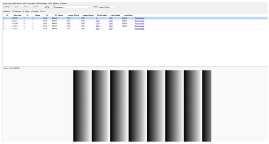
![]() Important: The MIPI Analyzer capture shows 1920 x 1080 video at 126 FPS using one MIPI CSI-2 lane. At this rate, the four-lane connection supports 4K video at 60 FPS.
Important: The MIPI Analyzer capture shows 1920 x 1080 video at 126 FPS using one MIPI CSI-2 lane. At this rate, the four-lane connection supports 4K video at 60 FPS.
1.5 Document References
For more information including schematics and user guides, refer to the following links:
Microchip FPGA Support
Microchip FPGA products group backs its products with various support services, including Customer Service, Customer Technical Support Center, a website, and worldwide sales offices.
Customers are suggested to visit Microchip online resources prior to contacting support as it is very likely that their queries have been already answered.
Contact Technical Support Center through the website at www.microchip.com/support. Mention the FPGA Device Part number, select appropriate case category, and upload design files while creating a technical support case.
Contact Customer Service for non-technical product support, such as product pricing, product upgrades, update information, order status, and authorization.
- From North America, call 800.262.1060
- From the rest of the world, call 650.318.4460
- Fax, from anywhere in the world, 650.318.8044
Microchip Information
Trademarks
The Microchip name and logo, the Microchip logo, Adaptec, AVR, AVR logo, AVR Freaks, BesTime, BitCloud, CryptoMemory, CryptoRF, dsPIC, flexPWR, HELDO, IGLOO, JukeBlox, KeeLoq, Kleer, LANCheck, LinkMD, maXStylus, maXTouch, MediaLB, megaAVR, Microsemi, Microsemi logo, MOST, MOST logo, MPLAB, OptoLyzer, PIC, picoPower, PICSTART, PIC32 logo, PolarFire, Prochip Designer, QTouch, SAM-BA, SenGenuity, SpyNIC, SST, SST Logo, SuperFlash, Symmetricom, SyncServer, Tachyon, TimeSource, tinyAVR, UNI/O, Vectron, and XMEGA are registered trademarks of Microchip Technology Incorporated in the U.S.A. and other countries.
AgileSwitch, ClockWorks, The Embedded Control Solutions Company, EtherSynch, Flashtec, Hyper Speed Control, HyperLight Load, Libero, motorBench, mTouch, Powermite 3, Precision Edge, ProASIC, ProASIC Plus, ProASIC Plus logo, Quiet-Wire, SmartFusion, SyncWorld, TimeCesium, TimeHub, TimePictra, TimeProvider, and ZL are registered trademarks of Microchip Technology Incorporated in the U.S.A.
Adjacent Key Suppression, AKS, Analog-for-the-Digital Age, Any Capacitor, AnyIn, AnyOut, Augmented Switching, BlueSky, BodyCom, Clockstudio, CodeGuard, CryptoAuthentication, CryptoAutomotive, CryptoCompanion, CryptoController, dsPICDEM, dsPICDEM.net, Dynamic Average Matching, DAM, ECAN, Espresso T1S, EtherGREEN, EyeOpen, GridTime, IdealBridge, IGaT, In-Circuit Serial Programming, ICSP, INICnet, Intelligent Paralleling, IntelliMOS, Inter-Chip Connectivity, JitterBlocker, Knob-on-Display, MarginLink, maxCrypto, maxView, memBrain, Mindi, MiWi, MPASM, MPF, MPLAB Certified logo, MPLIB, MPLINK, mSiC, MultiTRAK, NetDetach, Omniscient Code Generation, PICDEM, PICDEM.net, PICkit, PICtail, Power MOS IV, Power MOS 7, PowerSmart, PureSilicon, QMatrix, REAL ICE, Ripple Blocker, RTAX, RTG4, SAM-ICE, Serial Quad I/O, simpleMAP, SimpliPHY, SmartBuffer, SmartHLS, SMART-I.S., storClad, SQI, SuperSwitcher, SuperSwitcher II, Switchtec, SynchroPHY, Total Endurance, Trusted Time, TSHARC, Turing, USBCheck, VariSense, VectorBlox, VeriPHY, ViewSpan, WiperLock, XpressConnect, and ZENA are trademarks of Microchip Technology Incorporated in the U.S.A. and other countries.
SQTP is a service mark of Microchip Technology Incorporated in the U.S.A.
The Adaptec logo, Frequency on Demand, Silicon Storage Technology, and Symmcom are registered trademarks of Microchip Technology Inc. in other countries.
GestIC is a registered trademark of Microchip Technology Germany II GmbH & Co. KG, a subsidiary of Microchip Technology Inc., in other countries.
All other trademarks mentioned herein are property of their respective companies.
© 2025, Microchip Technology Incorporated and its subsidiaries. All Rights Reserved.
ISBN: 979-8-3371-0410-2
AMBA, Arm, Arm7, Arm7TDMI, Arm9, Arm11, Artisan, big.LITTLE, Cordio, CoreLink, CoreSight, Cortex, DesignStart, DynamIQ, Jazelle, Keil, Mali, Mbed, Mbed Enabled, NEON, POP, RealView, SecurCore, Socrates, Thumb, TrustZone, ULINK, ULINK2, ULINK-ME, ULINK-PLUS, ULINKpro, µVision, Versatile are trademarks or registered trademarks of Arm Limited (or its subsidiaries) in the US and/or elsewhere.
Legal Notice
This publication and the information herein may be used only with Microchip products, including to design, test, and integrate Microchip products with your application. Use of this information in any other manner violates these terms. Information regarding device applications is provided only for your convenience and may be superseded by updates. It is your responsibility to ensure that your application meets with your specifications. Contact your local Microchip sales office for additional support or, obtain additional support at www.microchip.com/en-us/support/design-help/client-support-services.
THIS INFORMATION IS PROVIDED BY MICROCHIP “AS IS”. MICROCHIP MAKES NO REPRESENTATIONS OR WARRANTIES OF ANY KIND WHETHER EXPRESS OR IMPLIED, WRITTEN OR ORAL, STATUTORY OR OTHERWISE, RELATED TO THE INFORMATION INCLUDING BUT NOT LIMITED TO ANY IMPLIED WARRANTIES OF NON-INFRINGEMENT, MERCHANTABILITY, AND FITNESS FOR A PARTICULAR PURPOSE, OR WARRANTIES RELATED TO ITS CONDITION, QUALITY, OR PERFORMANCE.
IN NO EVENT WILL MICROCHIP BE LIABLE FOR ANY INDIRECT, SPECIAL, PUNITIVE, INCIDENTAL, OR CONSEQUENTIAL LOSS, DAMAGE, COST, OR EXPENSE OF ANY KIND WHATSOEVER RELATED TO THE INFORMATION OR ITS USE, HOWEVER CAUSED, EVEN IF MICROCHIP HAS BEEN ADVISED OF THE POSSIBILITY OR THE DAMAGES ARE FORESEEABLE. TO THE FULLEST EXTENT ALLOWED BY LAW, MICROCHIP’S TOTAL LIABILITY ON ALL CLAIMS IN ANY WAY RELATED TO THE INFORMATION OR ITS USE WILL NOT EXCEED THE AMOUNT OF FEES, IF ANY, THAT YOU HAVE PAID DIRECTLY TO MICROCHIP FOR THE INFORMATION.
Use of Microchip devices in life support and/or safety applications is entirely at the buyer’s risk, and the buyer agrees to defend, indemnify and hold harmless Microchip from any and all damages, claims, suits, or expenses resulting from such use. No licenses are conveyed, implicitly or otherwise, under any Microchip intellectual property rights unless otherwise stated.
Microchip Devices Code Protection Feature
Note the following details of the code protection feature on Microchip products:
- Microchip products meet the specifications contained in their particular Microchip Data Sheet.
- Microchip believes that its family of products is secure when used in the intended manner, within operating specifications, and under normal conditions.
- Microchip values and aggressively protects its intellectual property rights. Attempts to breach the code protection features of Microchip product is strictly prohibited and may violate the Digital Millennium Copyright Act.
- Neither Microchip nor any other semiconductor manufacturer can guarantee the security of its code. Code protection does not mean that we are guaranteeing the product is “unbreakable”. Code protection is constantly evolving. Microchip is committed to continuously improving the code protection features of our products.
![]() Online Reference
Online Reference
© 2025 Microchip Technology Inc. and its subsidiaries
DS50003688B
Documents / Resources
 |
MICROCHIP MIPI CSI-2 Transit FMC [pdf] User Guide MIPI CSI-2 Transit FMC, MIPI CSI-2, Transit FMC |