Microbrain ITS-AX3-4 Vehicle Detection Sensor
Please carefully read this manual before installation Thank you for purchasing our barrier anti-smash-ing radar product. To ensure that the radar can perform at its best, please read this user manual carefully and install and operate strictly according to the manual. The copyright of this product’s hardware and software design is protected by law and shall not be infringed by any unit or individual. In order to further improve the quality and performance, the specifications and design of this product may be changed without prior notice. Please understand.
Introduction
- The Vehicle detection radar for the gate is developed for the management needs of entrance and exit management such as parking lots and underground garages.
- It can accurately control the rise and fall of the gate bar by working in coordination with the gate machine main control board. At the same time, it can effectively prevent the gate bar from “accidentally injuring” the target passing through the radar field of view, realizing intelligent anti-smashing.
- The radar adopts a highly integrated RF chip SoC solution, which has the characteristics of small size, low cost, all-day and all-weather operation, high detection sensitivity, high accuracy, simple debugging and installation, and stable and reliability.
- The operating frequency of this radar is 60-64GHz, using a linear frequency modulation continuous waveform and a distance resolution of up to 4cm. The millimeter wave antenna adopts a multi-transmit and multi-receive method, with high angular resolution and angle measurement accuracy.
- Through the joint optimization design of software and hardware, this product can accurately identify and distinguish pedestrians, vehicles and other targets passing through the gate bar area, avoiding phenomena such as “smashing cars”, “smashing people”, and “not falling bars”.
Technical Specifications
| Feature | Parameter | Technical indicators |
|
System Properties |
Operating Voltage | 9-24V (12V/1A) |
| Operating temperature | -40℃~ +85℃ | |
| Power | < 0.5W | |
| Protect level | IP55 | |
| Communication interface |
RS485;Bluetooth |
|
| Shell Size | 107.6*73.3*18.3mm | |
|
Detect Range |
Detection width |
The default setting is
±0.5 meters, and can be customized within ±1.5 meters according to actual conditions. |
| Detection distance | 1-6m(Default 3m) | |
| Upgrade & debug | Online debug | 485;Bluetooth |
| Online upgrade | 485;Bluetooth | |
| Application | Straight boom barrier
3.Features |
|
Features
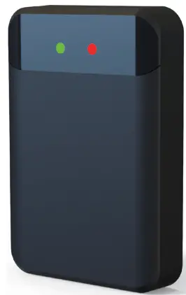
The appearance of the radar is shown in Figure 1. Its main features are:
LED indicator:
- There are two LED indicators on the front of the sensor. The red one is the power light, which stays on after the power is turned on; the green one is the status light, which turns on when a target is detected in the area and turns off when the target disappears;
Detection area configuration:
- The default sensing area of the sensor is 3 meters forward, and different detection areas can be set through the mobile phone app or computer debugging software;
Configuration parameter saving:
- Can automatically save the detection area and other configurations, and use the most recently saved configuration parameters after power failure and restart;
Firmware upgrade:
- No need to disassemble and install, upgrade the firmware online through 485/Bluetooth interface, and restart the sensor after the upgrade is completed to take effect;
Stable performance:
- The sensor operation is not affected by external environment such as light, dust, rain and snow.
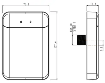
- Appearance and dimensions of Vehicle detection sensor
Installation Instructions
- The sensor should be installed on the surface of barrier gate box and vertically to the ground. The installation must follow the below steps:
Step 1: Confirm the radar installation hole position
- The inner side of the straight rod is 200-300mm away from the radar installation hole position, 650-750mm from the lane ground (not the safety island) (for cars and vans), 750-800mm (for trucks with chassis higher than 700mm); the installation position is shown in Figure 2.
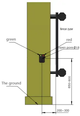
- Schematic diagram of the installation location of the sensor
Step 2: Installation hole
- Use an electric drill to drill a fixing hole suitable for M16 at the selected position of the gate box. The recom-mended hole drill bit diameter is 18mm.
Step 3: Installation and Fixing
- As shown in the figure below, the radar is fixed to the gate box through the bottom bolts (torque value is less than 20N.m). First, insert the radar into the gate box, then cover it with a gasket and tighten it with an M16 screw, then insert the wiring harness end downward into the radar and tighten the metal buckle. The final installation effect is shown in Figure 3.
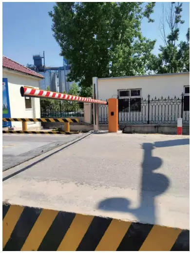
- Gate radar installation effect diagram
Cable interface definition
| No | Cable ID | Color | Description |
| 1 | 12V | Red | Positive |
| 2 | GND | Black | Negative |
| 3
4 |
B-/RX
A+/TX |
White
Gray |
485 B-
485 A+ |
| 5 | NO1 | Blue | Normally open1 |
| 6 | NO1 | Green | Normally open1 |
| 7 | NC2 | Brown | Normally Close2 |
| 8 | NC2 | Purple | Normally Close2 |
The wiring harness functions and connection relationships are as follows:
Power connection
- The red wire “12V” is connected to the positive output terminal of the 12V power supply;
- The black wire “GND” is connected to the negative output terminal of the 12V power supply.
Gate control signal
- The green and blue wires are relay normally open signals, connecting the ground sensor coil terminal and the common terminal (not distinguishing between positive and negative) of the gate control box.
485 line connection
- Gray wire connects to the T/R+ end of the 485 line; White wire connects to the T/R- end of the 485 line.
Bluetooth connection
- Bluetooth name: “Radar…” or “Mbit…”; User password: 88888888.
Configuration Instructions
- The sensor can be configured by mobile App or the computer software.
Mobile App configuration:
- After installing the mobile debugging app, open the software as shown in Figure 4, click Connect Device, as shown in Figure 5, and select Bluetooth pairing connection with “Radar…”
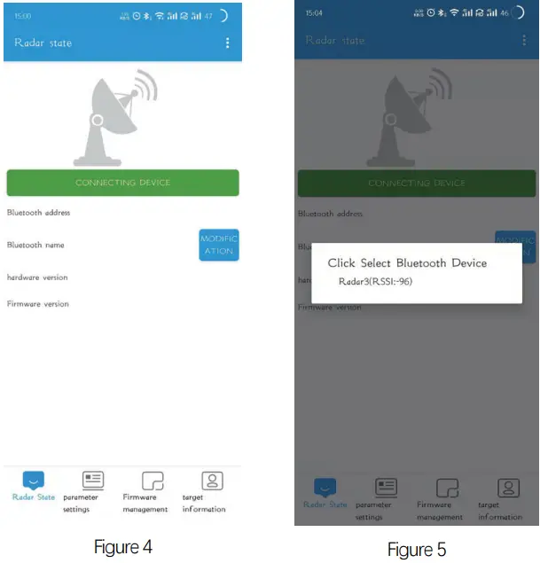
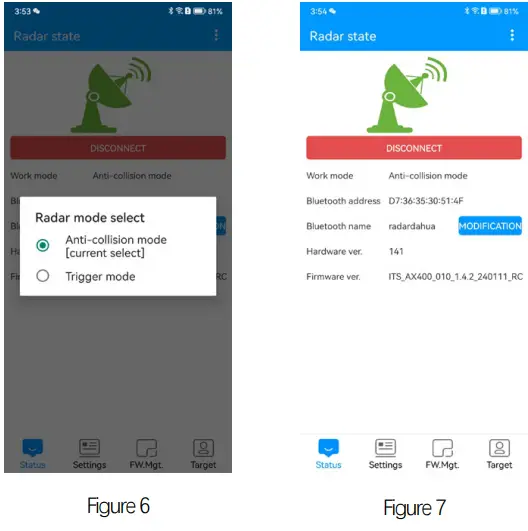
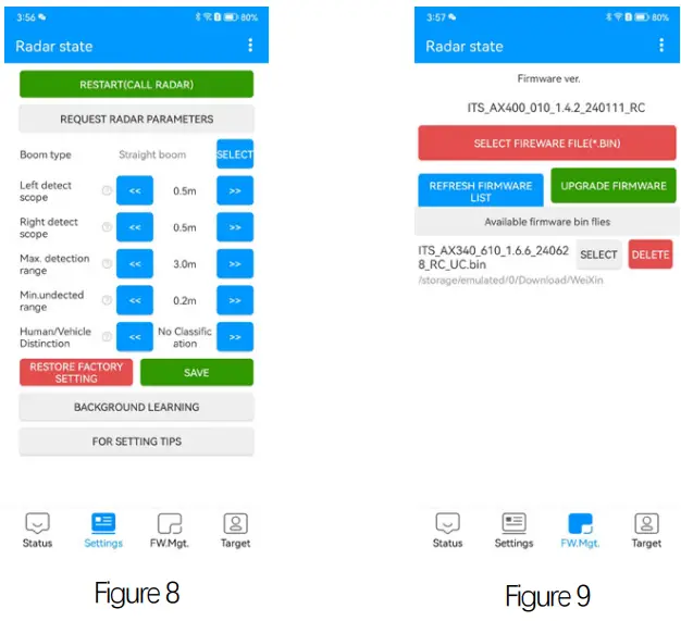
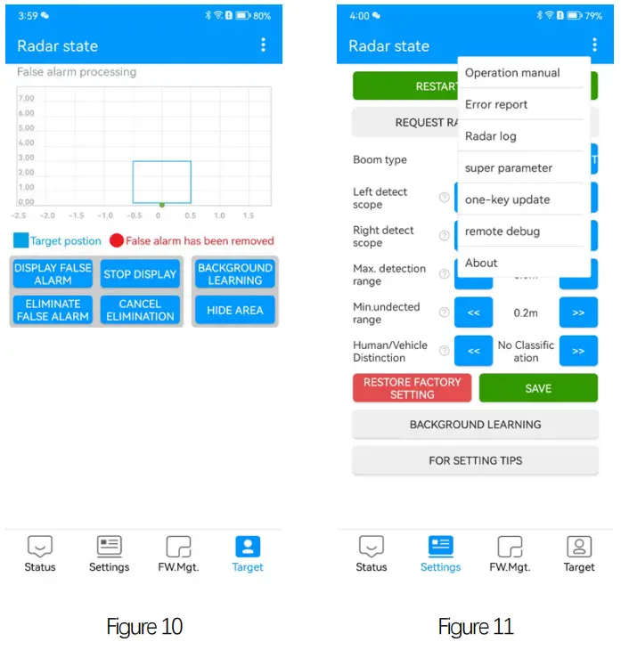
- After connection, select radar mode, as shown in Figure 6, and enter the app interface as shown in Figure 8, Figure 9, Figure 10, and Figure 11.
- You can modify the sensor parameters and learn the background according to the actual environment on site. For radar firmware upgrade, select the firmware and click Upgrade Firmware, then wait for the upgrade to complete.
- After background learning is completed, you can click Display False Alarm to view false alarms. During the display of false alarms, please do not perform other operations except stopping the display.
- For other detailed operations, please refer to the product manual and APP manual.
Computer software debugging instructions
Step1:
- Use USB to 485 cable to connect the radar to the computer. For radar interface, please refer to “5. Cable interface description”.
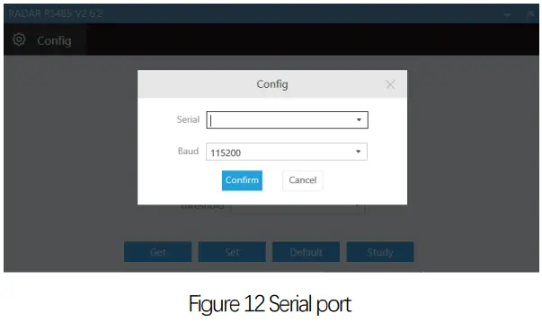
Step2:
- Open the debugging software, select the serial port and baud rate, and click “Confirm”.
Step3:
- You can first click the Get button to query the current setting parameters of the radar.
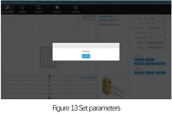
Step4:
- Enter the required setting parameters in the corresponding options, select “Reset” to save the sensor
Radar parameter description
| Parameter Explanation | |
|
Maximum front distance |
The default value is 3 meters, which needs to be set according to the length of the barrier pole. |
|
Minimum front distance |
The default setting is 0.2 meters, which is the radar’s close-range non-detec- tion range and can be adjusted based on site conditions. |
| Left range | The default setting is ±0.5 meters,and the straight pole can be customized within ±1.5 meters according to actual conditions. |
| Right range | |
|
Barrier Type |
The default barrier type is “straight arm” |
|
Log |
Record the sensor relay status when the vehicle passes by |
- Click Reset to make the new setting parameters effective after restart of radar.
- Click “get” to get the current radar configuration.
- Click “factory settings” to restore the default configuration of radar.
Step5:
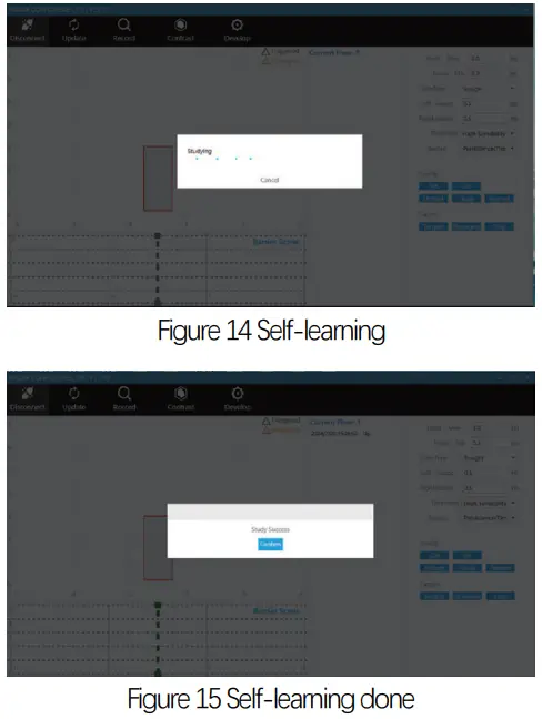
- After the settings are completed, click “Self-learn-ing” to learn and record the environmental background. After the operation is completed, restart the radar to take effect.
- For straight-pole type barriers, make sure there are no movable targets in the radar detection area, lift the straight pole, and then click “Self-learning”.
- Wait for 6 seconds and restart the radar. The interface during learning is as follows:
- After learning is completed, please click the soft restart button to restart the sensor.
Notes:
- During “self-learning”, make sure there are no movable targets in the sensor detection area. If a target enters or passes through the sensor detection area during the process of learning and recording the environmental background, the sensor needs to be restarted and re-learned;
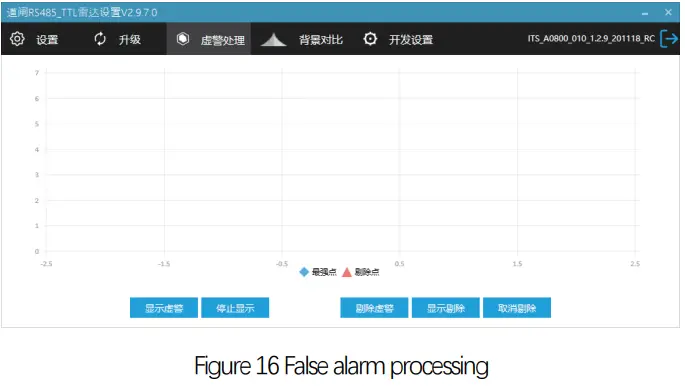
Step6: Check sensor interference
When debugging the sensor for the first time, after the environment learning is completed, you can use this function to check whether there is interference in front of the sensor.
- Open the debugging software.
- Select “False Alarm Handling”.
- Click “Show False Alarm” to view target information.
- Click “Remove False Alarm” to remove false alarm interference.
- If there is no target interference within the detection range of the stick, the radar can be used normally.
Precautions
- The power supply voltage is stable to avoid affecting the performance of the radar. It is recommended to use a separate external 12V/1A power adapter for power supply.
- The radar antenna is integrated inside. When the radar surface is covered with foreign objects (such as water droplets, frost, rain, snow, dust, etc.) that affect the normal operation of the radar, it should be cleaned in time.
- After the detection environment changes (such as installing guide columns, ice cream cones, etc. in the detection area), please re-learn and record the environment.
- The radar’s detection field of view cannot have objects that affect target detection (such as metal fences, billboards, license plate recognition cameras, walls, etc.) to avoid interference with the radar.
- It is not recommended to use the radar in single-channel mixed-in and mixed-out scenarios with fences and billboard poles installed.
- It is recommended to use a dual radar installation solution or remote control of the gate rod in scenarios where there are semi-trailers, cement tankers, etc. with a body gap of more than 1 meter.
- This product is not recommended to be deployed on muddy roads. Extreme weather (heavy rain, heavy snow) may affect the stability of radar performance.
- In general, please set the detection distance according to the length of the pole. The detection distance should be slightly less than or equal to the length of the pole to prevent people or objects outside the gate from passing through and being detected by the radar.
- When learning and recording the environment, the straight pole may shake when it falls to the ground after the pole is dropped. Wait until the pole is completely stable before performing subsequent operations.
- If there is a bounce pole caused by the radar, please re-learn the background.
- When a strong metal scattering object (such as an iron plate) such as a speed bump is located directly in front of the radar, the radar installation height is 750-800mm.
- If you need to install a radar in a special environment, please contact our company first, and then install it correctly according to the suggestions.
Common fault description
- Fault phenomenon: After installation, the green light of the radar is always on and the pole does not fall.
- Possible cause: There is a new enhanced reflector within the radar detection range, which needs to be moved out of the radar field of view or re-learning the background.
- Fault phenomenon: The green light does not light up when a person stands in front of the radar.
- Possible cause: The human-vehicle distinction function is enabled. After the vehicle triggers the radar green light to light up, the radar starts to detect whether the person or the vehicle is distinguished.
- Fault phenomenon: After the radar is connected to the 12V power supply of the gate control board, the red light flashes and the power supply is insufficient.
- Possible cause: It is recommended to connect an external 12V-1A power adapter for power supply.
Packing list
| No | Parts | Qty |
| 1 | Sensor | 1 |
| 2 | M16 nut | 1 |
| 3 | Gasket | 1 |
| 4 | Wire harness | 1 |
| 5 | Certificate | 1 |
| 6 | User Manual | 1 |
FCC Statement
Any Changes or modifications not expressly approved by the party responsible for compliance could void the user’s authority to operate the equipment. This device complies with part 15 of the FCC Rules. Operation is subject to the following two conditions:
- This device may not cause harmful interference, and
- This device must accept any interference received, including interference that may cause undesired operation.
FCC Radiation Exposure Statement:
- This equipment complies with FCC radiation exposure limits set forth for an uncontrolled environment.This transmitter must not be co‐located or operating in conjunction with any other antenna or transmitter.This equipment should be installed and operated with minimum distance 20cm between the radiator& your body.
Note :
- This equipment has been tested and found to comply with the limits for a Class B digital device, pursuant to part 15 of the FCC Rules.
- These limits are designed to provide reasonable protection against harmful interference in a residential installation.
- This equipment generates,uses and can radiate radio frequency energy and, if not installed and used in accordance with the instructions, may cause harmful interference to radio communications.
- However, there is no guarantee that interference will not occur in a particular installation.
- If this equipment does cause harmful interference to radio or television reception, which can be determined by turning the equipment off and on, the user is encouraged to try to correct the interference by one or more of the following measures:
- Reorient or relocate the receiving antenna.
- Increase the separation between the equipment and receiver.
- Connect the equipment into an outlet on a circuit different from that to which the receiver is connected.
- Consult the dealer or an experienced radio/TV technician for help.
Frequently Asked Questions
Q: Can the detection range be adjusted?
A: Yes, the detection range can be adjusted through the mobile app or computer software.
Q: How to upgrade the firmware?
A: The firmware can be upgraded online through the 485/Bluetooth interface without disassembly.
Documents / Resources
 |
Microbrain ITS-AX3-4 Vehicle Detection Sensor [pdf] User Manual ITS-AXX-XX, ITS-AX3-4 Vehicle Detection Sensor, ITS-AX3-4, Vehicle Detection Sensor, Detection Sensor, Sensor |