![]()
 Brief description
FSM 2.0 – STO
for the ARS 2000 FS series servo drives
Translation of the original instructions
FSM 2.0 – STO Safety Module
![]() You will find the complete documentation on the safety module as well as the documentation on the servo drive ARS 2000 FS in PDF format on our homepage at http://www.metronix.de.
You will find the complete documentation on the safety module as well as the documentation on the servo drive ARS 2000 FS in PDF format on our homepage at http://www.metronix.de.
This brief description refers to the following versions:
− Safety module FSM 2.0 – STO, from revision 1.5.
− Servo drive ARS 2000 FS, firmware from version 4.0.0.1.7.
Safety
1.1 General safety information
- In addition, always observe the “Safety notes for electrical drives and controllers“ on the servo drives ARS 2000 FS. You will find these in the respective product manuals.
![]() Note
Note
Danger of loss of the safety function!
Non-compliance with environmental and connection conditions can lead to loss of the safety function.
- Observe the specified environmental and connection conditions, in particular the input voltage tolerances Section 12.
![]() Note
Note
Incorrect handling can damage the safety module or the servo drive.
Incorrect handling can result in damage.
- Before mounting and installation work, switch off the supply voltage. Switch on the supply voltage only when the mounting and installation work is complete.
- Never unplug a module from, or plug a module into the servo drive when it is energised!
- Observe the handling specifications for electrostatically-sensitive devices.
1.2 Intended use
The safety module FSM 2.0 – STO serves as an expansion of the servo drives ARS 2000 FS to achieve the safety function:
− Safely switched-off torque – “Safe Torque Off” (STO) with SIL3 according to EN 61800-5-2 / EN 62061 / IEC 61508 or category 4 / PL e according to EN ISO 13849-1.
The servo drive ARS 2000 FS with safety module FSM 2.0 – STO is a product with safety-relevant functions and is intended for installation in machines or automation systems and for use as follows:
− in a faultless technical condition,
− in its original condition, without any modifications by the user,
− within the product’s limits as defined by the technical data (![]() Section 12),
Section 12),
− in an industrial environment.
The Functional Safety Modules FSM 2.0 can be operated in all servo drives of the product family ARS 2000 FS. Those are equipped with the slot for safety modules (“FSM slot”). The safety modules cannot be inserted into one of the extension slots for technology modules (TECH1 or TECH2).
![]() Note
Note
In the event of damage caused by unauthorised manipulation or use other than intended, the guarantee is invalidated and the manufacturer is not liable for damages.
1.3 Possible incorrect application
Improper use includes the following possible cases of incorrect application:
− use in a device other than the servo drive ARS 2000 FS,
− use outdoors,
− use in a non-industrial area (residential area),
− use in applications where switching off can result in hazardous movements or conditions.
![]() Note
Note
− The STO function is insufficient as the sole safety function for drives subject to permanent torque (e.g. suspended loads).
− Bypassing of safety equipment is impermissible.
− Repairs on the module are impermissible!
The STO (Safe Torque Off) function does not provide protection against electric shock, only against hazardous movements!
![]() Product manual ARS 2100 FS, product manual ARS 2300 FS and product manual / mounting instructions “Servo drives ARS 2320 FS, ARS 2340 FS and ARS 2360W FS”
Product manual ARS 2100 FS, product manual ARS 2300 FS and product manual / mounting instructions “Servo drives ARS 2320 FS, ARS 2340 FS and ARS 2360W FS”
1.4 Achievable safety level,
Safety function according to EN ISO 13849-1 / EN 61800-5-2
The safety module fulfils the basic test requirements
− Category 4 / PL e according to EN ISO 13849-1,
− SIL CL 3 according to EN 61800-5-2 / EN 62061 / IEC 61508, and can be used in applications up to cat. 4 / PL e according to EN ISO 13849-1 and SIL 3 according to EN 62061 / IEC 61508.
The achievable safety level depends on the other components used to achieve a safety function.
Requirements for product use
- Make this documentation available to the design engineer and installer or person responsible for commissioning the machine or system in which this product will be used.
- Ensure compliance with specifications in the documentation at all times. Also take into account the documentation for the other components and modules (e.g. servo drive, lines, etc.).
- Take into account the legal regulations applicable to the destination, as well as:
− regulations and standards,
− regulations of the testing organisations and insurers,
− national specifications. - For emergency stop applications, protection against automatic restart must be provided according to the required safety category. This can be achieved through an external safety switching device, for example.
2.1 Technical requirements
General conditions for the correct and safe use of the product, which must be observed at all times:
- Comply with the connection and environmental conditions of the safety module (
 Section 12), the servo drive and all connected components.
The product can be operated in accordance with the relevant safety guidelines only if the limit values or load limits are observed. - Observe the warnings and instructions in this documentation.
2.2 Qualification of the specialist personnel (requirements for personnel)
The device may only be placed in operation by a qualified electrical engineer who is familiar with:
− installation and operation of electrical control systems,
− the applicable regulations for operating safety-engineered systems,
− the applicable regulations for accident protection and occupational safety, and − product documentation.
2.3 Diagnostic coverage (DC)
Diagnostic coverage depends on the connection between the servo drive with safety module and the control loop system as well as the implemented diagnostic measures ![]() Section 9.
Section 9.
If a potentially hazardous disturbance is recognised during diagnosis, appropriate measures for maintaining the safety level must be implemented.
![]() Note
Note
Check whether cross-circuit detection of the input circuit and the connection wiring is required in your application.
If needed, use a safety switching device with horizontal cross-circuit detection to activate the safety module.
2.4 Range of applications and certification
The servo drive with built-in safety module is a safety component in accordance with the machinery directive; the servo drive bears the CE mark.
Standards and test values which the product must comply with and fulfils can be found in the section “Technical data “(![]() Section 12).The product-relevant EU directives can be found in the declaration of conformity.
Section 12).The product-relevant EU directives can be found in the declaration of conformity.
![]() Certificates and the declarations of conformity for this product can be found at http://www.metronix.de.
Certificates and the declarations of conformity for this product can be found at http://www.metronix.de.
Product description
3.1 Supported devices
The safety module FSM 2.0 – STO can only be used in servo drives in conformity with Section 1.2.
As a standard, the ARS 2000 FS series servo drives come supplied with the module FSM 2.0 – FBA without integrated functional safety mounted in the FSM slot.
3.2 Control sections and connections
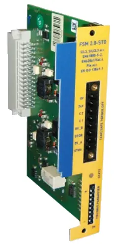
The safety module FSM 2.0 – STO has the following control sections, connections and display components: 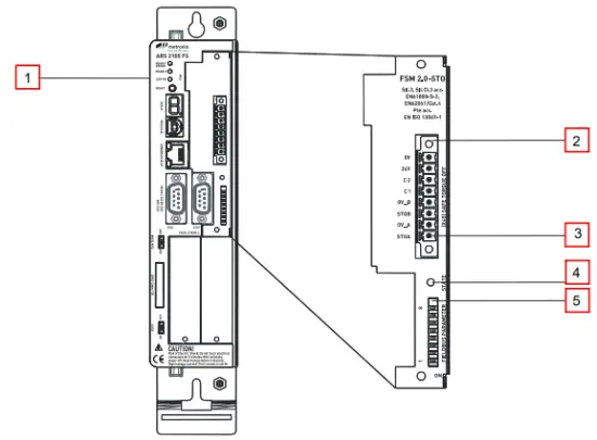 Figure 1: Operator panel and connections FSM 2.0 – STO
- Servo drive ARS 2000 FS with slot for a Functional Safety Module
- Digital I/O-interface [X40] for control of the STO function
- Pin 1 of the interface [X40]
- LED for status display (functional safety status)
- DIP-switch (activation / configuration of the fieldbus communication in the servo drive)
Function and application
The safety module FSM 2.0 – STO has the following performance characteristics:
− “Safe Torque Off” (STO) function,
− Potential-free feedback contact
− Designed as a plug-in module that can be plugged in from the outside,
− Suitable solely for series ARS 2000 FS servo drives.
4.1 Description of the safety function
The power supply to the drive is safely disconnected with the active safety function STO “Safe Torque Off”. The drive cannot generate torque and so cannot make any dangerous movements. There is no monitoring of the standstill position.
The machine must be stopped in a safety-oriented manner, e.g. through a safety switch device. This applies specifically to vertical axes without automatic-locking mechanism, clamping unit or counterbalancing.
![]() Note
Note
There is a risk that the drive will advance in case of multiple errors in the ARS 2000 FS.
If the output stage of the servo drive fails while in the STO status (simultaneous short circuit of 2 power semiconductors in different phases), a limited dwell movement of the rotor may result. The rotation angle / path corresponds to a pole pitch. Examples:
− Rotary ax is, synchronous machine, 8 -pin ![]() movement < 45° at the motor shaft.
movement < 45° at the motor shaft.
− Linear motor, pole pitch 20 mm ![]() movement < 20 mm at the moving part.
movement < 20 mm at the moving part.
4.2 Control ports STO-A, 0V_A / STO-B, 0V_B [X40]
The safety function STO is requested solely through switching off of the control voltage (0 V) at the two digital control ports STO-A and STO-B. Safety-oriented circuitry for additional interfaces at the ARS 2000 FS basic unit is not necessary or intended.
![]() Cross-circuit detection in the input circuit is not carried out by the safety module.
Cross-circuit detection in the input circuit is not carried out by the safety module.
According to the specification of the safety function, both levels must be identical at STO-A/B, otherwise an error message will be generated. The finite state machine in the servo drive internally monitors the driver supply voltage as a result of activation of the control ports. The level change for both inputs must take place within the discrepancy time (preset: 100 ms), otherwise an error message will be generated.
Recommendation: Always switch STO-A and STO-B simultaneously.
Temporary test impulses from safety controls are tolerated and thus do not trigger the STO function.
4.3 Feedback contact C1, C2 [X40]
The status of the servo drive is reported back to an external safety switch device through a floating feedback contact (normally open).
![]() The feedback contact is designed as a single channel and may be used for diagnostic purposes, but not in the safety circuit.
The feedback contact is designed as a single channel and may be used for diagnostic purposes, but not in the safety circuit.
Mounting / Dismounting
The safety module FSM 2.0 – STO is suitable only for integration into the servo drives ARS 2000 FS. It cannot be operated outside the servo drive.
The servo drive must be disconnected from all current carrying cables before mounting and dismounting the safety module.
![]() Warning
Warning
![]() Danger of electric shock if the safety module is not mounted.
Danger of electric shock if the safety module is not mounted.
Contact with conducting parts will cause severe injuries and may result in death.
Before touching conducting parts during maintenance, repair and cleaning work and during long service interruptions:
- Switch off the power to the electrical equipment and secure it to prevent a restart.
- After switching it off, wait at least 5 minutes of discharge time and check that it is voltage-free before accessing the servo drive.
![]() Note
Note
Incorrect handling can damage the safety module or servo drive.
- Before mounting and installation work, switch off the supply voltage. Switch on the supply voltage only when the mounting and installation work have been completely finished.
- Never unplug a module from, or plug a module into the servo drive when it is energised!
- Observe the handling specifications for electrostatically-sensitive devices. Do not touch the printed circuit board or the pins of the manifold rail in the servo drive. Hold the safety module only by the front plate or the edge of the board.
Mounting the safety module
- Insert the safety module FSM 2.0 – STO into the extension slot for safety modules so that the board runs in the lateral guides of the slot.
- Insert safety module; when the back of the contact strip within the servo drive is reached, carefully press it into the contact strip until it stops.
- Then screw the safety module with the two screws onto the front of the servo drive housing.
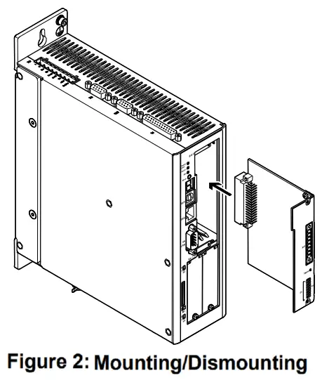
Tighten the screws with approx. 0.35 Nm.
Dismounting the safety module
- Unscrew screws on the safety module.
- Loosen the safety module by gently levering the front cover or by pulling on the counterplug by just a few millimetres.
- Pull the safety module out of the slot.
Electrical installation
6.1 Safety instructions
During installation, the requirements of EN 60204-1 must be fulfilled.
![]() Warning
Warning
![]() Danger of electric shock in case of voltage sources without safety measures.
Danger of electric shock in case of voltage sources without safety measures.
- Use only PELV (protective extra-low voltage) circuits according to EN 60204-1 for the electric logic supply.
Also observe the general requirements for PELV power circuits according to EN 60204-1. - Only use power sources which guarantee reliable electrical isolation of the operating voltage according to EN 60204-1.
Protection against electric shock (protection against direct and indirect contact) is guaranteed in accordance with EN 60204-1 by using PELV circuits (electrical equipment of machines, general requirements). The 24 V power supply unit used in the system must satisfy the requirements of EN 60204-1 for DC power supply (behaviour during power interruptions, etc.).
![]() Make sure that no jumpers or the like can be inserted parallel to the safety wiring, e.g. through the use of the maximum wire cross section of 1.5 mm² or suitable wire end sleeves with insulating collars. Use twin wire end sleeves for looping through lines between neighbouring devices.
Make sure that no jumpers or the like can be inserted parallel to the safety wiring, e.g. through the use of the maximum wire cross section of 1.5 mm² or suitable wire end sleeves with insulating collars. Use twin wire end sleeves for looping through lines between neighbouring devices.
6.2 ESD protection
With non-assigned plug connectors, there is a danger of the device that other parts of the system may be damaged as a result of ESD (electrostatic discharge). Earth the system parts prior to installation and use suitable ESD equipment (e.g. shoes, earthing straps, etc.).
6.3 Connection [X40]
The FSM 2.0 – STO safety module has a combined interface for control and acknowledgment via the plug connector [X40].
| Plug | Pin | Designation | Value | Description |
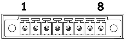 |
8 | 0V | 0 V | Reference potential for auxiliary power supply. |
| 7 | 24V | +24 V DC | Auxiliary power supply (24 V DC logic supply of the servo drive carried out). | |
| 6 | C2 | – | Feedback contact for the status “STO” on an external controller. | |
| 5 | C1 | |||
| 4 | 0V-B | 0 V | Reference potential for STO-B. | |
| 3 | STO-B | 0 V / 24 V | Control port B for the function STO. | |
| 2 | 0V-A | 0 V | Reference potential for STO-A. | |
| 1 | STO-A | 0 V / 24 V | Control port A for the function STO. |
Figure 3: Pin assignment [X40] (representation of the plug on the module)
In order to ensure the STO “Safe Torque Off” functions correctly, the control ports STO-A and STO-B are to be connected in two channels with parallel wiring.
This interface can be part of an emergency stop circuit or a protective door arrangement, for example. Figure 4: Connection of the safety module FSM 2.0 – STO, example of single-phase servo drive ARS 2000 FS
- Servo drive with safety module (only relevant connections illustrated
- Emergency stop switch
- Protective door
- Light curtain
- Safety switching device
If a safety oriented interface is (still) not present, the fieldbus activation module FSM 2.0 – FBA should be used.
If no fieldbus activation module is available or for the initial start-up of the servo drive without safety equipment, the servo drive ARS 2000 FS with the safety module FSM 2.0 – STO can be equipped with an emergency stop switch (2) with minimum wiring as per Figure 4.
Carry out the minimum wiring of the inputs STO-A/STO-B and 0V-A/0V-B for the initial start-up so that it will be forcibly removed when the final protection wiring is executed.
![]() Note
Note
Safety functions must never be bypassed.
Commissioning
![]() Warning
Warning
Danger in the event of Loss loss of the safety function!
Lack of the safety function can result in serious, irreversible injuries, e.g. due to uncontrolled movements of the connected actuators.
- Operate the safety module only:
− in a built-in condition and
− when all safety measures have been implemented. - Validate the safety function to complete commissioning
- Incorrect wiring, use of an incorrect safety module or external components that were not selected according to the safety category, result in loss of the safety function.
- Carry out a risk evaluation for your application and select the circuitry and components accordingly.
7.1 Before commissioning
Perform the following steps to prepare for commissioning:
- Ensure that the safety module is correctly mounted.
- Check the electrical installation (connecting cable, pin allocation Section 0). Are all protective earth conductors connected?
7.2 DIP switch setting
Set the DIP switches as described in the documentation for the servo drives ARS 2000 FS or the corresponding fieldbus-specific product manuals.
7.3 Parameterisation with Metronix ServoCommander™
When a modification is detected, e.g. a module replacement, a non-acknowledgeable error is triggered. To be able to place the application with the servo drive back in operation, the modification must be “configured”. That means, the modification must be explicitly accepted or confirmed.
The configuration is performed in the window Safety module of the Metronix ServoCommanderTM.
7.4 Function test
![]() Note
Note
The STO function must be validated after the installation and after changes to the installation.
This validation must be documented by the person performing commissioning.
To help you with commissioning, you can find sample checklists in the product manual “FSM 2.0 – STO”.
Operation
8.1 Obligations of the operator
The operational capability of the safety equipment must be checked at adequate intervals. It is the responsibility of the operator to choose the type of check and time intervals in the specified time period. The check must be made in a way that proves proper functioning of the safety equipment in interaction with all components.
8.2 Maintenance and care
The safety module does not require any maintenance.
Diagnostics and troubleshooting
9.1 Status indicators
Operating mode and malfunctions are displayed directly on the two-colour LED of the safety module.
| LED | Designation | Description |
| Off | Not safe = STO status not active | Safety module or servo drive has no operating voltage. |
| Green | Not safe = STO status not active | The power output stage in the servo drive for supply of the motor can be active or inactive. |
| Yellow | Safe = STO status active | The power output stage in the servo drive for supply of the motor is switched off safely. |
Figure 5 LED display on the safety module
| Display | Description |
| “H”: The servo drive is in the “safe status”.
This does not have the same meaning as the information on the status of the safety function STO (Safe Torque Off). This can only be read off on the LED of the safety module. No special display is intended for the “unsafe status”; the normal status displays of the servo drive are represented. |
Figure 6: Seven segment display on the servo drive
9.2 Error messages
When an error occurs, the servo drive shows an error message cyclically in the seven-segment display on the front of the servo drive. The error message consists of an E (for Error), a main index (xx) and sub-index (y), e.g.: E 5 1 0.
Warnings have the same number as an error message. The difference is that a warning is displayed with a prefixed and suffixed hyphen, e.g. – 1 7 0 -.
Figure 7 lists the error messages that are relevant for the functional safety in combination with the safety module FSM 2.0 – STO.
![]() For more information about other error messages, please refer to the corresponding documentation, for example the relevant product manuals, the software manual or the fieldbus- specific product manuals.
For more information about other error messages, please refer to the corresponding documentation, for example the relevant product manuals, the software manual or the fieldbus- specific product manuals.
Where an error message cannot be acknowledged, you must first eliminate the cause. Then reset the servo drive, and check whether the cause of the error, and the error message, have been eliminated.
| Error 1) | Cause | Measures |
| 51-0 2) | No / unknown safety module – No safety module or unknown module type detected |
Install a safety module or fieldbus activa- tion module appropriate for the firmware and hardware. Load a firmware suitable for the module; see type designation on the module. |
| – Internal voltage error of the safety module or fieldbus activation module | Module presumably defective. If possible, replace with another module. | |
| 51-2 2) | Safety module: Different module type – Type or version of the module does not fit the design |
For module replacement: Module type not yet in design. Accept installed safety module or fieldbus activation module. |
| 51-3 2) | Safety module: Different module version – Module type or version is not supported. |
Install a safety module or fieldbus activa- tion module appropriate for the firmware and hardware. Load a firmware suitable for the module; see type designation on the module. |
| 52-1 | Safety module: Discrepancy time expired | Control ports STO-A and STO-B are not actuated simultaneously. Control ports STO-A and STO-B are not wired in the same way. Check discrepancy time. |
| 52-2 | Safety module: Failure of driver supply with active PWM | The safe status was requested with enabled power output stage. Check link to the safety-oriented interface. |
| 1) Error number: xx-y (xx = main index, y = subindex) 2) The messages of error group 51 cannot be acknowledged. |
||
Figure 7:
Error messages relating to the safety module
Replacement of the safety module, repair
Repair of the module is not permissible. If necessary, replace the complete module.
Decommissioning and disposal
Observe the local regulations for environmentally appropriate disposal of electronic modules.
Technical data
| Safety function | STO | – Safe Restart Interlock (STO, Safe Torque Off) to EN 61800-5-2 with SIL3 – Safe Restart Interlock (STO, Safe Torque Off) to EN ISO 13849-1 with category 4 and PL e |
|
| SIL | SIL 3 /SIL CL 3 | Safety integrity level according to EN 61800-5-2 | |
| Category | 4 | Classification in category in accordance with EN ISO 13849-1 | |
| PL | PL e | Performance level in accordance with EN ISO 13849-1 | |
| DCavg | [%] | 97 | Average diagnostic coverage |
| HFT | 1 | Hardware failure tolerance | |
| SFF | [%] | 99,2 | Safe Failure Fraction |
| PFH | 1,27 x 10⁻¹⁰ | Probability of dangerous Failure per Hour | |
| PFD | 2,54 x 10⁻⁵ | Probability of dangerous Failure on Demand | |
| T | [Years] | 20 | Proof Test Interval Duration of use in accordance with EN ISO 13849-1 |
| MTTFd | [Years] | 100 | Mean time to dangerous failure
Calculated at 1450 years, limited to 100 years |
| Safety specifications | |||
| Product type testing | The functional safety equipment of the product was certified by an independent testing authority in accord- ance with Section 1.4; see EC product type test certificate (available at http://www.metronix.de). | ||
| Certifying body | TÜV 01/205/5058.01/14 | ||
| Reliable component | Yes | ||
General
| Mechanical | |
| Length/width/height [mm] | approx. 112,6 x 87,2 x 28,3 |
| Weight [g] | approx. 75 |
| Note on materials | RoHS-compliant |
| Certifications (Safety module FSM 2.0 – STO for servo drives ARS 2000 FS) | |
| CE marking (see declaration of conformity) http://www.metronix.de |
In accordance with EU EMC Directive |
| In accordance with EU machine directive | |
Operating and environmental conditions
| Transport | |
| Permissible temperature range[°C] | –25 … +70 |
| Air humidity [%] | 0 … 95, at max. 40 °C ambient temperature |
| Maximum transportation duration | Maximum 4 weeks over the entire product life cycle |
| Storage | |
| Permissible temperature range [°C] | –25 … +55 |
| Air humidity [%] | 5 … 95, non-condensing or protected against condensation |
| Permissible altitude [m] | < 3000 (above sea level) |
| Ambient conditions | |
| Ambient temperature [°C] | 0 … +40 (outside the servo drive housing) |
| Cooling | By means of ambient atmosphere in the servo drive, no forced ventilation |
| Permissible setup altitude [m] | < 2000 (above sea level) |
| Protection class | IP20 (mounted in the ARS 2000 FS) |
| Air humidity [%] | Relative air humidity up to 90 %, non-condensing |
| Degree of contamination in accordance with EN 61800-5-1 | 2 |
The integrated safety equipment requires compliance with degree of contamination 2 and thus a protected fitting space (IP54). This must always be ensured through appropriate measures, e.g. through installation in a control cabinet.
Electrical data
| Control ports STO-A. OV-A / STO-B. OV-B [X40] | ||
| Nominal voltage | [V] | 24 (related to OV-AB) |
| Voltage range | [V) | 19,2 … 28,8 |
| Permissible residual ripple | 1%] | 2 (related to nominal voltage 24 V) |
| Overvoltage discharge | (VI | 31 (disconnect in case of error) |
| Nominal current | [mA] | 20 (typical; maximum 30) |
| Starting current | [mA] | 450 (typical, duration approx. 2 ms: max. 600 at 28.8 V) |
| Input voltage threshold | ||
| Switching on | IV] | approx. 18 |
| Switching off | [V] | approx. 12,5 |
| Switching time from high to low (STO-NB_OFF) | [ms] | 10 (typical; maximum 20 at 28.8 V) |
| Switching time from low to high (STO-NB ON) | [ms] | 5 (typical; maximum 7) |
| Maximum positive test impulse length at logic 0 | [us] | < 300 (related to nominal voltage 24 V and intervals 2 s between impulses) |
| Feedback contact C1 C2 [X40] | ||
| Version | Relay contact. normally open | |
| Max. voltage | [V DC] | <30 (overvoltage-proof up to 60 V DC) |
| Nominal current | [mA] | <200 (not short circuit proof) |
| Voltage drop | NI | s 1 |
| Residual current (contact opened) | [pA] | < 10 |
| Switching time closing (T_C1/C2_0N) | [ms] | < (STO-A/B_OFF + 5 ms) |
| Switching time opening (T Cl /C2 OFF) | [ms] | < (STO-NB ON + S ms) |
| AUXIllaly supply LqV. UV Wu)- ougxa | ||
| Version | Logic supply voltage routed out of the servo drive. Reserve polarity protected, overvoltage-proof up to 60 V DC. | |
| Nominal voltage | [V] | 24 |
| Nominal current | [mA] | 100 (short circuit proof, max 300 mA) |
| Voltage drop | [V] | 5 1 (for nominal current) |
| Electrical isolation | |
| Electrically isolated potential ranges | STO-A / 0V-A; STO-B / 0V-B; C1 / C2; 24V / 0V |
| Cabling | |
| Max. cable length [m] | 30 |
| Screening | When wiring outside the control cabinet, use screened cable. Guide screening into the control cabinet / attach to the side of the control cabinet. |
| Cable cross section (flexible conductors, wire end sleeve with insulating collar) | |
| One conductor mm² | 0,25 … 0,5 |
| Two conductors mm² | 2 x 0,25 (with twin wire end sleeves) |
| Tightening torque M2 [Nm] | 0,22 … 0,25 |
![]()
Metronix
Meßgeräte und Elektronik GmbH
Kocherstraße 3
38120 Braunschweig
Phone: +49-(0)531-8668-0
Fax: +49-(0)531-8668-555
E-Mail: vertrieb@metronix.de
http://www.metronix.de
Documents / Resources
 |
metronix FSM 2.0 - STO Safety Module [pdf] Instruction Manual FSM 2.0 - STO, ARS 2000 FS, FSM 2.0 - STO Safety Module, FSM 2.0 - STO, Safety Module, Module |