![]() OPERATION MANUAL
OPERATION MANUAL
Model 804
Handheld Particle Counter
804-9800
Rev H
804 Handheld Particle Counter
Met One Instruments, Inc. is now part of the Acoem international group of companies.
Met One Instruments has been designing and manufacturing class-leading meteorological, ambient air sensing, and air quality monitoring instrumentation since its inception in 1989. Its line of robust industrial-grade meteorological equipment, air particulate monitoring equipment, and indoor air quality monitoring systems have set the standard for the industry. Headquartered in Grants Pass, OR, Met One Instruments, Inc. is fueled by a dedicated expert team who is diligently working to advance the technology required to ensure continued improvements in human and environmental health now and for generations to come.
Acoem is committed to helping organizations and public authorities find the right balance between progress and preservation — safeguarding businesses and assets and maximizing opportunities while conserving the planet’s resources. Headquartered in Limonest, France, Acoem delivers unrivaled interoperable AI-powered sensors and ecosystems that empower our customers to make enlightened decisions based on accurate and timely information.
In 2021, Acoem acquired Met One Instruments, marking a pivotal moment when two industry leaders in the air quality monitoring sectors converged — creating a single, stronger and more future-focused provider of holistic environmental monitoring solutions. Now, Met One Instruments Powered by Acoem has opened new possibilities through an extensive offering of class leading, multi-parameter environmental monitoring and industrial reliability solutions. These integrated measurement systems, technologies, and services deliver comprehensive solutions for a range of applications, including environmental research, regulatory compliance, and industrial safety and hygiene.
For more information about Met One Instruments Powered by Acoem, please visit: metone.com
For more information about Acoem, please visit: acoem.com
Copyright Notice
Model 804 Manual
© Copyright 2007-2020 Met One Instruments, Inc. All Rights Reserved Worldwide. No part of this publication may be reproduced, transmitted, transcribed, stored in a retrieval system, or translated into any other language in any form by any means without the
express written permission of Met One Instruments, Inc.
Technical Support
Should support still be required after consulting the printed documentation, contact one of the expert Met One Instruments, Inc. Technical Service representatives during normal business hours of 7:00 a.m. to 4:00 p.m. Pacific Standard Time, Monday through Friday. Product warranty information is available at https://metone.com/met-one-warranty/. In addition, technical information and service bulletins are often posted on our website. Please contact us and obtain a Return Authorization (RA) number before sending any equipment back to the factory. This allows us to track and schedule service work and to expedite customer service.
| Contact Information: | Tel: + 541 471 7111 Fax: + 541 471 7115 Web: https://metone.com Email: service.moi@acoem.com |
Address: Met One Instruments, Inc. 1600 NW Washington Blvd Grants Pass, Oregon 97526 U.S.A. |
Please have the instrument serial number available when contacting the manufacturer. On most models manufactured by Met One Instruments, it will be located on a silver product label on the unit and also printed on the calibration certificate. The serial number will begin with a letter and be followed by a unique five-digit number such as U15915.
NOTICE
![]() CAUTION— Use of controls or adjustments or performance of procedures other than those specified herein may result in hazardous radiation exposure.
CAUTION— Use of controls or adjustments or performance of procedures other than those specified herein may result in hazardous radiation exposure.
![]() WARNING— This product, when properly installed and operated, is considered a Class I laser product. Class I products are not considered to be hazardous.
WARNING— This product, when properly installed and operated, is considered a Class I laser product. Class I products are not considered to be hazardous.
There are no user serviceable parts located inside the cover of this device.
Do not attempt to remove the cover of this product. Failure to comply with this instruction could cause accidental exposure to laser radiation.
Introduction
The Model 804 is a small lightweight four channel handheld particle counter. Key features include:
- Simple user interface with multifunction rotary dial (rotate and press)
- 8 hours continuous operation
- 4 count channels. All channels are user selectable to 1 of 7 preset sizes: (0.3µm, 0.5µm, 0.7µm, 1.0µm, 2.5µm, 5.0µm and 10µm)
- Concentration and total count modes
- 2 favorite display sizes
- Password protection for user settings
Setup
The following sections cover unpacking, layout and performing a test run to verify operation.
2.1. Unpacking
When unpacking the 804 and accessories, inspect the carton for obvious damage. If the carton is damaged notify the carrier. Unpack everything and make a visual inspection of the contents. Standard items (included) are shown in Figure 1 – Standard Accessories. Optional accessories are shown in Figure 2 – Optional Accessories.
ATTENTION:
The included USB drivers must be installed before connecting the 804 USB port to your computer. If the supplied drivers are not installed first, Windows may install generic drivers that are not compatible with this product. See section 6.1.
To install USB drivers:
Follow the USB Drivers instructions on the included software placard.
 2.2. Layout
The following figure shows the layout of the Model 804 and provides a description of the components. 
| Component | Description |
| Display | 2X16 character LCD display |
| Keyboard | 2 key membrane keypad |
| Rotary dial | Multifunction dial (rotate and press) |
| Charger Jack | Input jack for external battery charger. This jack charges the internal batteries and provides continuous operating power for the unit. |
| Flow Adjust | Adjusts the sample flow rate |
| Inlet Nozzle | Sample nozzle |
| USB Port | USB communication port |
2.3. Default Settings
The 804 comes with the user settings configured as follows.
2.4. Initial Operation
The battery should be charged for 2.5 hours prior to use. Refer to Section 7.1 of this manual for batter charging information.
Complete the following steps to verify proper operation.
- Press the Power key for 0.5 seconds or more to turn on power.
- Observe the Startup screen for 3 seconds then the Sample screen (Section 4.2)
- Press Start / Stop key. The 804 will sample for 1 minute and stop.
- Observe the counts on the display
- Rotate the Select dial to view other sizes
- The unit is ready for use
User Interface
The 804 user interface is composed of a rotary dial, 2 button keypad and a LCD display.
The keypad and rotary dial are described in the following table.
| Control | Description | |
| Power Key | Power the unit on or off. For power on, press for 0.5 seconds or more. | |
| Start / Stop Key | Sample Screen | START / STOP a sample event |
| Settings Menu | Return to Sample screen | |
| Edit Settings | Cancel edit mode and return to the Settings Menu | |
| Select Dial | Rotate the dial to scroll through selections or change values. Press the dial to select item or value. | |
Operation
The following sections cover the basic operation of Model 804.
4.1. Power Up
Press the Power key to power up the 804. The first screen shown is the Startup Screen (Figure 4). The Startup Screen displays the product type and company website for approximately 3 seconds before loading the Sample Screen. 4.1.1. Auto Power Off
The 804 will power down after 5 minutes to preserve battery power providing the unit is stopped (not counting) and there is no keyboard activity or serial communications.
4.2. Sample Screen
The Sample Screen displays sizes, counts, count units, and time remaining. The time remaining is displayed during sample events. The Sample Screen is shown in Figure 5 below.
Channel 1 (0.3µ) or Favorite 1 (see Section 4.2.1) are displayed on Sample Screen Line
- Rotate the Select dial to display channels 2-4 and battery status on line 2 (Figure 6).
 4.2.1. Favorites
Use Favorites in the Settings Menu to select one or two favorite display sizes. This eliminates the need to scroll the display when monitoring two non-adjacent sizes. You can view or change Favorites in the Settings menu (Section 5).
4.2.2. Warnings / Errors
The 804 has internal diagnostics to monitor critical functions such as low battery, system noise and an optical engine failure. Warnings / errors are displayed on Sample Screen Line 2. When this occurs, simply rotate the Select dial to view any size on the top line.
A low battery warning occurs when there is approximately 15 minutes of sampling remaining before the unit stops sampling. A low battery condition is shown in Figure 7 below.  Excessive system noise can result in false counts and reduced accuracy. The 804 automatically monitors system noise and displays a warning when the noise level is high. The primary cause of this condition is contamination in the optical engine. Figure 7 shows the Sample screen with a System Noise warning.
  A sensor error is reported when the 804 detects a failure in the optical sensor. Figure 9 shows a sensor error.
 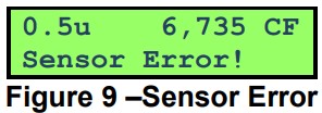 4.3. Sampling
The following sub-sections cover sample related functions.
4.3.1. Starting/Stopping
Press the START/STOP key to start or stop a sample from the Sample Screen.
Depending on the sample mode, the unit will either run a single sample or continuous samples. Sample modes are discussed in Section 4.3.2.
4.3.2. Sample Mode
The sample mode controls single or continuous sampling. The Manual setting configures the unit for a single sample. The Continuous setting configures the unit for nonstop sampling.
4.3.3. Count Units
The 804 supports total counts (TC), particles per cubic foot (CF) and particles per liter (/L). Concentration values (CF, /L) are time dependent. These values may fluctuate early in the sample; however, after several seconds the measurement will stabilize.
Longer samples (e.g. 60 seconds) will improve concentration measurement accuracy.
4.3.4. Sample Time
Sample time determines the sample duration. Sample time is user settable from 3 to 60 seconds and is discussed in Sample Timing below.
4.3.5. Hold Time
The hold time is used when Samples is set for more than one sample. The hold time represents the time from the completion of the last sample to the start of the next sample. The hold time is user settable from 0 – 9999 seconds.
4.3.6. Sample Timing
The following figures depict the sample timing sequence for both manual and continuous sampling. Figure 10 shows the timing for manual sample mode. Figure 11shows the timing for continuous sample mode. The Start section includes a 3 second purge time.
Use the Settings Menu to view or change configuration options.
5.1. View Settings
Press the Select dial to navigate to the Settings Menu. Rotate the Select dial to scroll through the settings in the following table. To return to the Sample screen, press Start/Stop or wait 7 seconds.
The Settings menu contains the following items.
| Function | Description |
| LOCATION | Assign a unique number to a location or area. Range = 1 – 999 |
| SIZES | The 804 has four (4) programmable count channels. The operator can assign one of seven preset sizes to each count channel. Standard sizes: 0.3, 0.5, 0.7, 1.0, 2.5, 5.0, 10. |
| FAVORITES | This feature eliminates the need to scroll the display when monitoring two non-adjacent sizes. See Section 4.2.1. |
| MODE | Manual or Continuous. The Manual setting configures the unit for a single sample. The Continuous setting configures the unit for nonstop sampling. |
| COUNT UNITS | Total Count (TC), Particles / cubic foot (CF), particles / L (/L). See Section 4.3.3. |
| HISTORY | Display previous samples. See Section 5.1.1 |
| SAMPLE TIME | See Section 4.3.4. Range = 3 – 60 seconds |
| HOLD TIME | See Section 4.3.5. Range 0 – 9999 seconds |
| TIME | Display / enter time. Time format is HH:MM:SS (HH = Hours, MM = Minutes, SS = Seconds). |
| DATE | Display / enter date. Date format is DD/MMM/YYY (DD = Day, MMM = Month, YYYY = Year) |
| FREE MEMORY | Display the percentage of memory space which is available for data storage. When Free Memory = 0%, the oldest data will be overwritten with new data. |
| PASSWORD | Enter a four (4) digit numeric number to prevent unauthorized changes to the user settings. |
| ABOUT | Display model number and firmware version |
5.1.1. View Sample History
Press the Select dial to navigate to the Settings Menu. Rotate the Select dial to the History selection. Follow the steps below to view sample history. To return to the Settings Menu, press Start/Stop or wait 7 seconds.
| Press to View HISTORY |
Press Select to view history. |
| 30/MAR/2011 L001 10:30:45 #2500 |
804 will display the last record (Date, Time, Location, and Record Number). Rotate dial to scroll through records. Press to view record. |
| 0.3u 2,889 CF 0.5u 997 60 5.0u 15 60 10u 5 60 Location 001 DATE 30/MAR/2011 TIME 10:30:45 Low Battery! |
Rotate dial to scroll through record data (counts, date, time, alarms). Press Start/Stop to return to previous screen. |
5.2. Edit Settings
Press the Select dial to navigate to the Settings Menu. Rotate the Select dial to scroll to the desired setting then press the Select dial to edit the Setting. A blinking cursor will indicate edit mode. To cancel edit mode and return to the Settings Menu, press Start/Stop.
Edit mode is disabled when the 804 is sampling (see below).
| Sampling… Press Stop Key |
Screen displayed for 3 seconds then return to Settings Menu |
5.2.1. Password Feature
The following screen is displayed if you attempt to edit a setting when the password feature is enabled. The unit will remain unlocked for a period of 5 minutes after a successful password unlock code is entered.
| Press to Enter UNLOCK #### |
Press Select to enter Edit mode. Return to Sample screen if no Select key in 3 seconds |
| Rotate and Press UNLOCK 0### |
Blinking cursor indicates Edit mode. Rotate dial to scroll value. Press dial to select next value. Repeat action until last digit. |
| Rotate and Press UNLOCK 0001 |
Rotate dial to scroll value. Press dial to exit Edit Mode. |
| Incorrect Password! |
Screen displayed for 3 seconds if the password is incorrect. |
5.2.2. Edit Location Number
| Press to Change LOCATION 001 |
View screen. Press Select to enter Edit mode. |
| Rotate and PressLOCATION 001 | Blinking cursor indicates Edit mode. Rotate dial to scroll value. Press dial to select next value. Repeat action until last digit. |
| Rotate and Press LOCATION 001 |
Rotate dial to scroll value. Press dial to exit Edit Mode and return to view screen. |
5.2.3. Edit Sizes
| Press to View CHANNEL SIZES |
Press Select to view Sizes. |
| Press to Change SIZE 1 of 4 0.3µ | Sizes view screen. Rotate dial to view channel sizes. Press dial to change setting. |
| Rotate and Press SIZE 1 of 4 0.5µ |
Blinking cursor indicates Edit mode. Rotate dial to scroll values. Press dial to exit Edit mode and return to view screen. |
5.2.4. Edit Favorites
| Press to View FAVORITES | Press Select to view Favorites. |
| Press to Change FAVORITE 1 0.3µ |
Favorites view screen. Rotate dial to view Favorite 1 or Favorite 2. Press dial to change setting. |
| Rotate and Press FAVORITE 1 0.3µ |
Blinking cursor indicates Edit mode. Rotate dial to scroll value. Press dial to exit Edit mode. Return to view screen. |
5.2.5. Edit Sample Mode
| Press to Change MODE CONTINUOUS |
View screen. Press Select to enter edit mode. |
| Rotate and Press MODE CONTINUOUS |
Blinking cursor indicates Edit mode. Rotate dial to toggle value. Press dial to exit Edit mode and return to view screen. |
5.2.6. Edit Count Units
| Press to Change COUNT UNITS CF |
View screen. Press Select to enter edit mode. |
| Rotate and Press COUNT UNITS CF |
Blinking cursor indicates Edit mode. Rotate dial to toggle value. Press dial to exit Edit mode and return to view screen. |
5.2.7. Edit Sample Time
| Press to Change SAMPLE TIME 60 |
View screen. Press Select to enter Edit mode. |
| Rotate and Press SAMPLE TIME 60 |
Blinking cursor indicates Edit mode. Rotate dial to scroll value. Press dial to select next value. |
| Rotate and Press SAMPLE TIME 10 |
Rotate dial to scroll value. Press dial to exit Edit Mode and return to view screen. |
5.2.8. Edit Hold Time
| Press to change HOLD TIME 0000 |
View screen. Press Select to enter Edit mode. |
| Press to change HOLD TIME 0000 |
Blinking cursor indicates Edit mode. Rotate dial to scroll value. Press dial to select next value. Repeat action until last digit. |
5.2.9. Edit Time
| Press to Change TIME 10:30:45 |
View screen. Time is real time. Press Select to enter edit mode. |
| Rotate and Press TIME 10:30:45 |
Blinking cursor indicates Edit mode. Rotate dial to scroll values. Press dial to select next value. Repeat action until last digit. |
| Rotate and Press TIME 10:30:45 |
Last digit. Rotate dial to scroll values. Press dial to exit Edit mode and return to view screen. |
5.2.10.Edit Date
| Press to Change DATE 30/MAR/2011 |
View screen. Date is real time. Press Select to enter edit mode. |
| Rotate and Press DATE 30/MAR/2011 |
Blinking cursor indicates Edit mode. Rotate dial to scroll values. Press dial to select next value. Repeat action until last digit. |
| Rotate and Press DATE 30/MAR/2011 |
Rotate dial to scroll values. Press dial to exit Edit mode and return to view screen. |
5.2.11. Clear Memory
| Press to Change FREE MEMORY 80% |
View screen. Available memory. Press Select to enter edit mode. |
| Press and Hold to Clear Memory |
Hold Select dial for 3 seconds to clear memory and return to view screen. Return to view screen if no action for 3 seconds or key hold time is less than 3 seconds. |
5.2.12. Edit Password
| Press to Change PASSWORD NONE |
View screen. #### = Hidden password. Press Select to enter Edit mode. Enter 0000 to disable password (0000 = NONE). |
| Rotate and Press PASSWORD 0000 |
Blinking cursor indicates Edit mode. Rotate dial to scroll value. Press dial to select next value. Repeat action until last digit. |
| Rotate and Press PASSWORD 0001 |
Rotate dial to scroll value. Press dial to exit Edit Mode and return to view screen. |
Serial Communications
Serial communications, firmware field upgrades and real time output are provided via the USB port located on the side of the unit.
6.1. Connection
ATTENTION:
The included USB driver must be installed before connecting the 804 USB port to your computer. If the supplied drivers are not installed first, Windows may install generic drivers that are not compatible with this product.
To install USB drivers:
Follow the USB Drivers instructions on the included software placard.
Note: For proper communication, set the virtual COM port baud rate to 38400
6.2. Commands
The 804 provides serial commands for accessing stored data and settings. The protocol is compatible with terminal programs such as Windows HyperTerminal.
The unit returns a prompt (‘*’) when it receives a carriage return to indicate a good connection. The following table lists the available commands and descriptions.
| SERIAL COMMANDS | ||
| Protocol Summary: · 38,400 Baud, 8 Data bits, No Parity, 1 Stop Bit · Commands (CMD) are UPPER or lower case · Commands are terminated with a carriage return <CR> · To view setting = CMD <CR> · To change setting = CMD <SPACE> <Value> <CR> |
||
| CMD | Type | DESCRIPTION |
| ?,H | Help | View the help menu |
| 1 | Settings | View the settings |
| 2 | All data | Returns all available records. |
| 3 | New data | Returns all records since last ‘2’ or ‘3’ command. |
| 4 | Last data | Returns the last record or last n records (n = <Value>) |
| D | Date | Change date. Date is format is MM/DD/YY |
| T | Time | Change time. Time format is HH:MM:SS |
| C | Clear data | Displays a prompt for clearing the stored unit data. |
| S | Start | Start a sample |
| E | End | Ends a sample (abort the sample, no data record) |
| SH | Hold Time | Get/Set the hold time. Range 0 – 9999 seconds. |
| ST | Sample time | View / change the sample time. Range 3-60 seconds. |
| ID | Location | View / change the location number. Range 1-999. |
| CS wxyz | Channel Sizes | View / change channel sizes where w=Size1, x=Size2, y=Size3 and z=Size4. Values (w x y z) are 1=0.3, 2=0.5, 3=0.7, 4=1.0, 5=2.5, 6=5.0, 7=10 |
| SM | Sample mode | View / change sample mode. (0=Manual, 1= Continuous) |
| CU | Count units | View / change count units. Values are 0=CF, 1=/L,2=TC |
| OP | Op Status | Replies OP x, where x is “S” Stopped or “R” Running |
| RV | Revision | View Software Revision |
| DT | Date Time | View / change date and time. Format = DD-MM-YY HH:MM:SS |
6.3. Real Time Output
The Model 804 outputs real time data at the end of each sample. The output format is a comma separated values (CSV). The following sections show the format.
6.4. Comma Separated Value (CSV)
A CSV header is included for multiple record transfers like Display All Data (2) or Display New Data (3).
CSV Header:
Time, Location, Period, Size1, Count1, Size2, Count2, Size3, Count3, Size4, Count4, Units, Status
CSV Example Record:
31/AUG/2010 14:12:21,
001,060,0.3,12345,0.5,12345,5.0,12345,10,12345,CF,000<CR><LF>
Note: Status bits: 000 = Normal, 016 = Low Battery, 032 = Sensor Error, 048 = Low battery and Sensor Error.
Maintenance
WARNING: There are no user serviceable components inside this instrument. The covers on this instrument should not be removed or opened for servicing, calibration or any other purpose except by a factory-authorized person. To do so may result in exposure to invisible laser radiation that can cause eye injury.
7.1. Charging the Battery
Caution:
The provided battery charger is designed to work safely with this device. Do not attempt to connect any other charger or adapter to this device. Doing so may result in equipment damage.
To charge the battery, connect the battery charger module AC power cord to an AC power outlet and the battery charger DC plug to the socket on the side of the 804. The universal battery charger will work with power line voltages of 100 to 240 volts, at 50/60 Hz. The battery charger LED indicator will be Red when charging and Green when fully charged. A discharged battery pack will take approximately 2.5 hours to fully charge.
There is no need to disconnect the charger between charging cycles because the charger enters a maintenance mode (trickle charge) when the battery is fully charged.
7.2. Service Schedule
Although there are no customer serviceable components, there are service items which ensure the proper operation of the instrument. Table 1 shows the recommended service schedule for the 804.
| Item To Service | Frequency | Done By |
| Flow rate test | Monthly | Customer or Factory Service |
| Zero test | Optional | Customer or Factory Service |
| Inspect pump | Yearly | Factory service only |
| Test battery pack | Yearly | Factory service only |
| Calibrate Sensor | Yearly | Factory service only |
Table 1 Service Schedule
7.2.1. Flow Rate Test
The sample flow rate is factory set to 0.1cfm (2.83 lpm). Continued use can cause minor changes in flow which can reduce measurement accuracy. A flow calibration kit is available separately that includes everything needed to test and adjust the flow rate.
To test the flow rate: remove the inlet screen holder. Attach the inlet adapter connected to the flow meter (MOI# 80530) to the instrument inlet. Start a sample, and note the flow meter reading. The flow rate should be 0.10 CFM (2.83 LPM) µ5%.
If the flow is not within this tolerance, it can be adjusted by a trim pot located in an access hole in the side of the unit. Turn the adjustment pot clockwise to increase the flow and counter-clockwise to decrease the flow.
- 7.2.1. Zero Count Test
The 804 automatically monitors system noise and displays a System Noise warning when the noise level is high (see Section 4.2.2). This diagnostic reduces the necessity for an inlet filter zero count test. However, a zero count kit can be purchased separately if desired.
7.2.2. Annual Calibration
The 804 should be sent back to Met One Instruments yearly for calibration and inspection. Particle counter calibration requires specialized equipment and training.
The Met One Instruments calibration facility uses industry accepted methods such as ISO and JIS.
In addition to calibration, the annual calibration includes the following preventative maintenance items to reduce unexpected failures: - Inspect filter
- Inspect / clean optical sensor
- Inspect pump and tubing
- Cycle and test the battery
7.3. Flash Upgrade
Firmware can be field upgraded via the USB port. Binary files and the flash program must be provided by Met One Instruments.
Troubleshooting
WARNING: There are no user serviceable components inside this instrument. The covers on this instrument should not be removed or opened for servicing, calibration or any other purpose except by a factory-authorized person. To do so may result in exposure to invisible laser radiation that can eye injury.
The following table covers some common failure symptoms, causes and solutions.
| Symptom | Possible Cause | Correction |
| Low battery message | Low battery | Charge battery 2.5 hrs |
| System noise message | Contamination | 1. Check inlet screen 2. Blow clean air into nozzle (low pressure, do not connect via tubing) 3. Send to service center |
| Sensor error message | Sensor failure | Send to service center |
| Does not turn on, no display | 1. Dead battery 2. Defective Battery |
1.Charge battery 2.5 hrs 2. Send to service center |
| Display turns on but pump does not | 1. Low Battery 2. Defective pump |
1.Charge battery 2.5 hrs 2. Send to service center |
| No counts | 1. Pump stopped 2. Laser diode bad |
1.Send to service center 2.Send to service center |
| Low counts | 1. Low flow rate 2. Inlet screen clogged |
1. Check flow rate 2. Check inlet screen |
| High counts | 1. High flow rate 2. Calibration |
1. Check flow rate 2. Send to service center |
| Battery pack does not hold a charge | 1. Defective battery pack 2. Defective charger module |
1. Send to service center 2.Replace charger |
Specifications
| Features: | |
| Size Range: | 0.3 to 10.0 microns |
| Count Channels: | 4 channels preset to 0.3, 0.5, 5.0 and 10.0 mm |
| Size Selections: | 0.3, 0.5, 0.7, 1.0, 2.5, 5.0 and 10.0 mm |
| Accuracy: | ± 10% to traceable standard |
| Concentration Limit: | 3,000,000 particles/ft |
| Flow Rate: | 0.1 CFM (2.83 L/min) |
| Sampling Mode: | Single or Continuous |
| Sampling Time: | 3 – 60 seconds |
| Data Storage: | 2500 records |
| Display: | 2 line by 16-character LCD |
| Keyboard: | 2 button with rotary dial |
| Status Indicators: | Low Battery |
| Calibration | NIST, JIS |
| Measurement: | |
| Method: | Light scatter |
| Light Source: | Laser Diode, 35 mW, 780 nm |
| Electrical: | |
| AC Adapter/Charger: | AC to DC module, 100 – 240 VAC to 8.4 VDC |
| Battery Type: | Li-ion rechargeable Battery |
| Battery Operating Time: | 8 hours continuous use |
| Battery Recharge Time: | 2.5 hours typical |
| Communication: | USB Mini B Type |
| Physical: | |
| Height: | 6.25” (15.9 cm) |
| Width: | 3.63” (9.22 cm) |
| Thickness: | 2.00” (5.08 cm) |
| Weight | 1.74 lbs – 28 ounces – (0.79 kg) |
| Environmental: | |
| Operating Temperature: | 0º C to +50º C |
| Storage Temperature: | -20º C to +60º C |
![]() Met One Instruments, Inc.
Met One Instruments, Inc.
1600 NW Washington Blvd.
Grants Pass, OR 97526
Telephone: 541-471-7111
Facsimile: 541-471-7116
metone.com
Model 804 Manual
804-9800 Rev H
Documents / Resources
 |
Met One 804 Handheld Particle Counter [pdf] Instruction Manual 804, 804 Handheld Particle Counter, 804, Handheld Particle Counter, Particle Counter, Counter |