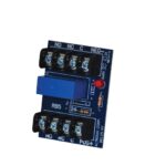
MEAN WELL DBUF40-24 24V/40A DIN Rail Type Buffer Module

Product Information
The DBUF40-24 is a 24V/40A DIN Rail Type Buffer Module. It is a supplementary device for regulated DC 24V power supplies. The buffer module utilizes maintenance-free electrolytic capacitors to store energy, eliminating the need for periodic replacement as compared to costlier batteries which also have a shorter functional lifespan. The DBUF40-24 comes with comprehensive protection features like overvoltage, overcurrent, and short circuit protections. Buffer modules can be connected in parallel to increase the output ampacity or the hold-up time.
Product Usage Instructions
To use the DBUF40-24 buffer module, follow these instructions:
- Ensure that the operating voltage of your DC power supply is within the range of 23-30Vdc.
- Connect the positive and negative terminals of the DC power supply to the corresponding terminals on the buffer module.
- If desired, connect multiple buffer modules in parallel to increase the output ampacity or hold-up time. Ensure that all modules are properly connected and within the specified voltage range.
- To enable buffering, set the voltage threshold by selecting one of the following options:
- Fix 22Vdc (default): Buffering starts if the terminal voltage falls below 22Vdc.
- Vin-1Vdc: Buffering starts if the terminal voltage is decreased by more than 1Vdc.
- To control the buffer module, use the following functions:
- Inhibit (I): Apply a voltage difference between +Vs and V(I) to turn the buffer module ON or OFF. If +Vs – V(I) is less than 6Vdc, the buffer module is ON. If +Vs – V(I) is greater than 10Vdc, the buffer module is OFF.
- Ready (R): Monitor the voltage level at V(R) to determine the status of the buffer module. If V(R) is greater than +Vs – 2Vdc, the module is charged and ready. If V(R) is less than +Vs – 2Vdc, the module is unready. Other mode conditions are indicated by the voltage level at V(B).
- Ensure that the buffer module is properly protected and meets safety standards. The module has overvoltage protection, overcurrent protection, short circuit protection, reverse polarity protection, and selectable switching options.
- Refer to the user manual for additional information on EMC emissions, EMC immunity, and other specifications.
Features
- Buffering with electrolytic capacitors instead of lead acid batteries
- Type buffering time of 250ms @22Vdc/40A
- Buffer mode selectable by switch: Fixed mode at 22Vdc Dynamic mode for Vin-1Vdc
- LED indicator for signal status
- Supports parallel connection to extend buffering time
- Cooling by free air convection
- -25~+75°C wide operating temperature
- 3 years warranty
Description
- The DBUF40-24 buffer module is a supplementary device for regulated DC 24V power supplies. The buffer module utilizes maintenance-free electrolytic capacitors to store energy, thus eliminates the need of periodic replacement as compared to costlier batteries which also have shorter functional life span.
- The DBUF40-24 comes with comprehensive protection features like over voltage, over current and short circuit protections. Buffer modules can be connected in parallel to increase the output ampacity or the hold – up time.
Model Encoding

Applications
- Industrial control system
- Semiconductor fabrication equipment
- Factory automation
- Electro-mechanical apparatus
GTIN CODE
MW Search: https://www.meanwell.com/serviceGTIN.aspx
SPECIFICATION
| MODEL | DBUF40-24 | |||||||
| CHARGING MODE | DC NORMAL OPERATING VOLTAGE | 24Vdc | ||||||
| CHARGING VOLTAGE | 23~30Vdc | |||||||
| CHARGING CURRENT | 900mA Max. | |||||||
| CURRENT CONSUMPTION AT STANDBY | 100mA Max. | |||||||
| CHARGING TIME | 25s Typ. | |||||||
| 35s Max. | ||||||||
| BUFFER MODE | DC NORMAL OPERATING VOLTAGE | 22Vdc/Vin-1Vdc | ||||||
| DC OPERATING VOLTAGE RANGE | 22-29Vdc | |||||||
| OUTPUT CURRENT(max.) | 40A | |||||||
| BUFFER TIME
(Refer to Buffering Curve at 22Vdc) |
Output current | 40A | 20A | 0.1A | ||||
| Typ. | 250ms | 500ms | 62s | |||||
| Min. | 160ms | 320ms | 42s | |||||
| RIPPLE & NOISE (max.) Note.2 | 350mVp-p | |||||||
| PROTECTION | OVER VOLTAGE | 31~37.5V only,shut down o/p voltage | ||||||
| OVER LOAD | 105%~125% rated output power at buffer mode | |||||||
| Protection type:Shut down o/p voltage , re-power on to recover | ||||||||
| SHORT CIRCUIT | Protection type:Shut down o/p voltage , re-power on to recover | |||||||
| TVS FOR SIGNALS (max.) | 35V | |||||||
| REVERSE POLARITY PROTECTION | By internal MOSFET, no damage , recovers automatically after fault condition removed | |||||||
| FUNCTION | SELECTABLE BY SWITCH | Fix 22Vdc(Default) | Buffering starts if terminal voltage falls below 22Vdc | |||||
| Vin-1Vdc | Buffering starts if terminal voltage is decreased by > 1Vdc | |||||||
| CONTROL | Inhibit (I) | +Vs – V(I) < 6Vdc: Buffer module ON; +Vs – V(I) >10Vdc: Buffer module OFF | ||||||
| 35Vdc /4mA Max. | ||||||||
| SIGNALS | Ready(R) | Charged ready: V(R)>+Vs – 2Vdc; Unready: V(R)<1Vdc | ||||||
| 35Vdc /10mA Max. | ||||||||
| Buffering (B) | Buffering: V(B)>+Vs – 2Vdc; Other mode: V(B)<1Vdc | |||||||
| 35Vdc /10mA Max. | ||||||||
| Supply Voltage(+Vs) | 10~35Vdc /10mA(Connected to +V or external voltage) | |||||||
| LED STATUS DISPLAY | ON | Ready | ||||||
| OFF | Discharged | |||||||
| Flashing | 1Hz | Charging | ||||||
| 10Hz | Buffering | |||||||
| PARALLEL CONNECTION | Refer to Typical Application Notes(Page 6) | |||||||
| ENVIRONMENT | WORKING TEMP. | -25~+75℃(Refer to”Derating Curve”) | ||
| WORKING HUMIDITY | 5 ~ 95% RH non-condensing | |||
| STORAGE TEMP. | -25~+80℃ | |||
| SHOCK TEST | IEC60068-2-27,30G (300m/S²) for a duration of 18ms,1 time per direction,2 times in total | |||
| TEMP. COEFFICIENT | ±0.03%/℃ (0 ~ 75℃) | |||
| VIBRATION | Component: 10 ~ 500Hz, 2G 10min./1cycle, 60min. each along X, Y, Z axes; Mounting clip: Compliance to IEC60068-2-6 | |||
| OPERATING ALTITUDE Note.3 | 5000 meters /OVCⅡ | |||
| SAFETY & EMC (Note.4) | SAFETY STANDARDS | IEC62368-1,UL62368-1 approved | ||
| WITHSTAND VOLTAGE | IP/OP-FG:2.2KVdc; Signals-FG:2.2KVdc | |||
| ISOLATION RESISTANCE | IP/OP-FG, Signals-FG: >100M Ohms / 500Vdc / 25℃/ 70% RH | |||
| EMC EMISSION | Parameter | Standard | Test Level / Note | |
| Conducted | BS EN/EN55032 | Class B | ||
| Radiated | BS EN/EN55032 | Class B | ||
| Voltage Flicker | —– | —– | ||
| Harmonic Current | —– | —– | ||
| EMC IMMUNITY | BS EN/EN55035, BS EN/EN61000-6-2 | |||
| Parameter | Standard | Test Level / Note | ||
| ESD | BS EN/EN61000-4-2 | Level 4, 15KV air ; Level 3, 8KV contact; criteria A | ||
| Radiated | BS EN/EN61000-4-3 | Level 3, 10V/m ; criteria A | ||
| EFT / Burst | BS EN/EN61000-4-4 | Level 3, 2KV ; criteria A | ||
| Surge | BS EN/EN61000-4-5 | Level 3, 1KV/Line-Line ;Level 3, 2KV/Line-Line-FG ;criteria A | ||
| Conducted | BS EN/EN61000-4-6 | Level 3, 10V ; criteria A | ||
| Magnetic Field | BS EN/EN61000-4-8 | Level 4, 30A/m ; criteria A | ||
| OTHERS | MTBF | 162.6K hrs min. MIL-HDBK-217F (25℃) ; 1420.2K hrs min. Telcordia TR/SR-332 (Bellcore) (25℃) | ||
| 106.8K hrs min. MIL-HDBK-217F (40℃) ; 717.2K hrs min. Telcordia TR/SR-332 (Bellcore) (40℃) | ||||
| DIMENSION | 63*125.2*114.9mm (W*H*D) | |||
| PACKING | 1.062Kg; 12pcs/12.8Kg/0.74CUFT | |||
| NOTE |
For guidance on how to perform these MC tests, please refer to “EMI testing of component power supplies.” (as available on http://www.meanwell.com) ⅚ Product Liability Disclaimer: For detailed information, please refer to https://www.meanwell.com/serviceDisclaimer.aspx |
|||
Block Diagram

Derating Curve

Buffering Curve Function Manual
user Elements

- Back-up Threshold Voltage Selectable by Switch:
- Option 1: Fixed mode (Switch in Fix 22Vdc) The unit switches to buffer mode as soon as the voltage falls below 22Vdc.
- Option 2: Dynamic mode (Switch in Vin-1Vdc) Unit switches to buffer mode when input voltage decreases by 1Vdc.
- Note: Factory setting is fixed mode.
- LED Indicator Status:
- LED OFF: Capacitors are discharged.
- LED ON: Capacitors are fully charged.
- LED Flashing slowly (1Hz): Capacitors are getting charged.
- LED Flashing quickly (10Hz): Capacitors are getting discharged.
- Signal Connector:
- Inhibit, +Vs – V(1)<6Vdc:
- Buffer module ON; +Vs -V(I)>10Vdc:
- Buffer module OFF.
- Ready, Charged ready: V(R)>+Vs – 2Vdc; Unready: V(R)<1Vdc.
- Buffering, Buffering: V(B)>+Vs – 2Vdc; Other mode: V(B)<1Vdc.
- Inhibit, +Vs – V(1)<6Vdc:
Operating Diagram
 Signal Schematics

Typical Application Notes
- General wiring diagram

- Signals supplied from an external voltage

- Paralleling of buffer units

Mechanical Specification
Terminal Pin No. Assignment (TB 1)
| Pin No. | Assignment |
| 1,2 | DC +V |
| 3,4 | DC -V |


Terminal Pin No. Assianment (TB2)
| Pin No. | Assignment |
| 1 | FG |
| 2 | Inhibit (I) |
| 3 | Ready (R) |
| 4 | Buffering (B) |
| 5 | Supply Voltage (+Vs) |

Installation Instruction

- This series fits DIN rail TS35/7.5 or TS35/15. For installation details, please refer to the Instruction manual.
- ADMISSIBLE DIN-RAIL:TS35/7.5 or TS35/15 (For reference only. Not included with unit.)
Installation Manual Please refer to : http://www.meanwell.com/manual.html
Documents / Resources
 |
MEAN WELL DBUF40-24 24V/40A DIN Rail Type Buffer Module [pdf] Owner's Manual DBUF40-24 24V 40A DIN Rail Type Buffer Module, DBUF40-24 24V, 40A DIN Rail Type Buffer Module, Type Buffer Module, Buffer Module, Module |