![]() AUTOMATIC MULTIMETER
AUTOMATIC MULTIMETER
WITH COLOR DISPLAY – 3″ Product code
25 703
User Manual
![]()
Contents
hide
General description
The advantage of the fully automatic multimeter is that during the measurement, the device automatically recognizes which function is needed and performs the measurement in that function. The measurement results can be easily and quickly read from the large color display.
With the help of the sensor on the back of the device, you can detect voltage without breaking the wiring. It is equipped with a „fuse blown” indication, as well as a light for the test lead socket, which shows the correct connection method for different measurements. It is characterized by an ergonomic device housing, compact size and easy handling. The practical, hard-walled carrier bag protects the product during transport.
With the help of the sensor on the back of the device, you can detect voltage without breaking the wiring. It is equipped with a „fuse blown” indication, as well as a light for the test lead socket, which shows the correct connection method for different measurements. It is characterized by an ergonomic device housing, compact size and easy handling. The practical, hard-walled carrier bag protects the product during transport.
- Large, color display
- Automatic measurement function setting
- Possibility of manual setting
- Continuity test
- Resistance measurement
- Voltage measurement
- Current measurement
- Frequency measurement/Duty cycle
- Diode test
- Temperature measurement
- Capacity measurement
- Phase detection and non-contact voltage detection
- Flashlight function
- Sound and light signal
- Data hold
- Automatic shutdown
- Accessories: Test leads, thermometer probe, carrying case
Safety information
- Before use, make sure that all accessories are in the package and undamaged. The meter is designed in accordance with IEC61010 (safety standard issued by the International Electrotechnical Commission or equivalent GB4793.1). Please read the safety notes before use.
- Only take measurements in the measuring range! Do not use in a larger range!
- If you measure voltage higher than 36 V DC or 25 V AC, check the connection and insulation of the test leads to avoid electric shock.
- When changing the measurement mode (functions) and range, the measuring tips must be removed from the test point.
- Before measuring, always make sure that you are measuring a voltage that corresponds to the measurement limit.
- Before changing batteries or fuses, always remove the measuring tips from the measuring point and switch off the device.
- Do not operate the device if the battery or battery cover is not properly attached!
-
Only measure capacitance, diode or continuity on a deenergized circuit
-
Please comply with the local and national safety regulations: During the measurement, if necessary, wear personal protective equipment (gloves, face mask, flame-resistant clothing) to avoid injuries from electric shock and arcing.
-
Only measure according to the appropriate Standard Measurement Category (CAT). (voltage probe, test lead and adapter)
General Maintenance and warnings
The instrument is a precision designed product, it is forbidden to modify its circuit in any way!
- Please make sure that the instrument is not exposed to water, dust or dropped!
- Do not store and use the instrument at high temperatures and humidity, as well as near flammable and explosive materials and in strong magnetic fields! Do not expose the device to large temperature fluctuations!
- To clean it, use a damp cloth, do not use scouring agents, alcohol or other organic solvents!
- The device can only be used by adults, the storage location must be chosen in such a way that children cannot accidentally access it. Children must not play with the device.
- The device is designed for residential use!
- The device may only be used by persons who have read and understood this user manual and are able to operate the device accordingly! Persons with reduced mental, physical or sensory abilities may not use the device! Children must not use the device!
- The manufacturer and distributor do not assume responsibility for injuries and damages resulting from improper use!
- In any case, check that the device, cable, connector and accessories are intact! Do not use the device if it is damaged!
usage
Operation and Functions
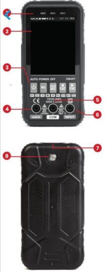
- Light signal
- LCD Display 2×4 digit (5x6cm)
- Power and function buttons
- Current measuring socket
- COM measurement plug
- INPUT measurement plug
- Non-contact voltage test sensor
- Work light
Display and symbols
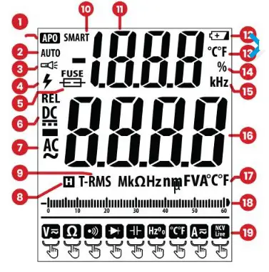
- Automatic shutdown
- Automatic measurement limit
- Work light
- High voltage warning
- Fuse error
- Direct current and voltage
- Alternating current and voltage
- Date hold function
- True RMS measurement
- SMART – automatic mode
- Secondary display
- Drained battery
- Temperature measurement
- Duty cycle measurement
- Frequency measurement
- Main display
- Unit
- Function measurement limit display
- Functions
Switc hing on and off
Long press the power button
Modes
Automatic measurement mode:
When switched on, this measurement mode is the default.
In this mode, AC/DC voltage and current, resistance and continuity can be measured and the instrument automatically identifies the signal to be measured. Press the button to turn on, the instrument will show „Auto” in intelligent measurement mode. Connect the red banana plug to the “INPUT” jack and the black banana plug to the “COM” jack. Touch the measuring tips parallel to the unit to be measured and the device will automatically recognize the measured signal. Read the measurement results from the display. During resistance measuring, if the resistance value is less than about 50 Ω, the device signals with a sound and light signal. When measuring current, move the red banana plug to the „mA/A” socket, the instrument will automatically switch to the current measurement function.
NOTE: In this mode, the minimum measurable voltage is 0,8 V
Manual measurement mode:
NOTE: In this mode, the minimum measurable voltage is 0,8 V
Manual measurement mode:
After switching on, the instrument is in automatic measurement mode, you can manually switch between modes by pressing the „FUNC” function buttons. The characters on the display indicate the current operating mode, and lighting at the sockets shows the location of the test leads. To switch back to automatic mode, press and hold any “FUNC” button.
Voltage measurement:
Select the voltage measurement function „V”, then press the „SEL” button to select the voltage type (AC – Alternating, DC – Direct)
Connect the red banana plug to the “INPUT” jack and the black banana plug to the “COM” jack. Touch the probes to the circuit to be measured. The measured value appears on the display.
Resistance measurement:
Select the resistance measurement function “Ω”. Connect the red banana plug to the “INPUT” jack and the black banana plug to the “COM” jack. Touch the probes to the circuit to be measured. The measured value appears on the display. During measurement, the circuit must be free of voltage, check this in every case.
Tensile test:
Tensile test:
Select the tear test function “ Connect the red banana plug to the “INPUT” jack and the black banana plug to the “COM” jack. Touch the probes to the circuit to be measured. The measured resistance value appears on the display, if it is below 50 Ω, the instrument emits a beeping sound and the indicator LED lights up. During measurement, the circuit must be free of voltage, check this in every case.
Diode test:
Select the diode test function  „ Connect the red banana plug to the “INPUT” jack and the black banana plug to the “COM” jack. Touch the test tips to the diode to be tested, red is the anode, black is the cathode when measuring in the open direction. The displayed value is the forward voltage of the diode. In the event of a break or closing direction, „OL” appears on the display.
Capacity measurement:
Select the capacity measurement function  „ Connect the red banana plug to the “INPUT” jack and the black banana plug to the “COM” jack. Touch the probes to the circuit to be measured. Before measuring, the capacitors must be discharged in any case, in order to avoid the failure of the instrument. The instrument may need several seconds to measure larger capacity capacitors
Frequency and duty cycle measurement:
Select the frequency measurement function  „ Connect the red banana plug to the “INPUT” jack and the black banana plug to the “COM” jack. Touch the probes to the circuit to be measured. The measured value appears on the display, the lower line shows the frequency and the upper line shows the duty cycle.
Temperature measurement:
Temperature measurement:
Select the temperature measurement function „  . Connect the red banana plug of the test probe to the “INPUT” socket and the black banana plug to the “COM” socket. Touch the measuring tip to the surface to be measured. The measured value appears on the display, the bottom line shows °C (celsius) and the top one shows the temperature in °F (fahrenheit). Without connecting a measuring probe, the instrument shows the ambient temperature.
Current measurement:
Select the current measurement function „A”, then press the „SEL” button to select the type of current (AC converter, DC converter). Connect the red banana plug to the “mA/A” jack and the black banana plug to the “COM” jack. Touch the probes to the circuit to be measured. The measured value appears on the display. When measuring alternating current, the frequency of the measured current value is also displayed in the top row of the display.
Note: it is not possible to change the function from current measurement mode again until the „mA/A” the instrument cable is connected to the socket.
Data hold function:
During measurement, press the „HOLD” button, so the display keeps the measured value even after the measuring tips are removed. To deactivate the function, press the “HOLD” button again
Work light function:
Long press the “HOLD” button to turn on and off the work light on the back of the instrument.
Non-contact voltage detection and phase search function:
Select non-contact voltage detection and phase detection function „NCV/LIVE”
Select the desired function by pressing the SEL button.
NCV: For non-contact voltage detection, bring the sensor on the top of the instrument close to the wire to be measured, if the instrument is under voltage, it will be signaled by a beeping sound and LED indicators.
LIVE: For phase search, connect the red banana plug to the „INPUT” socket, then touch the probe to the circuit to be tested. If a phase is present, the instrument indicates it with a beeping sound and LED indicators
Properties:
| Display: | 3 5/6 digit (9999), 3″ LCD display |
| Power supply | 4x 1,5V AAA battery (included) |
| Operating temperature: | 0 – (+40) °C |
| Operating humidity: | 75% |
| DOC v: | 0.1 mv – 600 V |
| DCA | O.1mA-10A |
| ACV: | 0.1 mv – 600 V |
| ACA | O.1mA- 104 |
| Duty cycle: | 1% – 99% |
| Resistance: | 0.10-660MQ |
| Frequency: | 0.001 Hz – 10 MHz |
| Capacity | 1 pF – 69 mF |
| Temperature measurement: | 40 – (+1000) °C |
| Size: | 144x 73 x27 mm |
| Color: | Black |
Dc voltage(dcv)
| Measuring limit | Accuracy | Resolution |
| 600mV | ±(0.5% +3) | 0.1mV |
| 6V | 0.001V | |
| 60V | 0.01V | |
| 600V | 0.1V | |
| • Input impedance: 10MΩ • Maximum input voltage: ±600V |
||
Ac voltage (acv)
| Measuring limit | Accuracy | Resolution |
| 6V | ±(1.0%+3) | 0.001V |
| 60V | 0.01V | |
| 600V | 0.1V | |
|
Input impedance: 10MΩ
Maximum input voltage: ±600V
|
||
|
• Frequency range: 40Hz-1Khz, True RMS display
• Frequency measurement sensitivity: >1V
• Frequency measurement accuracy ±1%
|
||
Resistance(Ω)
| Measuring limit | Accuracy | Resolution |
| 600Ω | ±(1.0%+5) | 0.1Ω |
| 6KΩ | 0.001KΩ | |
| 60KΩ | 0.01KΩ | |
| 600KΩ | 0.1KΩ | |
| 6MΩ | 0.001MΩ | |
| 60MΩ | ±(2.0%+10) | 0.01MΩ |
| • Overvoltage protection: 250V | ||
Ac/Dc current (aca/dca)
| Measuring limit | Accuracy | Resolution |
| 600mA | ±(1.2%+3) | 0.1mA |
| 6A | 0.001A | |
| 10A | 0.01A | |
| • Overcurrent protection: F10A/250V fuse (5x20mm) | ||
| • Frequency range: 40Hz-1Khz, True RMS display • Frequency measurement sensitivity: >100mA • Frequency measurement accuracy ±1% |
||
Capacitance (f)
| Measuring limit | Accuracy | Resolution |
| 100 nF | ±(4.0%+5) | 0.001nF |
| 6nF | 0.01nF | |
| 60nF | 0.1nF | |
| 600nF | 0.001µF | |
| 6µF | 0.01µF | |
| 60µF | 0.1µF | |
| 600µF | ±(5.0%+5) | 0.001mF |
| 6mF | ±(10%+10) | 0.01mF |
| • Overvoltage protection: 250V | ||
Frequencyuty/d cycle (Hz/%)
| Measuring limit | Accuracy | Resolution |
| 6Hz | ±(1.0%+3) | 0.001Hz |
| 60Hz | 0.01Hz | |
| 600Hz | 0.1Hz | |
| 6KHz | 0.001KHz | |
| 60kHz | 0.01kHz | |
| 600kHz | 0.1kHz | |
| 6MHz | 0.001MHz | |
| 10MHz | 0.01MHz | |
| 1.0~99.0% | 0.10% | |
| • Overvoltage protection: 250V | ||
Temerature
| Unit | Resolution | Accuracy | |
| °C | 1 °C | -40~ 0 °C | ±3 °C |
| 0 ~ 1000 °C | ±2% or ±2 °C | ||
| °F | 1 °F |
-40~ 32 °F
|
±6 °F |
| 32~ 1832 °F | ±2% or ±4 °F | ||
Battery and fuse replacemen
- Remove the test leads from the instrument and the circuit under test.
- Remove the rubber protective cover
- Remove the battery cover screw and then remove the battery cover
- Replace the 4 AAA batteries or, if necessary, the fuse, with a value of 10A/250V, size 5×20 ceramic fuse
- Replace the battery holder, then the screw and rubber protective cover
![]() Proper disposal of the device (Electrical device) (Valid in the European Union and all other European states that participate in selective collection) According to the 2012/19/EU directives, electrical waste and devices cannot be thrown away as household waste. Old appliances must be collected in order to maximize the recycling of raw materials, thereby reducing their impact on people’s health and the environment. The crossed-out bin symbol is on all products for which separate collection is mandatory. Consumers should check with their local authorities for more information.
Proper disposal of the device (Electrical device) (Valid in the European Union and all other European states that participate in selective collection) According to the 2012/19/EU directives, electrical waste and devices cannot be thrown away as household waste. Old appliances must be collected in order to maximize the recycling of raw materials, thereby reducing their impact on people’s health and the environment. The crossed-out bin symbol is on all products for which separate collection is mandatory. Consumers should check with their local authorities for more information.
Documents / Resources
 |
MAXWELL 25703 Automatic Multimeter with Color Display [pdf] User Manual 25703, 923E, 25703 Automatic Multimeter with Color Display, 25703, Automatic Multimeter with Color Display, Multimeter with Color Display, Color Display, Display |
 |
MAXWELL 25703 Automatic Multimeter With Color Display [pdf] User Manual 25703 Automatic Multimeter With Color Display, 25703, Automatic Multimeter With Color Display, Multimeter With Color Display, With Color Display, Color Display, Display |