MAKE NOISE Maths Complex Function Generator Eurorack Module
Specifications
- Product Name: MATHS
- Type: Analog Computer for Musical Purposes
- Functions: Voltage Controlled Envelope, LFO, Signal Processing, Signal Generation
- Input Range: +/-10V
Product Usage Instructions
Installation
Before installation, refer to your case manufacturer’s specification for the location of the negative supply. Ensure proper power connection.
Overview
MATHS is designed for musical purposes and offers various functions including generating functions, integrating signals, amplifying, attenuating, inverting signals, and more.
Panel Controls
- Signal Input: Use for Lag, Portamento, and ASR envelopes. Range +/-10V.
- Trigger Input: The gate or Pulse triggers the circuit to generate Envelopes, Pulse Delay, Clock Division, and LFO Reset.
Rise, Fall, and Vari-Response
- The Rise, Fall, and Vari-Response parameters define the characteristics of the Envelope generated by the Trigger Input.
Signal Outputs
- The product offers various signal outputs including Envelopes, Clock Divisions, and more. Refer to the manual for detailed patch ideas.
Tips & Tricks
- Explore combining different control signals to create complex modulations. Experiment with modulating voltages and generating musical events based on motion sensing within the system.
Patch Ideas
- Refer to the manual for creative ways to patch MATHS with other modules in your system for unique sound generation and modulation possibilities.
INSTALLATION
Electrocution hazard!
- Always turn the Eurorack case off and unplug the power cord before plugging or unplugging any Eurorack bus board connection cable. Do not touch any electrical terminals when attaching any Eurorack bus board cable.
- The Make Noise MATHS is an electronic music module requiring 60mA of +12VDC and 50mA of -12VDC regulated voltage and a properly formatted distribution receptacle to operate. It must be properly installed into a Eurorack format modular synthesizer system case.
- Go to http://www.makenoisemusic.com/ for examples of Eurorack Systems and Cases.
- To install, find 20HP in your Eurorack synthesizer case, confirm proper installation of the Eurorack bus board connector cable on the backside of a module (see picture below), and plug the bus board connector cable into the Eurorack style bus board, minding the polarity so that the RED stripe on the cable is oriented to the NEGATIVE 12 Volt line on both the module and the bus board.
- On the Make Noise 6U or 3U Busboard, the negative 12 Volt line is indicated by the white stripe.
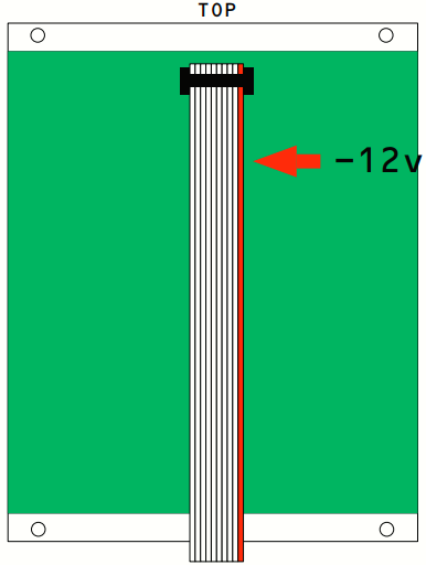
- Please refer to your case manufacturer’s specification for the location of the negative supply.
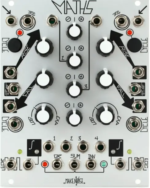
OVERVIEW
MATHS is an analog computer designed for musical purposes. Amongst other things, it allows you to:
- Generate a variety of linear, logarithmic, or exponential triggered or continuous functions.
- Integrate an incoming signal.
- Amplify, attenuate, and Invert an incoming signal.
- Add, subtract, and OR up to 4 signals.
- Generate analog signals from digital information (Gate/Clock).
- Generate digital information (Gate/Clock) from analog signals.
- Delay digital (Gate/Clock) information.
If the above list reads like science rather than music, here is the translation:
- Voltage Controlled Envelope or LFO as slow as 25 minutes and as fast as 1khz.
- Apply Lag, Slew, or Portamento to control voltages.
- Change the depth of modulation and modulate backward!
- Combine up to 4 control signals to create more complex modulations.
- Musical Events such as Ramping up or Down in Tempo, on command.
- Initiating Musical events upon sensing motion in the system.
- Musical note division and/or Flam.
MATHS revision 2013 is a direct descendant of the original MATHS, sharing the same core circuit and generating all the fantastic control signals that the original was capable of generating, but with some upgrades, additions, and evolutions.
- The layout of the controls has been changed to be more intuitive and to work more ?fluidly with the CV Bus and existing modules in our system such as the DPO, MMG, and ECHOPHON.
- The LED indication for signals has been upgraded to show both positive and negative voltages as well as to increase the display resolution. Even small voltages are readable on these LEDs.
- As Make Noise now offers a Multiple the Signal Output Multiple (from the original MATHS) has been changed to a Unity Signal Output. It allows for creating two variations of output, one at unity and the other as processed through the Attenuverter. Also allows for ease in patching function responses not possible with the Vari-Response control alone (see pg. 13).
- An Inverted SUM Output has been added for greater modulation possibilities.
- LED indication for the Sum Bus has been added for increased signal awareness.
- LED indication was added to show the state of the End Of Rise and End Of Cycle.
- End-of-Cycle Output is now buffered for improved circuit stability.
- Added reverse power protection.
- Added +/-10V offset range. The user has a choice of +/-10V offset at CH. 2 or +/-5V offset at CH. 3.
- Added greater Logarithmic range in Vari-Response control allowing for East Coast style Portamen-to.
- The evolution in the circuit is the Cycle Input which allows for voltage control of the Cycle state in Channels 1 and 4. On Gate High, the MATHS Cycles. On Gate low, MATHS does not Cycle (unless the Cycle button is engaged).
PANEL CONTROLS
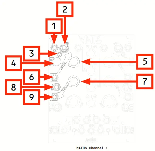
- Signal Input: Direct Coupled input to circuit. Use for Lag, Portamento, ASR (Attack Sustain Release type envelopes). Also, input to Sum/OR Bus. Range +/-10V.
- Trigger Input: A gate or Pulse applied to this input triggers the circuit regardless of the activity at the Signal Input. The result is a 0V to 10V function, aka Envelope, whose characteristics are defined by the Rise, Fall, and Vari-Response parameters. Use for Envelope, Pulse Delay, Clock Division, and LFO Reset (only during the Falling portion).
- Cycle LED: Indicates Cycle ON or OFF.
- Cycle Button: Causes the circuit to self-cycle, thus generating a repeating voltage function, aka LFO. Use for LFO, Clock, and VCO.
- Rise Panel Control: Sets the time it takes for the voltage function to ramp up. CW rotation increases Rise Time.
- Rise CV Input: Linear control signal input for Rise parameter. Positive Control signals increase Rise Time, and Negative control signals decrease Rise Time concerning the Rise panel control setting. Range +/-8V.
- Fall Panel Control: Sets the time it takes for the voltage function to ramp down. CW rotation increases Fall Time.
- Both CV Input: Bi-Polar Exponential control signal input for the entire function. Contrary to the Rise and Fall of CV Inputs, BOTH has an Exponential response and Positive control signals decrease total time while Negative control signals increase total time. Range +/-8V.
- Fall CV Input: Linear control signal input for Fall parameter. Positive control signals increase Fall time, and Negative control signals decrease Fall Time concerning the Fall panel control. Range +/-8V.
MATHS Channel 1
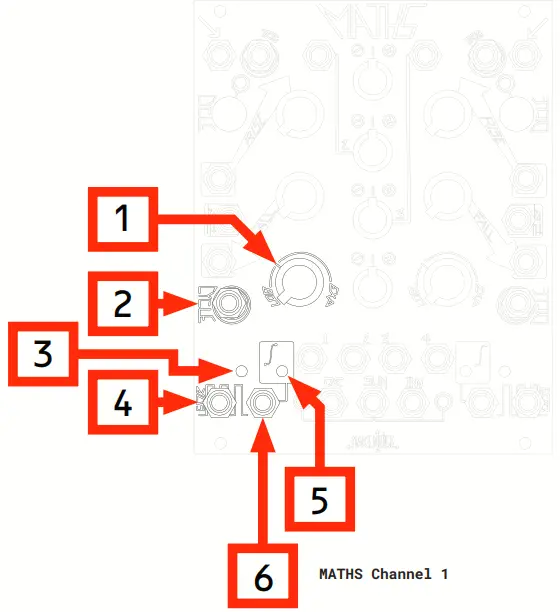
- Vari-Response Panel Control: Sets the response curve of the voltage function. The response is con-tinuously-variable from Logarithmic through Linear to Exponential to Hyper-Exponential. The Tick mark shows the Linear setting.
- Cycle Input: On Gate HIGH, Cycles on. On Gate LOW, MATHS does not Cycle (unless the Cycle button is engaged). Requires minimum +2.5V for HIGH.
- EOR LED: Indicates the states of the EOR Output. Lights when EOR is HIGH.
- End Of Rise Output (EOR): Goes high at the end of the Rise portion of the function. 0V or 10V.
- Unity LED: Indicates activity within the circuit. Positive voltages green, and negative voltages are red. Range +/-8V.
- Unity Signal Output: Signal from the Channel 1 circuit. 0-8V when Cycling. Otherwise, this output follows the amplitude of the input.
MATHS Channel 4
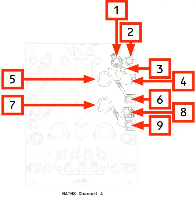
- Trigger Input: The gate or Pulse applied to this input triggers the circuit regardless of the activity at the Signal Input. The result is a 0V to 10V function, aka Envelope, whose characteristics are defined by the Rise, Fall, and Vari-Response parameters. Use for Envelope, Pulse Delay, Clock Division, and LFO Reset (only during the Falling portion).
- Signal Input: Direct Coupled input to circuit. Use for Lag, Portamento, ASR (Attack Sustain Release type envelopes). Also, input to Sum/OR Bus. Range +/-10V.
- Cycle LED: Indicates Cycle ON or OFF.
- Cycle Button: Causes the circuit to self-cycle, thus generating a repeating voltage function, aka LFO. Use for LFO, Clock, and VCO.
- Rise Panel Control: Sets the time it takes for the voltage function to ramp up. CW rotation increases Rise Time.
- Rise CV Input: Linear control signal input for Rise parameter. Positive Control signals increase Rise Time, and Negative control signals decrease Rise Time concerning the Rise panel control setting. Range +/-8V.
- Fall Panel Control: Sets the time it takes for the voltage function to ramp down. CW rotation increases Fall Time.
- Both CV Input: Bi-Polar Exponential control signal input for the entire function. Contrary to the Rise and Fall of CV Inputs, BOTH have an Exponential response and Positive control signals decrease total time while Negative control signals increase total time. Range +/-8V.
- Fall CV Input: Linear control signal input for Fall parameter. Positive control signals increase Fall time, and Negative control signals decrease Fall Time concerning the Fall panel control. Range +/-8V.
MATHS Channel 4
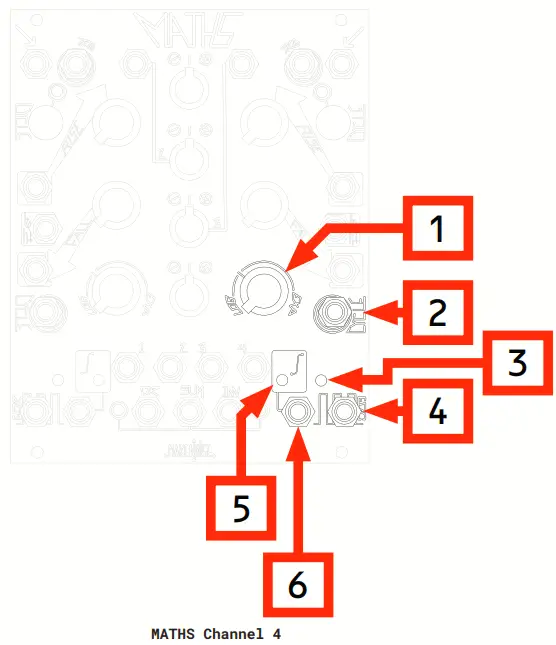
- Vari-Response Panel Control: Sets the response curve of the voltage function. The response is con-tinuously-variable from Logarithmic through Linear to Exponential to Hyper-Exponential. The Tick mark shows the Linear setting.
- Cycle Input: On Gate HIGH, Cycles on. On Gate LOW, MATHS does not Cycle (unless the Cycle button is engaged). Requires minimum +2.5V for HIGH.
- EOC LED: Indicates the states of the End of Cycle Output. Lights when EOC is High.
- End Cycle Output (EOC): Goes high at the end of the Fall portion of the function. 0V or 10V.
- Unity LED: Indicates activity within the circuit. Positive voltages green, and negative voltages are red. Range +/-8V.
- Unity Signal Output: Signal from the Channel 4 circuit. 0-8V when Cycling. Otherwise, this output follows the amplitude of the input.
SUM and OR Bus
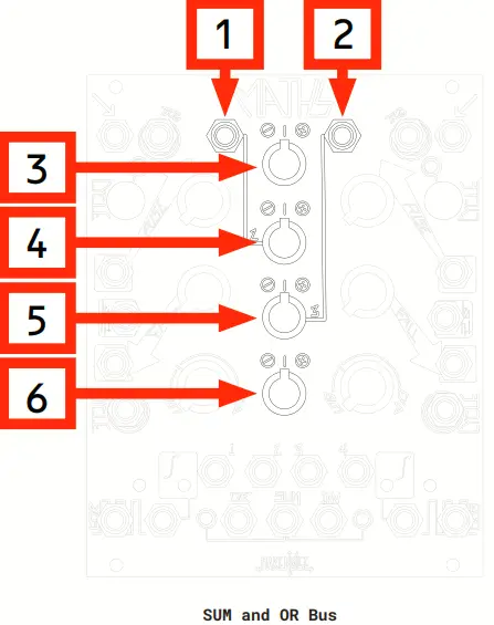
- Direct Coupled Channel 2 Signal Input: Normalized to a +10V reference for generation of voltage offsets. Input Range +/-10Vpp.
- Direct Coupled Channel 3 Signal Input: Normalized to a +5V reference for generation of voltage offsets. Input Range +/-10Vpp.
- CH. 1 Attenuverter Control: Provides for scaling, attenuation, and inversion of the signal being processed or generated by CH. 1. Connected to CH. 1 Variable Output and Sum/Or Bus.
- CH. 2 Attenuverter Control: Provides for scaling, attenuation, amplification, and inversion of signal patch to CH. 2 Signal Input. With no signal present, it controls the level of the set generated by CH. 2.
- Connected to CH. 2 Variable Output and Sum/OR Bus.
- CH. 3 Attenuverter Control: Provides for scaling, attenuation, amplification, and inversion of signal patch to CH. 3 Signal Input. With no signal present, it controls the level of the offset generated by CH. 3.
- Connected to CH. 3 Variable OUT and Sum/OR Bus.
- CH. 4 Attenuverter Control: Provides for scaling, attenuation, and inversion of the signal being processed or generated by CH. 4. Connected to CH. 4 Variable Output and Sum/OR Bus.
SUM and OR Bus
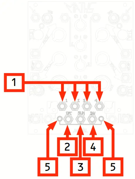
- CH. 1-4 Variable Outputs: The applied signal is processed by corresponding channel controls. Normalized to the SUM and OR busses. Inserting a patch cable removes the signal from the SUM and OR buses. Output Range +/-10V.
- OR Bus Output: Result of the Analog Logic OR function to the settings of the attenuverter controls for Channels 1, 2, 3, and 4. Range 0V to 10V.
- SUM Bus Output: Sum of the applied voltages to the settings of the attenuverter controls for Channels 1, 2, 3, and 4. Range +/-10V.
- Inverted SUM Output: Signal from SUM Output turned upside down. Range +/-10V.
- SUM Bus LEDs: Indicate voltage activity in the SUM bus (and therefore, the Inverted SUM as well). Red LED indicates negative voltages. Green LED indicates positive voltages.
GETTING STARTED
MATHS is laid out top to bottom, with symmetrical features between CH. 1 and 4. The signal inputs are at the top, followed by the panel controls and control signal inputs at the middle. The signal outputs are at the bottom of the module. LEDs are placed near the signal they are indicating. Channels 1 and 4 can scale, invert, or integrate an incoming signal. With no signal applied, these Chan-nels may be made to generate a variety of linear, logarithmic, or exponential functions upon the reception of a trigger, or continuously when the Cycle is engaged. One small difference between CH. 1 and 4 is in their respective Pulse Outputs; CH.1 having End of Rise and CH. 4 having End of Cycle. This was done to facilitate the creation of complex functions utilizing both CH. 1 and 4. Channels 2 and 3 can scale, amplify, and invert an incoming signal. With no external signal applied, these Channels generate DC offsets. The only difference between CH. 2 and 3 is that CH. 2 generates a +/-10V set while Ch. 3 generates a +/-5V offset.
All 4 Channels have outputs (called Variable Outputs) which are normalized to a SUM, Inverted SUM, and OR bus so that addition, subtraction, inversion, and analog logic OR manipulations may be achieved. Inserting a plug into these Variable Output sockets removes the associated signal from the SUM and OR bus (Channels 1 and 4 have unity outputs, which are NOT normalized to the SUM and OR bus). These outputs are controlled by the 4 Attenuverters at the center of the module.
Signal Input
These inputs are all directly coupled to their associated circuit. This means they can pass both audio and control signals. These inputs are used to process external control voltages. CH. 1 and 4 Signal Input could also be used to generate Attack/Sustain/ Release type envelopes from a gate signal. Channels 2 and 3 are also normalized to a voltage reference so that with nothing patched to the input, that channel could be used for the generation of voltage offsets. This is useful for level shifting a function or other signal that is at one of the other Channels by adding the voltage offset to that signal and taking the SUM Output.
Trigger Input
CH. 1 and 4 also have a Trigger input. A gate or pulse applied to this input triggers the associated circuit regardless of the activity at the Signal Inputs. The result is a 0V to 10V function, aka Envelope, whose characteristics are defined by the Rise, Fall, Vari-Response, and Attenuverter parameters. This function rises from 0V to 10V and then immediately falls from 10V to 0V. There is NO SUSTAIN. To get a sustaining envelope function, use the Signal Input (see above). MATHS re-triggers during the falling portion of the function but does NOT re-trigger on the rising portion of the function. This allows clock and gate division since MATHS could be programmed to ignore incoming clocks and gates by setting the Rise Time to be greater than the time between the incoming Clocks and/ or Gates.
Cycle
The Cycle Button and Cycle Input both do the same thing: they make MATHS self-oscillate aka Cycle, which are just fancy terms for an LFO! When you want an LFO, make MATHS Cycle.
RISE FALL VARI-RESPONSE
- These controls shape the signal that is output at the Unity Signal Output and Variable Outputs for CH. 1 and 4. The Rise and Fall controls determine how fast or slow the circuit responds to signals applied to the Signal Input and Trigger Input. The range of times is larger than the typical Envelope or LFO. MATHS creates functions as slow as 25 minutes (Rise and Fall full CW and external control signals added to go into “slow-ver-drive”) and as fast as 1khz (audio rate).
- Rise sets the amount of time the circuit takes to travel up to the maximum voltage. When triggered the circuit starts at 0V and travels up to 10V. Rise determines how long it takes for this to happen. When used to process external control voltages the signal applied to the Signal Input is either increasing, decreasing, or at a steady state (doing nothing). Rise determines how fast that signal could increase. One thing MATHS cannot do is look into the future to know where an external control signal is headed, therefore MATHS cannot increase the rate at which an external voltage changes/ moves, it can only act upon the present and slow it down (or allow it to pass at the same speed).
- Fall sets the amount of time the circuit takes to travel down to the minimum voltage. When triggered the voltage starts at 0V and travels up to 10V, at 10V the upper threshold is reached and the voltage begins to drop back down to 0V. Fall determines how long it takes for this to happen. When used to process external control voltages the signal applied to the Signal Input is either increasing, decreasing, or at a steady state (doing nothing). Fall determines how fast that signal could decrease. Since it cannot look into the future to know where an external control signal is headed, MATHS cannot increase the rate at which an external voltage changes/ moves, it can only act upon the present and slow it down (or allow it to pass at the same speed).
- Both Rise and Fall have independent CV inputs for voltage control over these parameters. If attenuation is required, use CH. 2 or CH. 3 in series to the desired destination. In addition to the Rise and Fall CV Inputs, there are also Both CV Inputs.
- Both CV input changes the rate of the entire function. It also responds inversely to the Rise and Fall of CV Inputs. More positive voltages make the entire function shorter and more negative voltages make the entire function longer.
- Vari-response shapes the above rates of change (Rise/Fall) to be Logarithmic, Linear, or Exponential (and everything in between these shapes).
- With the LOG response, the rate of change decreases as the voltage increases.
- With the EXPO response, the rate of change increases as the voltage increases. The Linear response has no change in rate as the voltage changes.
SIGNAL OUTPUTS
- There are many different signal outputs on the MATHS. All of them are situated at the bottom of the module. Many of them have LEDs situated nearby for visual indication of the signals.
The Variable Outs
- These outputs are labeled 1, 2, 3, and 4 and are associated with the four Attenuverter controls in the center of the module. These outputs are all determined by the settings of their associated controls, esp. the CH. 1 through 4 Attenuverter controls.
- All of these jacks are normalled to the SUM and OR Bus. With nothing patched to these outputs, the associated signal is injected into the SUM and OR Bus. When you patch a cable into any one of these output jacks, the associated signal is removed from the SUM and OR Bus. These outputs are useful when you have a modulation destination where there is no attenuation or inversion available (the CV inputs on the MATHS or FUNCTION modules for example).
- They are also useful when you want to create a variation of signal that is at a different amplitude or phase.
FOR OUT
- This is the End Of Rise Output for CH. 1. This is an event signal. It is either at 0V or 10V and nothing between. It defaults to 0V, or Low when there is no activity.
- The event in this case is when the associated Channel reaches the highest voltage to which it travels. This is a good signal to choose for Clocking or Pulse-shaped LFO.
- It is also useful for Pulse Delay and clock division since the Rise sets the amount of time it takes for this output to go High.
EOC OUT
- This is the End Cycle output for CH. 4. This is an event signal. It is either at 0V or 10V and nothing between. It defaults to +10V, or High when there is no activity.
- The event in this case is when the associated Channel reaches the lowest voltage to which it travels. The associated LED is on when nothing is happening. This is a good signal to choose for Clocking or Pulse-shaped LFO.
Unity Signal Outs (CH. 1 and 4)
- These outputs are tapped directly from the core of the associated Channel. They are not affected by the Channel’s Attenuverter.
- Patching into this output does NOT remove the signal from the SUM and OR Buses. This is a good output to use when you do not require attenuation or inversion or when you want to use the signal both independently and within the SUM/OR Bus.
OR OUT
- This is the output from the analog OR circuit. The inputs are CH. 1, 2, 3, and the 4 Variable Outputs. It always outputs the highest voltage out of all the voltages applied to the inputs. Some people call this a Maximum Voltage selector circuit! The attenuators allow for weighting the signals. It does not respond to negative voltages, therefore it could also be used to rectify a signal.
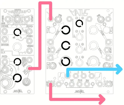
- Useful for creating variations on a modulation or sending CV to inputs that only respond to positive voltages (e.g. Organize CV Input on the PHONOGENE).
SUM OUT
- This is the output from the analog SUM circuit. The inputs are CH. 1, 2, 3, and 4 Variable Outputs. Depending upon how the Attenuverters are set, you could add, invert, or subtract voltages from each other using this circuit.
- This is a good output to use for combining several control signals to generate more complex modulations.
INV OUT
- This is the inverted version of the SUM Output. It allows you to modulate backward!
TIPS AND TRICKS
- Longer cycles are achieved with more Logarithmic response curves. The fastest, sharpest functions are achieved with extreme Exponential response curves.
- Adjustment to the response curve affects the Rise and Fall Times.
- To achieve longer or shorter Rise and Fall Times than available from Panel Controls, apply a voltage offset to the Control Signal Inputs. Use CH. 2 or 3 for this offset voltage.
- Use the INV SUM Output where you require reversed modulation but do not have means for inversion at the CV destination (Mix CV Input on ECHOPHON, for example).
- Feeding an inverted signal from MATHS back into the MATHS at any of the CV inputs is highly useful for creating responses that are not covered by the Vari-Response control alone.
- When utilizing the SUM and OR Outputs, set any unused CH. 2 or 3 to 12:00 or insert a dummy patch cable to the Signal Input of the associated Channel to avoid unwanted offsets.
- If it is desired that a signal processed or generated by CH. 1, 4 is both on the SUM, INV, and OR busses AND available as an independent output, utilize the Unity Signal Output, as it is NOT normalized to the SUM and OR Busses.
- OR Output does not respond to or generate negative voltages.
- End of Rise and End of Cycle are useful for generating complex control voltage functions where CH. 1 and CH. 4 are triggered by one another. To do this, patch EOR or EOC to the other channels’s Trigger, Signal, and Cycle inputs.
PATCH IDEAS
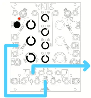
Typical Voltage Controlled Triangle Function (Triangle LFO)
- Set CH.1 (or 4) to Cycle. Set Rise and Fall Panel Control to noon, Vari-Response to Linear.
- Set CH.2 Attenuverter to 12:00.
- Patch SUM Output to Both Control Inputs.
- Optionally, apply any desired frequency modulation to the CH.3 Signal Input and slowly turn its attenuator clockwise.
- Increase the CH.2 Attenuverter to change the Frequency.
- Output is taken from the Signal Output of the associated Channel.
- Setting Rise and Fall parameters further clockwise provides longer cycles. Setting these parameters further counterclockwise provides short cycles, up to audio rate.
- The resulting function may be further processed with attenuation and/or inversion by the associated Attenuverter. Alternatively, take the output from the Cycling Channel’s UNITY Output and patch the Variable Outputs to the Rise or Fall CV Input to morph LFO shapes with the CH.1 (or 4) Attenuverter.
Typical Voltage Controlled Ramp Function (Saw/ Ramp LFO)
Same as above, only the Rise parameter is set fully counterclockwise, Fall parameter is set to at least noon.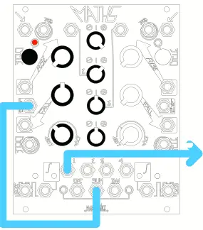
Voltage Controlled Transient Function Generator (Attack/ Decay EG)
- A pulse or gate applied to the Trigger Input of CH.1 or 4 starts the transient function which Rises from 0V to 10V at a rate determined by the Rise parameter and then falls from 10V to 0V at a rate determined by the Fall parameter.
- This function is re-triggerable during the falling portion. Rise and Fall are independently volt-age controllable, with variable response from Log through Linear to Exponential, as set by the Vari-Response panel Control.
- The resulting function may be further processed with attenuation and/or inversion by the Attenuverter.
Voltage Controlled Sustained Function Generator (A/S/R EG)
- A gate applied to the Signal Input of CH.1 or 4 starts the function, which Rises from 0V to the level of the applied Gate, at a rate determined by the Rise parameter, Sustains at that level until the Gate signal ends, and then falls from that level to 0V at a rate determined by the Fall parameter.
- Rise and Fall are independently voltage controllable, with a variable response as set by the Vari-Re-sponse panel Control.
- The resulting function may be further processed with attenuation and/ or inversion by the Attenuverter.
Peak Detector
- Patch signal to be detected to CH. 1 Signal Input.
- Set Rise and Fall to 3:00.
- Take output from Signal Output. Gate Output from EOR Output.
Voltage Mirror
- Apply Control Signal to be mirrored To CH. 2 Signal Input.
- Set CH. 2 Attenuverter to Full CCW.
- With nothing inserted at CH. 3 Signal Input (to generate an offset), set CH. 3 Attenuvert-er to full CW.
- Take output from SUM Output.
Half Wave Rectification
- Apply bi-polar signal to CH. 1, 2, 3, or 4 Inputs.
- Take the output from OR Output.
- Mind the normalizations to the OR bus.
Typical Voltage Controlled Pulse/Clock with Voltage Controlled Run/Stop (Clock, pulse LFO)
- Same as Typical Voltage Controlled Triangle Function, only the output is taken from EOC or EOR.
- CH.1 Rise parameter more effectively adjusts frequency and CH.1 Fall parameter adjusts pulse width.
- With CH.4, the opposite is true, where Rise adjusts more effectively Width and Fall adjust frequency.
- In both Channels, all adjustments to Rise and Fall parameters affect frequency.
- Use CYCLE Input for Run/Stop control.
Voltage Controlled Pulse Delay Processor
- Apply Trigger or Gate to Trigger Input if CH.1.
- Take the output from End Of Rise.
- The rise parameter sets the delay and the Fall parameter adjusts the width of the resulting pulse.
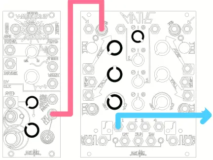
Arcade Trill (Complex LFO)
- Set CH4 Rise and Fall to noon, response to Exponential.
- Patch EOC to a multiple, then to CH1 Trigger Input and CH2 Input.
- Adjust the CH2 panel control to 10:00.
- Patch CH2 Output to CH1 BOTH Input.
- Set CH1 Rise to noon, Fall to full counterclockwise, response to Linear.
- Engage CH4 Cycle switch (CH1 should not be cycling).
- Apply Unity Output CH1 to the modulation destination.
- Adjust CH1 Rise panel control for variation (small changes have a drastic effect on the sound).
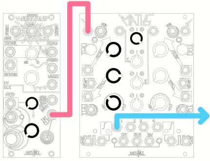
Chaotic Trill (requires MMG or other Direct Coupled LP filter)
- Begin with the Arcade Trill patch.
- Set CH.1 Attenuverter to 1:00. Apply CH.1 Signal Output to MMG DC Signal Input.
- Patch EOR to MMG AC Signal Input, set to LP mode, no feedback. Start with Freq at full counter-clockwise.
- Apply MMG Signal Output to MATHS CH.4 Both Input.
- Patch CH.4 Variable Output to CH.1 BOTH CV Input.
- Unity Signal Output to modulation destination.
- MMG Freq and Signal Input controls and MATHS CH1 and 4 Attenuverters are of great interest in addition to the Rise and Fall parameters.
281 Mode (Complex LFO)
- In this patch, CH1 and CH4 work in tandem to provide functions shifted by ninety degrees.
- With both Cycle Switches engaged, patch the End of RISE (CH1) to Trigger Inverter CH4.
- Patch End of Cycle (CH4) to Trigger Input CH1.
- If both CH1 and CH4 do not begin cycling, engage the CH1 Cycle briefly.
- With both Channels cycling, apply their respective Signal outputs to two different modulation destinations, for example, two Channels of the OPTOMIX.
Typical Voltage Controlled ADSR-type Envelope
- Apply Gate signal to CH1 Signal Input.
- Set CH1 Attenuverter to less than Full CW.
- Patch CH1 End of Rise to CH4 Trigger Input.
- Set CH4 Attenuverter to Full CW.
- Take the output from OR bus Output, being sure that CH2 and CH3 are set to noon if not in use.
- In this patch, CH1 and CH4 Rise control the Attack Time. For typical ADSR, adjust these parameters to be similar (Setting CH1 Rise to be longer than CH4 or vice-versa, produces two attack stages).
- CH4 Fall parameter adjusts the Decay stage of the envelope.
- CH1 Attenuverter sets the Sustain level which must be lower than that same parameter on CH4.
- Finally, CH1 Fall sets the Release Time.
Bouncing Ball, 2013 edition – thanks to Pete Speer
- Set CH1 Rise full CCW, Fall to 3:00, response to Linear.
- Set CH4 Rise full counterclockwise, Fall to 11:00, response to Linear.
- Patch CH1 EOR to CH4 Cycle Input, and CH1 variable Output to CH4 Fall Input.
- Patch CH4 Output to VCA or LPG control Input.
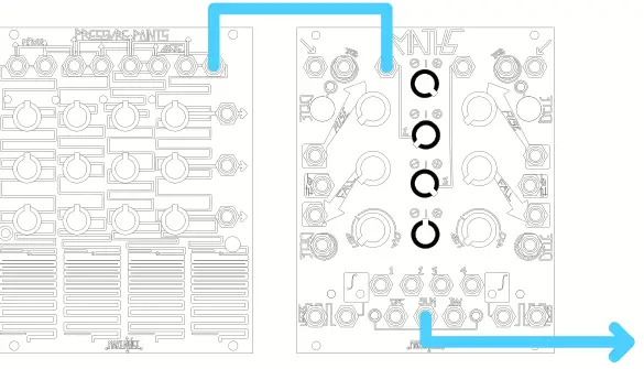
- Patch a Gate or Trigger source (such as the touch gate from Pressure Points) to the CH1 Trigger Input for the manual start of “bounces.”
- Adjust CH4 Rise and Fall for variations.
Independent Contours – thanks to Navs
By changing the level and polarity of the Variable Output of CH1/4 with the Attenuverter, and feeding that signal back into CH1/4 at Rise or Fall Control Input, independent control of the corre-sponding slope is achieved. Take Output from Unity Signal Output. Best to have the Response panel control set to noon.
Independent Complex Contours
- Same as above, but additional control is possible by using the EOC or EOR to trigger the opposite Channel and use the SUM or OR Output to Rise, Fall, or BOTH of the original Channel.
- Alter the Rise, Fall, Attenuversion, and response curve of opposite Channels to achieve various shapes.
Asymmetrical Trilling Envelope – thanks to Walker Farrell
- Engage cycling on CH1, or apply a signal of your choice to its Trigger or Signal Input.
- Set CH1 Rise and Fall to noon with Linear response.
- Patch CH1 EOR to CH4 Cycle Input.
- Set CH4 Rise to 1:00 and Fall to 11:00, with Exponential response.
- Take the output from OR (with CH2 and CH3 set to noon).
- The resulting envelope has a “trill” during the fall portion. Adjust levels and Rise/Fall times.
- Alternatively, swap Channels and use the EOC Output to CH1’s Cycle input for trilling during the rise portion.
Envelope Follower
- Apply signal to be followed to Signal Input CH1 or 4. Set Rise to noon.
- Set and or modulate Fall Time to achieve different responses.
- Take output from associated Channel Signal Output for positive and negative Peak Detection.
- Take the output from OR bus Output to achieve ma ore typical Positive Envelope Follower function.
Voltage Comparator/Gate Extraction w/ variable width
- Apply signal to be compared to CH3 Signal Input. Set the Attenuverter to greater than 50%.
- Use CH2 for comparing voltage (with or without something patched).
- Patch SUM Output to CH1 Signal Input.
- Set CH1 Rise and Fall to full CCW. Take the extracted Gate from EOR.
- CH3 Attenuverter acts as the input level setting, applicable values being between noon and Full CW. CH2 acts as the threshold setting applicable values from Full CCW to 12:00.
- Values closer to 12:00 are LOWER thresholds. Setting the Rise more CW, you can Delay the derived Gate.
- Setting Fall more CW varies the width of the derived Gate. Use CH4 for the nvelope Follower patch, and CH3, 2 & 1 for Gate extraction, and you have a very powerful system for external signal processing.
Full Wave Rectification
- Mult signal to be rectified to both CH2 and 3 Input.
- CH2 Scaling/ Inversion set to Full CW, CH3 Scaling/Inversion set to Full CCW.
- Take the output from OR Output. Vary the Scaling.
Multiplication
- Apply positive going control signal to be multiplied to CH1 or 4 Signal Input. Set Rise to full CW, Fall to Full CCW.
- Apply positive going multiplier Control Signal to the BOTH Control Input.
- Take output from corresponding Signal Output.
Pseudo-VCA with clipping – Thanx to Walker Farrell
- Patch audio signal to CH1 with Rise and Fall at full counterclockwise, or cycle CH1 at audio rate.
- Take the output from SUM out.
- Set the initial level with CH1 panel control.
- Set CH2 panel control full CW to generate a 10V offset. The audio starts to clip and may become silent. If it’s still audible, apply an additional positive offset with CH3 panel control until it is just silent.
- Set CH4 panel control to full CCW and apply envelope to Signal Input or generate envelope with CH4.
- This patch creates a VCA with asymmetrical clipping in the waveform. It works with CV also, but be sure to adjust CV input settings to deal with the large base offset. The INV output may be more useful in some situations.
Voltage Controlled Clock Divider
- The clock signal applied to Trigger Input CH1 or 4 is processed by a divisor as set by the Rise parameter.
- Increasing Rise sets the divisor higher, resulting in larger divisions. Fall time adjusts the width of the resulting clock. If the Width is adjusted to be greater than the total time of the division, the output remains “high.”
FLIP-FLOP (1-Bit Memory)
- In this patch, CH1 Trigger Input acts as the “Set” input, and CH1 BOTH Control Input acts as the “Reset” Input.
- Apply Reset signal to CH1 BOTH Control Input.
- Apply Gate or logic signal to CH1 Trigger Input. Set Rise to Full CCW, Fall to Full CW, Vari-Re-sponse to Linear.
- Take “Q” output from EOC. Patch EOC to CH4 Signal to achieve “NOT Q” at the EOC Output.
- This patch has a memory limit of about 3 minutes, after which it forgets the one thing you told it to remember.
Logic Inverter
- Apply logic gate to CH. 4 Signal Input. Take the output from CH. 4 EOC.
Comparator/Gate Extractor (A New Take)
- Send a signal to be compared to CH2 Input.
- Set CH3 panel control into the negative range.
- Patch SUM out into CH1 Signal Input.
- Set CH1 Rise and Fall to 0.
- Take the output from CH1 EOR. Observe signal polarity with CH1 Unity LED. When the signal goes slightly positive, EOR trips.
- Use the CH3 panel control to set the threshold. Some attenuation of CH2 may be necessary to find the right range for a given signal.
- Use CH1 Fall control to make the gates longer. CH1 Rise control sets the length of time the signal must be above the threshold to trip the comparator.
LIMITED WARRANTY
- Make Noise warrants this product to be free of defects in materials or construction for one year from the date of purchase (proof of purchase/invoice required).
- Malfunctions resulting from wrong power supply voltages, backward or reversed eurorack bus board cable connection, abuse of the product, removing knobs, changing faceplates, or any other causes determined by Make Noise to be the fault of the user are not covered by this warranty, and normal service rates will apply.
- During the warranty period, any defective products will be repaired or replaced, at the option of Make Noise, on a return-to-Make Noise basis with the customer paying the transit cost to Make Noise.
- Make Noise implies and accepts no responsibility for harm to persons or apparatus caused through the operation of this product.
- Please contact technical@makenoisemusic.com with any questions, Return To Manufacturer Authorization, or any needs & comments. http://www.makenoisemusic.com
About This Manual:
- Written by Tony Rolando
- Edited by Walker Farrell
- Illustrated by W.Lee Coleman and Lewis Dahm Layout by Lewis Dahm
- THANK YOU
- Design Assist: Matthew Sherwood
- Beta Analyst: Walker Farrell
- Test Subjects: Joe Moresi, Pete Speer, Richard Devine
FAQ
- Q: Can MATHS be used with digital synthesizers?
- A: MATHS is primarily designed for analog use but can interface with digital synthesizers through Gate/Clock signals.
- Q: How can I create tempo changes using MATHS?
- A: You can create tempo changes by using the Envelope functions and modulating voltages to ramp up or down in tempo.
- Q: What is the purpose of the Cycle Input?
- A: The Cycle Input allows for voltage control of the Cycle state in Channels 1 and 4, enabling cycling based on Gate signals.
Documents / Resources
 |
MAKE NOISE Maths Complex Function Generator Eurorack Module [pdf] Instruction Manual Maths Complex Function Generator Eurorack Module, Maths, Complex Function Generator Eurorack Module, Function Generator Eurorack Module, Generator Eurorack Module, Eurorack Module |