M2M SERVICES NX-8 Cellular Communicators and Programming the Panel
Product Information
Specifications
- Product: Interlogix NX-8
- Model: MN/MQ Series Cellular Communicators
- Document Number: 06046, Ver.2, Feb-2025
Product Usage Instructions
Programming the Panel:
CAUTION: It is recommended that an experienced alarm installer programs the panel for proper performance. Do not route any wiring over the circuit board. Full panel testing and signal confirmation must be done by the installer.
Wiring MN/MQ Series Communicators:
Wiring the MN01, MN02, and MiNi communicator series enables events reporting and remote control via the keybus or keyswitch, depending on the model.
For MN/MQ Series Cellular Communicators
- Remote control via keybus allows you to arm/disarm, arm in stay multiple partitions, bypass zones, and get zone statuses.
- Keybus functionality eliminates the need for keyswitch configuration if supported by the device.
For MQ03 Series Communicators:
- Similar to MN series, enables events reporting and remote control via keybus or keyswitch.
Programming the Interlogix NX-8 Alarm Panel via Keypad:
To enable Contact ID reporting:
- LED LEDs of Ready, Power steady ON Service LED blinks Armed LED steady ON
- Keypad Entry: *8 9713 0# 0#
- Follow the sequence of LED blinks and steady ON indications as per the manual.
CAUTION:
- It is advised that an experienced alarm installer programs the panel as further programming may be required to ensure proper performance and use of the full functionality.
- Do not route any wiring over circuit board.
- Full panel testing, and signal confirmation, must be completed by the installer.
NEW FEATURE: For MN/MQ Series Communicators, the status of the panel can be retrieved not only from the status PGM but now also from the Open/Close reports from the dialer. Therefore, wiring the white wire and programming of the status PGM of the panel is optional.
Wiring the white wire is necessary only if the Open/Close reporting is disabled.
IMPORTANT NOTE: The Open/Close reporting needs to be enabled during the initial pairing procedure.
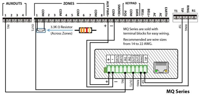
Wiring the MN01, MN02 and MiNi communicator series
for events reporting and remote control via keybus
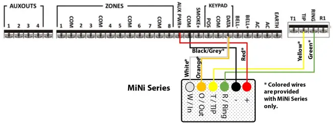
Remote control via the keybus allows you to arm/disarm or arm in stay multiple partitions, bypass zones and get the status of the zones.
Wiring the MQ03 communicator series for events reporting and remote control via keybus
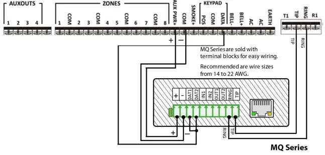
*Remote control via the keybus allows you to arm/disarm or arm in stay multiple partitions, bypass zones and get the status of the zones.
Wiring the MN01, MN02 and MiNi communicator series for events reporting and remote control via Keyswitch*
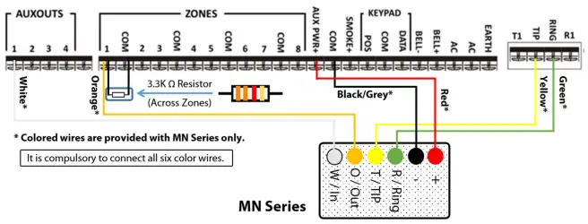 The optional keyswitch configuration can be used for M2M communicators that do not support keybus functionality. You do not need to configure this option if your device supports remote control via the keybus.
Wiring the MQ03 communicator series for events reporting and remote control via Keyswitch
*The optional keyswitch configuration can be used for M2M communicators that do not support keybus functionality. You do not need to configure this option if your device supports remote control via the keybus.
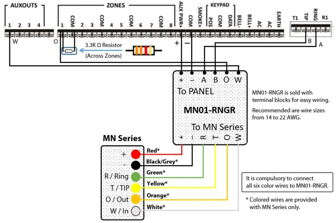
Wiring the MN01, MN02 and MiNi Series with Ringer MN01-RNGR to Interlogix NX-8 for UDL
Programming the Interlogix NX-8 Alarm Panel via the Keypad
Enable Contact ID reporting:
| LED | Keypad Entry | Action Description |
| LEDSs of Ready,
Power Steady ON |
*8 9713 | To enter programming mode |
| Service LED blinks | 0# | To go to main panel programming menu |
| Service LED blinks,
Armed LED steady ON |
0# | To enter phone number menu |
| Service LED blinks, Ready LED steady ON |
15*1*2*3*4*5*6*# |
15* (to choose phone dialing), followed by your desired phone
number (123456 is just an example) each figure is followed by *, # to save and go back |
| Service LED blinks,
Armed LED steady ON |
1# | To go to account number menu |
| Service LED blinks,
Ready LED steady ON |
1*2*3*4*# | Enter the desired account number (1234 is an example), # to
save and go back |
| Service LED blinks,
Armed LED steady ON |
2# | To go to communication format |
| Service LED blinks,
Ready LED steady ON |
13* | To choose Contact ID, * to save |
| All Zone LEDs are ON | 4# | To go to events reported to phone 1 |
| All Zone LEDs are ON | * | To confirm all events reporting and go to next section |
| All Zone LEDs are ON | * | To confirm all events reporting and go back |
| Service LED blinks,
Armed LED steady ON |
23# | To go to feature report section |
| Service LED blinks,
Ready LED steady ON |
** | To go to section 3 of the toggle options menu |
| Ready Led steady ON | 1* | To enable Open/Close reporting |
| Service LED blinks,
Armed LED steady ON |
Exit, Exit | Press “Exit” two times to exit programming mode |
Program Keyswitch zone and output:
| LED | Keypad Entry | Action Description |
| LEDSs of Ready,
Power Steady ON |
*8 9713 | To enter programming mode |
| Service LED blinks | 0# | To go to main panel programming menu |
| Service LED blinks | 25# | To go to zone type menu |
| Service LED blinks,
Ready LED steady ON |
11*# | To set Zone 1 as a Momentary Keyswitch, *# to save and go back |
| Service LED blinks,
Armed LED steady ON |
47# | To go to AUX 1 Output events and time menu |
| Service LED blinks,
Ready LED steady ON |
21* | To choose armed state event as an event that will activate the
AUX 1 |
| Service LED blinks,
Ready LED steady ON |
0* | To disable the output timer (the hold status) |
| Service LED blinks,
Armed LED steady ON |
Exit, Exit | Press “Exit” two times to exit programming mode |
Programming the GE Interlogix NX-8 Alarm Panel via the Keypad for remote Upload/Download (UDL)
Program the Panel for Upload/Download (UDL):
| Display | Keypad Entry | Action Description |
| System ready | *89713 | Enter programming mode. |
| Enter device address | 00# | To go to main edit menu. |
| Enter location | 19# | Start configuring “Download Access Code”. By default, it is “84800000”. |
|
Loc#19 Seg# |
8, 4, 8, 0, 0, 0,
0, 0, # |
Set the Download Access Code to its default value. Press # to save and
go back. IMORTANT! This code should match the one set in the “DL900” software. |
| Enter location | 20# | To go to “Number of rings to answer” menu. |
| Loc#20 Seg# | 1# | Set number of rings to answer to 1. Press # to save and go back. |
| Enter location | 21# | Go to “Download control” toggle menu. |
| Loc#21 Seg# | 1, 2, 3, 8, # | All of these (1,2,3,8) should be OFF in order to disable “AMD” and “Call
back”. |
| Enter location | Exit, Exit | Press “Exit” twice to exit programming mode. |
FAQ
Q: What is the recommended way to program the Interlogix NX-8 panel?
A: It is advised to have an experienced alarm installer program the panel to ensure proper performance and functionality.
Q: When is wiring over the circuit board not recommended?
A: Do not route any wiring over the circuit board to avoid potential issues with the panel’s operation.
Q: What is the purpose of Open/Close reporting in the initial pairing procedure?
A: Open/Close reporting needs to be enabled during the initial pairing procedure to ensure proper communication and functionality.
Documents / Resources
 |
M2M SERVICES NX-8 Cellular Communicators and Programming the Panel [pdf] Owner's Manual MN01, MN02, MiNi, MQ03, NX-8 Cellular Communicators and Programming the Panel, NX-8, Cellular Communicators and Programming the Panel, Programming the Panel |