ASUS EX-B760M-V5 Motherboard Quick Start Guide
This guide provides essential steps for installing and setting up the ASUS EX-B760M-V5 motherboard. It covers CPU installation, fan mounting, memory module insertion, storage device connection, expansion card setup, system panel connector wiring, power connections, and initial system power-on with operating system and driver installation.
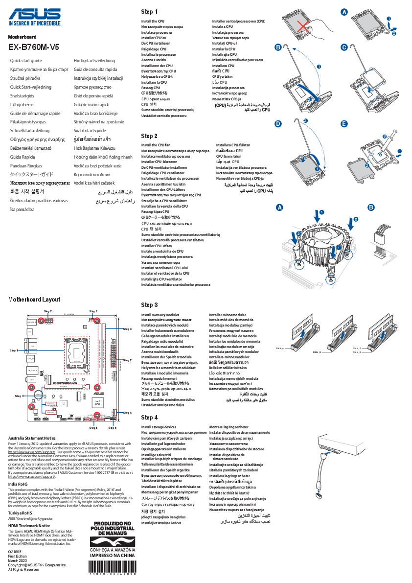
Motherboard Layout
The motherboard features standard component locations. Key areas include:
- CPU Socket (LGA 1700)
- CPU Fan Header
- Memory Slots (DIMM_A, DIMM_B)
- Expansion Slots (PCIEX16, PCIEX1)
- M.2 Slots (M.2_1, M.2_2)
- SATA Ports
- System Panel Connector
- Power Connectors (ATX_PWR, ATX_12V)
- Input/Output Ports (USB, LAN, Audio, HDMI)
Installation Steps
Carefully align the CPU with the socket's triangle indicator and gently lower it into place. Secure the retention arm.
Mount the CPU cooler according to its specific instructions, ensuring it is securely attached to the motherboard. Connect the fan cable to the CPU_FAN header.
Open the clips on the DIMM slots. Align the notch on the memory module with the notch in the slot and press down firmly on both ends until the clips snap into place.
Connect SATA storage devices (SSDs, HDDs) using SATA cables to the SATA ports on the motherboard and to the power supply. For M.2 drives, insert them into the M.2 slots and secure with the provided screw.
Remove the corresponding slot cover from the case. Align the expansion card (e.g., graphics card, network card) with the appropriate PCIe slot and press down firmly until it clicks into place. Secure the card to the case bracket.
Connect the small cables from the computer case (power switch, reset switch, HDD LED, power LED) to the corresponding pins on the system panel connector header on the motherboard. Refer to the motherboard manual for exact pin assignments.
Connect the main 24-pin ATX power connector from the power supply to the ATX_PWR header on the motherboard. Connect the 4-pin or 8-pin ATX 12V power connector from the power supply to the ATX_12V header near the CPU socket.
Connect your keyboard, mouse, monitor (via HDMI or other display outputs), and other peripherals to the appropriate ports on the rear I/O panel.
Connect the power cord, turn on the system using the case power button. Access the BIOS/UEFI setup (usually by pressing DEL or F2 during startup) to verify components. Insert your operating system installation media (USB or DVD) and follow the on-screen prompts to install the OS. After OS installation, install the necessary motherboard drivers (chipset, audio, LAN, etc.) from the ASUS support website or the provided driver CD/USB.
Australia Statement Notice
From January 1, 2012, updated warranties apply to all ASUS products, consistent with the Australian Consumer Law. For the latest product warranty details, please visit https://www.asus.com/support/. ASUS products come with guarantees that cannot be excluded under the Australian Consumer Law. Consumers are entitled to a replacement or refund for a major failure and compensation for any other reasonably foreseeable loss or damage. They are also entitled to have the goods repaired or replaced if the goods fail to be of acceptable quality and the failure does not amount to a major failure. For assistance, please call ASUS Customer Service at 1300 2787 88 or visit https://www.asus.com/support/.
India RoHS
This product complies with the "India E-Waste (Management) Rules, 2016" and prohibits the use of lead, mercury, hexavalent chromium, polybrominated biphenyls (PBBs), and polybrominated diphenyl ethers (PBDEs) in concentrations exceeding 0.1% by weight in homogenous materials and 0.01% by weight in homogenous materials for cadmium, except for the exemptions listed in Schedule II of the Rule.
Türkiye RoHS
AEEE Yönetmeliğine Uygundur
HDMI Trademark Notice
The terms HDMI, HDMI High-Definition Multimedia Interface, HDMI Trade dress, and the HDMI Logo are trademarks or registered trademarks of HDMI Licensing Administrator, Inc.


