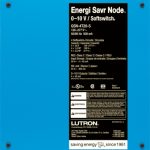
LUTRON Energl Savr Node

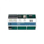
Buttons and LEDs in the unit are used for programming and troubleshooting.
If wiring is exposed when accessing buttons and LEDs, the unit must be accessed by a certified electrician, following local codes.
Note: For additional information on unit operation and ratings, please refer to Lutron P/N 3691206 at www.lutron.com
Mounting
- a. Mount Energi Savr Node (ESN) unit in a position where it can be easily located and accessed if service or troubleshooting is necessary.
- b. Remove outer panel cover.
- c. Remove internal plastic line-voltage shield.
- d. Choose panel mounting location so line voltage wiring is at least 6 ft (1.8 m) from audio and video equipment or radio frequency devices and wiring.
- e. Install in accordance with all national and local electrical codes.
- f. Can be installed in accordance with NEC® Article 300.22(c) “Other places used for environmental air.”
- g. Meets the Canadian National Building Code plenum requirements for a concealed space used as a plenum within a floor or roof assembly.
Control Power Wiring
WARNING! Danger of Shock. May result in serious injury or death. DO NOT WIRE WHEN LIVE! Switch off power to all power feeds via circuit breaker before wiring or servicing the ESN unit. The ESN unit is a feed-through device. This means that each switched output needs the Line and Load wires. THERE IS NO INTERNAL CONNECTION BETWEEN THE CONTROL POWER TO THE UNIT AND THE SWITCHED OUTPUTS.
Note: Control power MUST not exceed 277 V~ even for 347 V~ model
- a. Turn OFF power DO NOT WIRE LIVE, remove metal outer panel cover and internal plastic line-voltage shield.
- b. Wire mains to the unit as shown. Terminals will accept 14 AWG to 12 AWG (2.5 mm2 to 4.0 mm2)
- c. Reinstall plastic line-voltage shield.
- d. Turn ON power and verify that power LED on ESN unit illuminates.
Zone Wiring
WARNING! Danger of Shock. May result in serious injury or death. DO NOT WIRE WHEN LIVE! Switch off power to all power feeds via circuit breaker before wiring or servicing the ESN unit. The ESN unit is a feed-through device. This means that each switched output needs the Line and Load wires. THERE IS NO INTERNAL CONNECTION BETWEEN THE CONTROL POWER TO THE UNIT AND THE SWITCHED OUTPUTS.
- a. Turn OFF power DO NOT WIRE LIVE, remove metal outer panel cover and internal plastic line-voltage shield.
- b. Wire loads to the unit as shown. Terminals will accept 14 AWG to 12 AWG (2.5 mm2 to 4.0 mm2).
- c. Reinstall plastic line-voltage shield.
- d. Turn ON power.
- e. Refer to section 8 for load verification.
QS Link Wiring (IEC PELV / NECR Class 2)

- a. Turn OFF power while servicing the unit, DO NOT WIRE LIVE.
- b. Wire QS link to the module as shown, note terminals 3 and 4 are a twisted screened pair.
- Links may be daisy chained or t-tapped, length not to exceed 2000 ft (610 m).
- Do not connect to terminal 2.
Contact Closure Input
- a. Contact Closure (Emergency and CCI) wiring is IEC PELV / NEC® Class 2. Follow all applicable national and local codes for proper circuit separation and protection.
- b. Turn OFF power while servicing the unit, DO NOT WIRE LIVE.
- c. Remove metal outer panel cover. Terminals will accept 20 AWG to 12 AWG (0.5 mm2 to 4.0 mm2).
- d. Wire “Emergency” and programmable “CCI” to the unit as shown.
- e. The ESN will default to Emergency Mode if the Emergency input is left open. If no Emergency contact is required, please leave the jumper wire in the Emergency input terminals.
0-10 V Wiring (all except QSN2-4S20-S)
- a. Turn OFF power while servicing the unit, DO NOT WIRE LIVE.
- b. Wire 0–10 V zones as shown. Terminals will accept 20 AWG to 12 AWG (0.5 mm2 to 4.0 mm2).
- 0–10 V zones are double-insulated from all other inputs and outputs.
- 0–10 V zones 1-4 are not insulated from each other. They share the same common (negative “–” terminals are internally connected to each other).
- Connect only NEC® Class 2 circuits, or connect only non NEC® Class 2 circuits to 0-10 V zones 1-4.
Do not mix NEC® Class 2 circuits and non NEC® Class 2 circuits. - Follow all national and local codes for separation requirements.
LED Diagnostic Indicators
| LED | LED Behavior | Description |
| CCI (Contact Closure Input) | Continuous on | Contact detected / open |
| Flashing | Contact closed | |
| Off | Contact never detected | |
| Emerg (Emergency Contact Closure Input) | Continuous on | Normal operation / Contact closed/ jumpered |
| Rapid flash | Emergency mode /
Contact open / jumper missing |
|
| QS Link | On / Flashing | Device transmitting / receiving on the QS link |
| 3 quick flashes every 4 seconds | Communication error | |
| Off | Device not transmitting / receiving on the QS link | |
| Zone | Continuous on | Load is on |
| Off | Load is off |
Verify Lights
- a. Use the Raise # and Lower $ buttons for each zone to dim lights up and down.
- b. Confirm all zones behave as expected.
Limited Warranty
Warranty [PDF]
![]()
Documents / Resources
 |
LUTRON Energl Savr Node [pdf] Instructions QSN2-4T20-S, QSN2-4T16-S-347, QSN2-4S20-S, Energl Savr Node |