
LINK-MI LM-TV12P Video Wall Controller User Manual

Model No.: LM-TV12P
Dear Customer
Thank you for purchasing this product. For optimum performance and safety, please read these instructions carefully before connecting, operating or adjusting this product. Please keep this manual for future reference.
- Make sure that all devices you will be connecting up are properly grounded.
- Make sure that the power to all the devices you will be connecting up has been turned off.
- Do not place other objects on the cable.
- Risk of electrical shock, do not open.
- To avoid damaging the product, do not dismantle it by yourself, the device should be repaired and maintained by the professional and qualified personnel in the designated service center.
- Do not place any object into the opening of the casing, otherwise, it might cause voltage or short circuit incident.
- The installation site must be well ventilated. Ensure that air vents on the equipment are not blocked.
1st Introduction
This 3×4 video wall controller support 1x HDMI 2.0 in, 1x HDMI 1.4 in and 1x DP 1.2 in, max resolution support 4K@60Hz 4:4:4 HDCP 2.2. It allows any of 3 inputs routed to the 12 HDMI outputs. Users can choose different video mode via remote like 3×4 video wall mode, PIP (picture in picture) mode etc to meet their needs .
This 4K video wall controller offers solution for home, office, digital entertainment, center, conference room, school and other digital TV use environments.
2nd Feature
- 3×4 video wall controller comes with 1x HDMI 2.0 in, 1x HDMI 1.4 in and 1x DP in; 12x HDMI out.
- Max resolution up to 4K@60Hz 4:4:4, HDCP 2.2, DP 1.2 max 4K@60Hz.
- Easy to set-up and control,support control via front buttons and remote.
- Support image rotation 90°, 180°, 270° and Mirror left and right, flip up and down.
- Support 3.5mm analog audio out.
- Support automatically adjust border function and crop image function, Display without black edges.
- Support roaming window and support input of the splicer can be resize and positioned at any position .
- Supports intelligent temperature control protection technology, making the product’s heat dissipation performance more stable, reliable and durable.
- Silent smart fan, no noise at work.
3rd Package Content
- 1x Main Unit (4K 3×4 Video Wall Controller)
- 1x Power Cable
- 1x Remote
- 1x User Manual
4th Technical Parameters


5th Panel Description
1. Front Panel

2. Rear Panel

3. Remote Description

6th Connection

7th Installation
Take LM-TV09P (9 HDMI outputs) as sample.
- Connect the input source(HDMI1 /HDMI2 /DP) to the video wall controller.
- output ports connect 9 TVs.
- Use remote or press front button MENU to select splicing menu,(User can use LEFT, RIGHT, UP and DOWN choose splicing mode), set mode to 3×3.

4. Select HDMI port NO. And splicing NO. And adjust according to the prompts in the upper left corner of the screen (for example: 3×3 mode, set the first screen HDMI port to 1 and the Splice Position number is 1 ,and the upper left corner will show : Splice Mode 3×3, HDMI port 1 and Splicelnder 1)

5. The other 8 screens setting are the same.
6. Press SOURNU+ LETF/RIGHT key to choose and switch input signal. If via remote can Press INPUT+ LEFT/RIGHT key)

8th Roaming Window settings
1. Press MENU+LET/RIGHT key into roaming window mode. Then press HIGH/LOW key select Roaming windows mode and press OK to choose ,the roaming windows mode support 1 P, 2PLR , 2PTR, PIP, 4P mode .

2. Press OK button to enter PIP mode.

3. Press SOURNU +left /right keys to select the input signal or (remote INPUT+ left/ right key) to switch the first screen signal to HDMI 1 Press OK to select the first window, so that the icon runs to the switching signal and press left and right to adjust to the switch Confirm the signal with OK.

(USER can adjust the PIP position, transparency and size by remote. also can save display mode to 1-9.then next time you can press 1-9 key use saved mode directly. )
9th Video mode


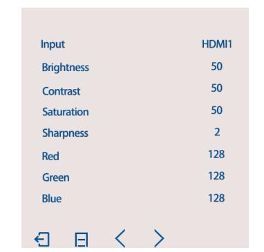
1. Image menu: adjust brightness, chroma, contrast.
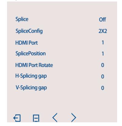
2. Setup menu: Set splicing mode, splicing position, border blanking; border blanking function: this function only takes effect when the screen is in splicing state, the default value is zero, and adjusting the size of this value can remove part of the border image
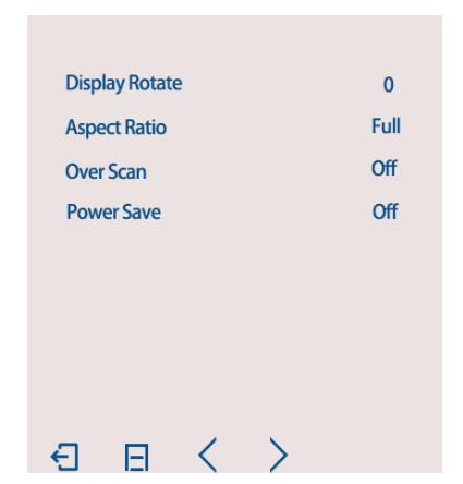
3. Image menu: Image rotation, adjust screen scale mode, automatic dormancy; image rotation: can rotate 90 degrees , 180 degrees , 270 degrees, left and right mirror, up and down mirror flip. Proportional pattern: support 16:9 4:3 5:4 1: 1.
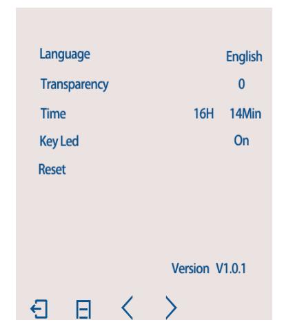
4. Time menu: Set language, restore factory settings, panel key light turn on/off.
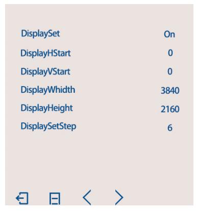
5. Cutting Black Edge: Adjusts the horizontal vertical position only in the 1 P(3×3 video wall mode) splicing state, sets the image width height .
11th Trouble shooting
No Image
- Verify the input source is powered on and connected with controller box.
- To confirm display device is turned on and connected with controller box .
- Check the system connection status.
- Check the cable is intact.
- Try restarting the device to re-catch the signal.
- Try to use another input source.
- Check if select a correct signal.
No response use remote
- Check if there is any abnormality in the remote control and whether there is a battery.
- Check if the distance is too far and if there are any obstacles in the middle.
Image out of order
- Check whether the row and column positions are set correctly.
- Check whether the screen serial number is consistent with the controller box HDMI outputs.
Image blurred
- Re – plug the connector to prevent the socket interface is bad.
- Wire quality (HDMI cable requirements in line with HDMI 1.4 standard)
- Check the screen and the input source.
SHENZHEN LINK-MI TECHNOLOGY CO., LTD.
WWW.LINK-MI.COM E-mail: sales@link-mi.com
Read More About This Manual & Download PDF:
Documents / Resources
 |
LINK-MI LM-TV12P Video Wall Controller [pdf] User Manual LM-TV12P Video Wall Controller, LM-TV12P, Video Wall Controller, Wall Controller, Controller |