Libiao ROBOTICS AirRob Control Bin

Specifications
- Model: LBAirBox
- Version: V1.0
- Date: June 2024
- Manufacturer: Zhejiang Libiao Robotics Co., Ltd
- Address: No.96, Changda Road, Linping Street, Linping District, Hangzhou City, Zhejiang Province, China
Overview
The company has increased investment and conducted in-depth research in warehouse automation and retrieval technology, developing the “Li Biao” warehouse automation and retrieval technology. The control bin is mainly composed of a supercapacitor board, a power control board, a main control board, an inclinometer, and a communication antenna. The control bin is one of the important components of the AirRob system and is a key device for achieving automated storage and retrieval of warehouse bins.
Model Definition
- Control Box Model: BAirBox,
This operating manual applies to the control box model of this rail machine.
Features
- Simple structure design, low cost, easy to install, and deploy.
- Optimize power usage. efficiency The power control within the control box ensures the supply and stability of power, guaranteeing that all components of the rail machine receive a stable power supply.
- Automatic tilt correction
The rail machine is equipped with an internal tilt sensor that can detect the tilt angle of the machine body in real time. Based on the tilt angle, the rail machine automatically corrects itself to maintain vertical alignment at all times.
Technical Parameters
The basic technical parameters are as follows:
| Category | Project | Parameter | Illustrate |
| Mechanical parameters | Altitude | 2500 mm~9000 mm | Highly customizable |
| Width | 764 mm | ||
| Depth | 820 mm | ||
| Weight | 50~65kg | Based on height variations | |
| Electrical parameters | Operating voltage | DC25V~DC29V | |
| Operating current | 5.6A,12A | 12A for charging current | |
| Operating power | 150W,350W | 350W for charging power | |
| Power supply mode | Pure copper wire static contact | Pure silver contact touch | |
| Communication
interfaces |
900M wireless, WIFI
(2.4G/5G) |
||
| Driving mode | DC servo motor | ||
| Movement speed | Horizontal (X) | Velocity ≤ 2.0M/S,
Acceleration≤2.0M/S² |
|
| Vertical (Z) | Velocity ≤ 1.0M/S,
Acceleration≤0.8M/S² |
||
| Bin pulling time | 4.5 seconds/time | ||
| Pushing the bin takes time | 4.5 seconds/time | ||
| Features |
Bin specifications |
Length× width:530mm ×410mm |
There must be handholds on
the front and rear sides |
| Payload | ≤30kg | ||
| Barcode supported | 1D and 2D codes | ||
| Environmental conditions | Operating temperature | -20℃-55℃ | |
| Operating humidity | ≤95%RH | ||
| Storage temperature | -45℃-65℃ | ||
| Storage humidity | ≤90%RH | ||
| Altitude | ≤3000 meters |
Basic Technical Parameters of the Control Box
Composition and Working Principle of the Control Box
Main Body of the Control Bin
The main control bin is primarily composed of a super capacitor board, power control board, main control board, inclinometer, and communication antenna, as shown in the di. The diagram below Main Control Bin Body.
Super Capacitor Board
The super capacitor board consists of three units grouped, operating within a voltage range of 21V to 29V. These super capacitor boards are monitored by the power control board to ensure they function within a safe voltage range. The primary role of the super capacitor board is akin to an energy storage reservoir. When the motor is ascending and needs to overcome gravity, the power demand is high. At this time, the super capacitor board can provide additional power support to prevent the motor from stopping or falling due to an insufficient power supply. The super capacitor board remains fully charged during normal operation, ready to quickly release energy when the motor requires it. During motor descent, the power demand is lower due to the assistance of gravity. The super capacitor board can recover and store the excess energy generated during motor descent through an energy recovery mechanism. This method not only improves energy utilization efficiency but also reduces dependence on external power sources. Each super capacitor board is equipped with a battery management chip that monitors the charging and discharging status in real-time. The battery management chip can detect whether the charging and discharging processes are normal, and if any abnormalities are detected, it can promptly shut down the charging and discharging circuits to ensure system safety. This monitoring and management mechanism ensures the reliability and longevity of the super capacitor board. The super capacitor board works in conjunction with the power control board to ensure a stable power supply. The power control board continuously monitors the status of the super capacitor board and dynamically adjusts power distribution to optimize system performance. The electrical control bin provides the basic power supply for the motor, and when the control bin cannot meet the motor’s demand, the super capacitor board offers additional support. This interaction ensures that the motor receives adequate power support under various operating conditions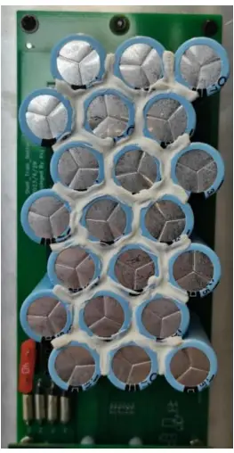
Power Control Board.
The power control board is responsible for charging and supplying power to peripheral devices. It is the core power controller of the rail machine system, managing the entire system’s power supply. It ensures that all components of the rail machine receive a stable power supply. The power control board continuously monitors the power status, including parameters such as voltage and current. Through monitoring, it can promptly detect power abnormalities, preventing power issues from affecting the normal operation of the rail machine. The power control board is responsible for power distribution and management, ensuring that the power needs of various components are reasonably met. It can dynamically adjust power distribution according to the needs of different components, optimizing power usage efficiency. The power control board directly controls the power supply to the motor, ensuring the motor receives stable power support. It monitors the power status of the motor to prevent motor failures due to power issues. Among the components, the CAN interface on the power control board is very common in the rail machine system and plays an important integrative role. It simplifies the system’s power and communication wiring, enhancing system reliability and maintainability. The two power lines in the CAN interface are responsible for providing power control functions, ensuring power supply and stability. The two communication lines in the CAN interface are responsible for data transmission, facilitating information exchange between various components within the system. Through CAN communication, the power control board can interact with other system components in real-time, ensuring coordinated operation of the system.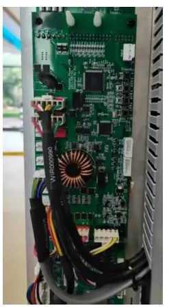
Main Control Board
The main control board governs the entire operation of the rail machine. All logical control and external communications of the rail machine are achieved through internal connections, with no external connection wires. The modules on the main control board are divided into a WiFi module and a 900 MHz communication module. The WiFi module’s function is to provide a virtual WiFi network. Its characteristic is strong data transmission capability but weak anti-interference ability. The 900 MHz communication module’s function is to provide communication in the 900 MHz frequency band. Its characteristic is strong anti-interference ability, but it cannot handle large data transmissions. The two modules operate in different frequency bands (WiFi and 900 MHz), complementing each other. The main control board plays a role in action control and data collection. It can receive commands and collect data, receiving commands from the vehicle service system and gathering data from other sensors, including radar, control motors, batteries, etc., ensuring the normal operation of the system’s Main Control Board.
Tilt Sensor
The tilt sensor is primarily used to adjust the posture of the rail machine, ensuring that it remains upright while operating on the rail. It also helps detect speed discrepancies between the upper and lower wheels, preventing the rail machine from tilting due to inconsistent speeds. By continuously monitoring and adjusting in real-time, the tilt sensor ensures all wheels operate synchronously, maintaining the balance of the rail machine. The tilt sensor continuously monitors changes in the rail machine’s posture and provides feedback data to the control system. Based on the data from the tilt sensor, the control system makes necessary adjustments to ensure the rail machine remains stable throughout its operation, without any tilting or deviation. 
Principles of Electrical (Wiring)
Electrical (wiring) Schematic Electrical (Wiring) Schematic Diagram
Device and Address
| Serial
number |
Name | Illustrate |
| 1 | Main Board | Server communication address |
| 2 | Power Board | CAN communication address |
| 3 | Tilt Sensor |
Table 4. Control Box Equipment and Communication Addresses
The operating voltage of the control box is DC 27V (nominal voltage, actual range DC 25V – DC 29V). The communication interfaces use 900M wireless communication and WiFi (2.4G/5G). Communication between the main control board and the equipment is via CAN bus.
CAN-Plus Interface
The CAN-Plus interface is based on the standard CAN bus and adds 2P power supply, that is, VH-4+VH-2.
- DC27V+
- CAN-H
- DC27V-
- CAN-L
- DC27V+
- DC27V

CAN-Plus interface definition
Installation and Debugging
Installation
As shown in the figure below, use M36+6 hex standoffs, M311+6 hex standoffs, and M3*5 pan head screws to securely mount the finished circuit board onto the circuit board bracket.
 Circuit Board Installation Diagram. Pay attention to the usage positions of the two types of hex standoffs; ensure that the WIR000617 cable is pre-inserted into the tilt sensor board. For the connection positions of each terminal on the circuit board, see the diagram below.
  Circuit Board Connection Diagram
Debugging
Check Before Powering On
Before powering on the control box, a comprehensive inspection must be carried out. This includes checking whether all components are installed, whether any screws are missing or not tightened properly; also, check if the wiring is correct, if the cables are properly secured with zip ties, and finally, use a multimeter to measure if there is a short circuit between the DC 27V connections.
Powering on the equipment
Observe whether all devices and sensors in the control box are powered on and functioning normally (this can be verified through the status of the LED indicators). All devices other than the main control board should have their LED indicators flashing rapidly if they are working normally. If the LEDs are flashing slowly, check whether the CAN-H and CAN-L connections of the CAN bus are correct.
Changing the address of the main control board
After all the equipment is powered on, the equipment address (IP) of the AirBox needs to be changed according to the actual on-site network configuration. To change the address, you need a PC and a USB to CAN tool, as well as the configuration software (RackRailTool.exe) of the AirBox. Connect the USB to CAN tool to the computer, then plug it into any CAN bus interfaces (VH-4) on the rail machine and open the configuration software:  Basic Parameter Change Interface.
- Select USB2CAN to start the connection, after normal connection, both the CAN bus status and the AirRob status are displayed online.
- Select the parameters you want to change, and click Save when the changes are complete.
Basic parameter list:
| Parameter | Default value | Illustrate |
| Address the car number | 104101 | The IP address of the device is 192.168.104.101 |
| Broadcast address | 238238 | LB-AP Broadcast address for wireless communication |
| HOME channel | 0 | LB-AP Channel for wireless communication startup |
| Fundamental frequency | 902 | LB-AP The starting frequency of the wireless
communication |
| Frequency
interval |
250 | LB-AP Frequency interval when communicating
wirelessly |
| Power range | 120 | LB-AP The transmit power of wireless communication |
| World coordinates-X | 0 | The default X coordinate of the orbiter in the AirRob
system |
| World
coordinates – Y |
0 | The default Y coordinate of the orbiter in the AirRob
system |
| Z-axis height above the ground | 150 | The height of the synchronous belt conveyor surface from the ground when the push-pull bin machine is placed at the lowest location, measured in millimeters. |
| Push-pull camera height difference | 0 | The height difference in the front-to-back direction of the push-pull box machine, measured in millimeters. |
Table 2. Basic Parameters List
Because the push-pull bin machine is fixed on the column on one side, the height of the outer side is often a little lower than that of the column side, resulting in a little deviation from the height of the reverse rack operation, and the parameter of this height difference is needed to correct and compensate. Schematic diagram of the front-to-back height difference of the push-pull bin machine
Note: After the above parameters are saved, you need to restart the main board to take effect, and the restart method is referred to the corresponding section below.
Profile Download
In addition to the basic parameters, you also need to download the corresponding PCFG configuration file (rackrail.pcfg). The main network parameters, motor parameters, running speed, lidar, and other related general parameters of the AirRobare are specified in this configuration file.
Note: The main control board needs to be restarted after the parameters have been downloaded for them to take effect. Refer to the following section for the restart method.
Inclination Zero Calibration
When powering on for the first time, the rail machine requires azero inclination calibrationn. There are two specific methods for correction: using the main control board buttons or the rail machine interface on the server software.
Main board buttons
The main board is equipped with 3 buttons and communication transceiver indicators, as shown in the following figure
 Rail Machine Main Control Board
- The function keys 1 and 2 of the main board have different functions in different states.
- The motherboard reset button is used to reset and restart the main board.
- The communication LED indicator of the main board, and the communication transmission and reception corresponds to an LED indicator.
- The method and specific steps of tilt zero calibration through the main board are as follows:
- Press and hold the keys ①and②at the same time and do not let go, and then press the keys③again to reset and restart the board;
- After seeing④the two LED indicators flash synchronously for 0.5 seconds, let go of①and②, and then you can correct the tilt zero location;
- Push the AirRob to the vicinity of the rack column, and the reference column straightens the AirRob until it is 90 degrees vertical.
- Then press①and②at the same time until④the two LED indicators turn off, and the calibration of the saved data is completed.
Software Upgrade
The electrical control equipment in the control box includes the supercapacitor board, power control board, main control board, inclination sensor, and other devices. The specific upgradable contents are listed in the table below:
| Equipment | Upgrade content | Illustrate |
| Main board | RackRail_xxx.up、RackRail_xxx.pcfg | The upper file is the encrypted program file of the device, and the
PCFG file is the configuration file of the main board. |
| Power Board | TrackPower_xxx.up | |
| Tilt sensor | LBRackRailGyroAcc_xxx.up |
Device upgrade files
The upgrade files listed in the above table can be upgraded either locally or remotely.
Local Method
Tools required for local upgrade method: computer, adjustable power supply, USB to CAN tool and connecting cables, tool software, etc. Upgrade tool
The local upgrade is mainly to use the USB to CAN tool to download files or other data to the storage flash of the device through the CAN bus interface of the device and the corresponding tool software. Tools include
- Device Registration Software (dev_register.exe)

- Configure the download tool (LBRobotConfigTool.
The device registration software is used to upgrade the “UP” program file, and the configuration download tool is used to download the PCFG configuration file.
Main board
The upgrade of the main board includes two types: the “UP” program file and the pcfg configuration file.
up program file
To upgrade the file of the UP program, you need to use the device registration software (dev_register.exe), connect the device, open the tool, select the corresponding UP file, and click on the update program. Up program file download
The tool will find a device and start downloading the UP data to the device, when the progress is 100.0% complete, the upgrade is complete.
pcfg configuration file
The main board also has a PCFG configuration file (general configuration parameters of the AirRob) that also needs to be updated, and can also be downloaded to the control board through the tool software. Pcfg configuration file download
Select the device type as rail Machine (0x30). During the configuration file download process, there is a certain probability that “Download Failed” may be displayed. In this case, click “Write” again until the download shows “100.0% Success” to ensure the download is successful.
Power Board
The local upgrade method for the power board is the same as the UP program method for the main control board.
Inclinometer
The local upgrade method for the inclinometer is the same as the UP program method for the main control board. The voltage is DC 5V, and it uses a GH-4 interface.
FAQs
Q: Can the AirRob Control Bin be used outdoors?
A: The AirRob Control Bin is recommended for indoor use to minimize interference with co-channel mobile satellite systems.
Q: What should be done if there is interference during operation?
A: The device must accept any interference encountered, including that which may cause undesired operation. Ensure compliance with regulations for continued operation.
Documents / Resources
 |
Libiao ROBOTICS AirRob Control Bin [pdf] User Manual 2AQQMLBAIRBOX, lbairbox, AirRob Control Bin, AirRob, Control Bin, Bin |