![]() Micro PV Inverter
Micro PV Inverter
User Manual
LSMT1200TL
LSMT1400TL
LSMT1600TL
LSMT2000TL
LSMT Series Micro PV Inverter
Document Revision: V1.0
About Microinverter
This system is composed of a group of Microinverters that convert direct current (DC) into alternating current (AC) and feeds it into the public grid. The system is designed for the incorporation of one Microinverter for four photovoltaic modules. Each Microinverter works independently that guarantees the maximum power generation of each photovoltaic module. This setup enables user to control the production of a single photovoltaic module directly, consequently improving the flexibility and reliability of the system.
About the Manual
This manual contains important instructions for the LSMT1200TL/LSMT1400TL/LSMT1600TL/LSMT2000TL Microinverter and must be read in its entirety before installing or commissioning the equipment. For safety, only qualified technician, who has received training or has demonstrated skills can install and maintain this Microinverter under the guide of this document.
Important Safety Instructions
This manual contains important instructions to follow during installation and of the Photovoltaic Grid-connected Inverter (Microinverter). To reduce the risk of electrical shock and ensure the safe installation and operation of the Microinverter, the following symbols appear throughout this document to indicate dangerous conditions and important safety instructions.
Specifications subject to change without notice – please ensure you are using the latest manual found at the manufacturer website.
WARNING: This indicates a situation where failure to follow instructions may cause a serious hardware failure or personnel danger if not applied appropriately. Use extreme caution when performing this task.
*Note: This indicates information that is important for optimized microinverter operation. Follow these instructions strictly.
1.1 Safety Instructions
![]() DO NOT disconnect the PV module from the Microinverter without disconnecting the AC power.
DO NOT disconnect the PV module from the Microinverter without disconnecting the AC power.
![]() Only qualified professionals should install and/or replace the Microinverters.
Only qualified professionals should install and/or replace the Microinverters.
![]() Perform all electrical installations in accordance with local electrical codes.
Perform all electrical installations in accordance with local electrical codes.
![]() Before installing or using the Microinverter, please read all instructions and cautionary markings in the technical documents and on the Microinverter system and the Microinverter solar-array.
Before installing or using the Microinverter, please read all instructions and cautionary markings in the technical documents and on the Microinverter system and the Microinverter solar-array.
![]() Be aware that the body of the Microinverter is the heat sink and can reach a temperature of 80℃ . To reduce risk of burns, do not touch the body of the Microinverter.
Be aware that the body of the Microinverter is the heat sink and can reach a temperature of 80℃ . To reduce risk of burns, do not touch the body of the Microinverter.
![]() DO NOT attempt to repair the Microinverter. If it fails, contact technical support to obtain an RMA number and start the replacement process. Damaging or opening the Microinverter will void the warranty.
DO NOT attempt to repair the Microinverter. If it fails, contact technical support to obtain an RMA number and start the replacement process. Damaging or opening the Microinverter will void the warranty.
![]() Caution!
Caution!
The external protective earthing conductor is connected to the inverter protective earthing terminal through AC connector.
When connecting, connect the AC connector first to ensure the inverter earthing then do the DC connections.
When disconnecting, disconnect the AC by opening the branch circuit breaker first but maintain the protective earthing conductor in the branch circuit breaker connect to the inverter, then disconnect the DC inputs.
![]() In any circumstance, do not connect DC input when AC connector is unplugged.
In any circumstance, do not connect DC input when AC connector is unplugged.
![]() Please install isolation switching devices on the AC side of the inverter.
Please install isolation switching devices on the AC side of the inverter.
1.2 Radio Interference Statement
CE EMC Compliance:The equipment can comply with CE EMC, which are designed to protect against harmful interference in a residential installation. The equipment could radiate radio frequency energy and this might cause harmful interference to radio communications if not following the instructions when installing and using the equipment. But there is no guarantee that interference will not occur in a particular installation. If this equipment causes harmful interference to radio or television reception, the following measures might resolve the issues:
A) Relocate the receiving antenna and keep it well away from the equipment.
B) Consult the dealer or an experienced radio / TV technical for help. Changes or modifications not expressly approved by the party responsible for compliance may void the user’s authority to operate the equipment.
1.3 The Meaning of Symbols
| Symbol | Usage |
| Treatment To comply with European Directive 2002/96/EC on waste Electrical and Electronic Equipment and its implementation as national law, electrical equipment that has reached the end of its life must be collected separately and returned to an approved recycling facility. Any device no longer required must be returned to an authorized dealer or approved collection and recycling facility. |
|
| Caution Do not come within 8 inches (20cm) of the microinverter for any length of time while it is in operation. |
|
| Danger of high voltages Danger to life due to high voltage in the microinverter. |
|
| Beware of hot surface The inverter can become hot during operation. Avoid contact with metal surfaces during operation. |
|
| CE mark The inverter complies with the requirements of the Low Voltage Directive for the European Union. |
|
 |
Read manual first Please read the installation manual first before installation, operation and maintenance. |
Microinverter System Introduction
2.1 About 4 in 1 Unit
“4-in-1 Unit Microinverter” with ultra-wide DC input operating voltage range (22 V–60 V) and low start-up voltage (22 V only).
2.2 Microinverter Highlights
- Maximum output power of 1200W / 1400W/1600W/2000W. Adapt to 60 & 72 & 144 cell photovoltaic panels.
- The peak efficiency was 94.70%. The CEC-weighted efficiency was 94.50%.
- Static MPPT efficiency is 99.80%. Dynamic MPPT efficiency was 99.76% on overcast days.
- Power factor (adjustable) 0.8 ahead… 0.8 lag.
- High Reliability: NEMA 3R (IP67) housing.6,000 V Surge Protection.
2.3 Terminals Introduction

| Object | Description |
| A | AC Connector (Female) |
| B | DC Connectors |
About Function
3.1 Work Mode
Normal: Under this mode, Microinverter is operating normally and convert DC power into AC power to support the house loads and feed in to Public Grid.
Stand by: When The current condition is contradicted with Microinverter operating requirement, Microinverter will stay in Standby mode.
About Installation
4.1 Accessories

| Object | Description |
| A | AC handshake cable (double male), 3 * 4mm cable 1m |
| B | 8× 20mm screw |
| C | AC female end cover |
| D | *AC grid connection cable (MALE + AC7-7) |
*Note: the AC grid connection cable is an optional accessory that is not included in the package and needs to be purchased separately. Please contact our sales representative for pricing information.
4.2 Installation Precaution
Please install the Microinverter and all DC connections under the PV module to avoiding direct sunlight, rain exposure, snow layup, UV etc. Allow a minimum of 5cm of space around the microinverter enclosure to ensure ventilation and heat dissipation.
4.3 Space Distance Required
If the microinverters are installed on a concrete roof or steel roof, the communication with the WIFI may be slightly affected. Under such installation conditions, it is better for the microinverters to be installed 50cm above the roof. Otherwise, WIFI amplifier may be required to ensure the communication quality between the WIFI and the microinverters.

4.4 Preparation
Installation of the equipment is carried out based on the system design and the place in which the equipment is installed.
- The installation must be carried out with the equipment disconnected from the grid (power disconnect switch open) and with the photovoltaic modules shaded or isolated.
- Referring to the Technical Data to make sure the environmental conditions fit the microinverter’s requirement (degree of protection, temperature, humidity, altitude, etc.)
- To avoid power de-rating due to an increase in the microinverter internal temperature, do not expose it to direct sunlight.
- To avoid overheating, always make sure the air flow around the inverter is not blocked.
- Do not install in places where gasses or flammable substances may be present.
- Avoid electromagnetic interference that can compromise the correct operation of electronic equipment. When choosing the position of installation, comply with the following conditions:
- Install only on structures specifically conceived for photovoltaic modules (supplied by installation technicians).
- Install Microinverter underneath of the photovoltaic modules to make sure it works in the shadow. If this condition cannot be met, might trigger the inverter production de-rating.
4.5 Installation Steps
4.5.1
Step 1. Attach Microinverter on Rail.
A) Mark the approximate center of each panel on the frame.
B) Fix the screw on the rail.
C) Hang the microinverter on the screw , and tighten the screw. The black cover side of the microinverter should be facing the panel.

4.5.2
Step 2. Connect AC Cables of Microinverter
A). Plug the AC connector of the first microinverter into the connector of the second microinverter to form a continuous AC branch circuit.
B). Install the AC end cap on the open AC connector.

*Note: The length of AC cable on microinverter is roughly 1m, if the distance between two microinverters is more than 1m, please use an AC extension cable between two microinverters.
C). The AC handshake cable diagram shows
a). AC handshake cable components
 b). Schematic diagram of male terminal hole position

c). AC grid connection cable diagram

*Note: Using the AC grid-connected cable, it can be plugged directly into the socket Fast grid connection for use, the maximum number of machines with 3 sets;
In the same branch: @120V maximum number is 3; @230V maximum number is 6(Custom cables are required)
4.5.3 Step 3. Create an Installation Map
Affix the serial number label to the respective location on the installation map.
| Microinverter Installation Map V1.1 | ||||||||||||||||
Please Make N for North  |
Panel Type: Azimuth: Tilt: Sheet of : |
Customer Information: | ||||||||||||||
| 1 | 2 | 3 | 4 | 5 | 6 | 7 | 8 | 9 | 10 | 1 | 12 | 13 | 14 | 15 | 16 | |
| A | ||||||||||||||||
| B | ||||||||||||||||
| C | ||||||||||||||||
| D | ||||||||||||||||
| E | ||||||||||||||||
| F | ||||||||||||||||
4.5.4 Step 4. Connect PV Modules
A) Mount the PV modules above the microinverter.
B) Connect the PV modules’ DC cables to the DC input side of the microinverter.

4.5.5 Step 5. Energize the System
A) Turn on the AC breaker of the branch circuit.
B) Turn on the main AC breaker of the house. Your system will start to generate power after about two minutes of waiting time.
4.5.6 Step 6. Set Up the Monitoring System
Refer to the chapter 5 Section Monitoring System ( Monitoring Platform) Online Registration to install the APP and set up your monitoring system.
Monitoring System
5.1 Bluetooth mode
Note: the mobile phone and the inverter should be on the same 2.4G WiFi,make sure the WIFI signal is good when you are near the device and the Bluetooth should be turned on. Two mobile phones cannot be connected at the same time. When changing the mobile phone connection, you need to unbind the last bound mobile phone.
The CLOUD INTELLIGENCE APP Download address is as below(Scan QR code as below):
 https://g.aliplus.com/ilop/d.html?locale=all&pk=a1VasCbj3qX
A) Open the APP and open the Bluetooth function of the mobile phone, and then click the “+” icon in the upper right corner of the app home page to add a device.

B) On the automatic adding inverter page, when the inverter appears in the list, click the “+” sign.

Select the Wi Fi signal currently connected to the mobile phone and input the Wi Fi password; Click next.

C) The system will enter the network configuration state and wait for the completion of the distribution network.
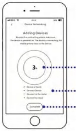
Troubleshooting
5.2 Wifi mode
A) If you fail to use Bluetooth for network distribution, you can use this method for network distribution and click Scan QR code for operation.

B) Scan the QR code as below. (scan within 3 meters as close to the equipment as possible, and ensure good WIFI signal).
 https://g.aliplus.com/ilop/d.html?locale=all&pk=a1VasCbj3qX
C) Select the Wi Fi signal currently connected to the mobile phone and input the Wi Fi password; Click next.

D) The system will enter the network configuration state and wait for the completion of the distribution network.

6.1 Status LED Indicator
- The LED flashes (3s interval) at start up without WIF. When the DC voltage and AC voltage is normal, enter the start state.
- When the inverter is started and has been connected to Internet, the LED indicator status is as follows
① When the inverter is not working: the red light is always on;
② Inverter operation: blue light flashing ( Long blue light when MPPT locked). - When the inverter is started but not connected to the Internet, the LED indicator status is as follows
① When the inverter is not working: the red light flashes
② When the inverter is operating state: blue light flashing (Long blue light when MPPT locked), alternately red light flashing (3s interval). - Other states:When DC voltage and AC voltage are normal, red light on/off: inverter is damaged*.
* Note: Please refer to the Cloud intelligent monitoring platform for more information.
6.2 On-site Inspection (For qualified installer only)
To troubleshoot an inoperable microinverter, follow the steps in the order shown.
- Verify the utility voltage and frequency are within ranges shown in the in appendix Technical Data of this microinverter.
- Check the connection to the utility grid. Verify utility power is present at the inverter in question by removing AC, then DC power. Never disconnect the DC wires while the microinverter is producing power. Re-connect the DC module connectors and watch for five short LED flashes.
- Check the AC branch circuit interconnection between all the microinverters. Verify each inverter is energized by the utility grid as described in the previous step.
- Make sure that any AC breaker are functioning properly and are closed.
- Check the DC connections between the microinverter and the PV module.
- Verify the PV module DC voltage is within the allowable range shown in appendix Technical Data of this manual.
- If the problem persists, please call customer support.
*Note: Do not try to repair the microinverter. If the troubleshooting fails, please return it to the factory for replacement.
6.3 Routine Maintenance
- Only authorized personnel are allowed to carry out the maintenance operations and are responsible to report any anomalies.
- Always use the personal protective equipment provided by the employer when carry out the maintenance operation.
- During normal operation, check that the environmental and logistic conditions are correct. Make sure that the conditions have not changed over time and that the equipment is not exposed to adverse weather conditions and has not been covered with foreign bodies.
- DO NOT use the equipment if any problems are found, and restore the normal conditions after the fault removed.
- Conduct an annual inspection on various components, and clean the equipment with a vacuum cleaner or special brushes.
Decommissions
7.1 Decommissions
Disconnect the inverter from DC input and AC output; remove all connection cable from the Microinverter; remove the Microinverter from the frame.
Please pack the Microinverter with the original packaging, or use the carton box that can afford 5kg weight and can be fully closed if the original packaging is no longer available.
7.2 Storage and Transportation
Packages and protects individual components using suitable means to make the transport and subsequent handling easier. Transportation of the equipment, especially by road, must be carried out by suitable ways for protecting the components (in particular, the electronic components) from violent, shocks, humidity, vibration, etc. Please dispose the packaging elements in appropriate ways to avoid unforeseen injury.
It is the customer’s responsibility to examine the condition of the components transported. Once receiving the Microinverter, it is necessary to check the container for any external damage and verify receipt of all items. Call the delivering carrier immediately if damage or shortage is detected. If inspection reveals damage to the inverter, contact the supplier, or authorized distributor for a repair/return determination and instructions regarding the process.
The microinverter storage temperature is -40-85℃.
7.3 Disposal
If the equipment is not used immediately or is stored for long periods, check that it is correctly packed. The equipment must be stored in well-ventilated indoor areas that do not have characteristics that might damage the components of the equipment.
Take a complete inspection when restarting after a long time or prolonged stop.
Please dispose the equipment properly after scrapping, which are potentially harmful to the environment, in accordance with the regulations in force in the country of installation.
Technical Data
8.1 DC Input
| Model | LSMT1200TL | LSMT1400TL | LSMT1600TL | LSMT2000TL |
| Recommend Module Power | 210-400Watt*4 | 260-470Watt*4 | 310-540Watt*4 | 410-680Watt*4 |
| Open circuit voltage range | 30-60Voc | |||
| Peak power tracking voltage | 22-60V | |||
| Min/Max starting voltage | 22-60V | |||
| Maximum DC short circuit current | 4 × 14A | 4 × 16A | 4 × 18A | 4 × 23A |
| Maximum input working current | 4 × 12A | 4 × 14A | 4 × 16A | 4 × 20A |
8.2 AC Output
| Model | LSMT1200TL | LSMT1400TL | LSMT1600TL | LSMT2000TL |
| Rated output power | 1200Watt | 1400Watt | 1600Watt | 2000Watt |
| Output voltage mode | 120/230V Auto | |||
| Rated frequency range(V) | 57~62/47~52Hz | |||
8.2.1 Output @230V
| Model | LSMT1200TL | LSMT1400TL | LSMT1600TL | LSMT2000TL |
| Rated output current(A) | 5.22A | 6.00A | 6.95A | 8.70A |
| Rated voltage range(V) | 185-265V | |||
| Maximum number of branches(V) | 6pcs(Single) | |||
8.2.2 Output @120V
| Model | LSMT1200TL | LSMT1400TL | LSMT1600TL | LSMT2000TL |
| Rated output current(A) | 10.00A | 11.60A | 13.30A | 16.60A |
| Rated voltage range(V) | 85-160V | |||
| Maximum number of branches(V) | 3pcs(Single) | |||
8.3 Output efficiency
| Model | LSMT1200TL | LSMT1400TL | LSMT1600TL | LSMT2000TL |
| Static MPPT efficiency | 99.5% | |||
| Max output efficiency | 95% | |||
| Loss of power at night | <0.5W | |||
| Total current harmonics | <5% | |||
8.4 Appearance and technical features
| Model | LSMT1200TL | LSMT1400TL | LSMT1600TL | LSMT2000TL |
| Temperature range | -40°C to +65°C | |||
| Size (L×W×H) | 370mm×300mm×41.6mm | |||
| Net amount | 5.26kg | 5.16kg | ||
| Waterproof grade | IP67 | |||
| Heat dissipation mode | Self-cooling | |||
| Communication mode | WIFI | |||
| Monitoring system | APP、PC | |||
| Electromagnetic Detection | EN50081.part1EN50082.part1.CSA STD.C22.2 No.107.1 | |||
| Power Grid standard | EN61000-3-2 EN62109.UL STD.1741 | |||
| Power grid detection | DIN VDE0126 IEEE STD.1547.1 1547.A | |||
*Note: Voltage and frequency ranges can be extended beyond nominal if required by the utility
Appendix 1:
Installation Map
| Microinverter Installation Map V1.0 | ||||||||||||||||
Please Make N for North |
Panel Type: Azimuth: Tilt: Sheet of : |
Customer Information: | ||||||||||||||
| 1 | 2 | 3 | 4 | 5 | 6 | 7 | 8 | 9 | 10 | 11 | 12 | 13 | 14 | 15 | 16 | |
| A | ||||||||||||||||
| B | ||||||||||||||||
| C | ||||||||||||||||
| D | ||||||||||||||||
| E | ||||||||||||||||
| F | ||||||||||||||||
Appendix 2:
WIRING DIAGRAM – 230VAC SINGLE PHASE:

WIRING DIAGRAM – 230VAC / 400VAC THREE PHASE:

![]()
Documents / Resources
 |
LESSO LSMT Series Micro PV Inverter [pdf] User Manual 1200, 1400, 1600, 2000, LSMT Series Micro PV Inverter, LSMT Series, Micro PV Inverter, PV Inverter, Inverter |