XGT XGL-PMEB Programmable Logic Controller

Product Usage Instructions
- Ensure the PLC is powered off before installation.
- Mount the XGT Pnet XGL-PMEB securely in a suitable location.
- Connect the necessary cables according to the provided diagram.
- Access the programming interface using the provided software.
- Write your desired logic and functions based on your application.
- Test the program thoroughly before deployment.
Maintenance
- Regularly check for any loose connections or signs of wear.
- Clean the PLC and surrounding area to prevent dust accumulation.
- Follow the maintenance schedule provided in the user manual.
FAQ
- Q: What should I do if the PLC displays an error code?
- A: Refer to the user manual for a list of error codes and possible solutions. If the issue persists, contact customer support for assistance.
- Q: Can I expand the inputs and outputs of the PLC?
- A: Yes, you can expand the I/O capacity by adding additional modules compatible with the XGT series. Refer to the product documentation for more information on expansion options.
This installation guide provides simple function information or PLC control. Please read carefully this data sheet and manuals before using products. Especially read precautions and then handle the products properly.
Safety Precautions
Meaning of warning and caution label
- WARNING indicates a potentially hazardous situation which, if not avoided, could result in death or serious injury
- CAUTION indicates a potentially hazardous situation which, if not avoided, may result in minor or moderate injury. It may also be used to alert against unsafe practices
WARNING
- Do not contact the terminals while the power is applied.
- Be sure there are no foreign metallic matters.
- Do not manipulate the battery(charge, disassemble, hitting, short, soldering).
CAUTION
- Be sure to check the rated voltage and terminal arrangement before wiring
- When wiring, tighten the screw of the terminal block with the specified torque range
- Do not install flammable things in the surroundings
- Do not use the PLC in an environment of direct vibration
- Except for expert service staff, do not disassemble or fix, or modify the product
- Use the PLC in an environment that meets the general specifications contained in this datasheet.
- Be sure that the external load does not exceed the rating of the output module.
- When disposing of PLC and battery, treat it as industrial waste.
- I/O signal or communication line shall be wired at least 100mm away from a high-voltage cable or power line.
Operating Environment
To install, observe the below conditions.
| No | Item | Specification | Standard | ||||
| 1 | Ambient temp. | 0 ~ 55℃ | – | ||||
| 2 | Storage temp. | -25 ~ 70℃ | – | ||||
| 3 | Ambient humidity | 5 ~ 95%RH, non-condensing | – | ||||
| 4 | Storage humidity | 5 ~ 95%RH, non-condensing | – | ||||
|
5 |
Vibration Resistance |
Occasional vibration | – | – | |||
| Frequency | Acceleration | Amplitude | Times |
IEC 61131-2 |
|||
| 5≤f<8.4㎐ | – | 3.5mm | 10 times in each direction
for X, Y, Z |
||||
| 8.4≤f≤150㎐ | 9.8㎨(1g) | – | |||||
| Continuous vibration | |||||||
| Frequency | Acceleration | Amplitude | |||||
| 5≤f<8.4㎐ | – | 1.75mm | |||||
| 8.4≤f≤150㎐ | 4.9㎨(0.5g) | – | |||||
Applicable Support Software
For system configuration, the following version is necessary.
- XGI CPU: V2.0 or above
- XGK CPU: V2.0 or above
- XGR CPU: V1.0 or above
- XG5000 Software : V4.2 or above
Accessories and Cable Specifications
Check the Profibus Connector contained in the box
- Usage: Profibus Communication Connector
- Item: GPL-CON
When using Pnet communication, shielded twisted pair cable shall be used with consideration of communication distance and speed.
- Manufacturer: Belden or the maker of the equivalent material specification below
- Cable Specification
| Classification | Description | |
| AWG | 22 | 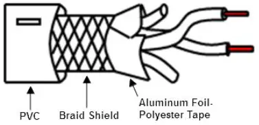 |
| Type | BC (Bare Copper) | |
| Insulation | PE (Polyethylene) | |
| Diameter(inch) | 0.035 | |
| Shield | Aluminum Foil-Polyester,
Tape/Braid Shield |
|
| Capacitance(pF/ft) | 8.5 | |
| Characteristic impedance(Ω) | 150Ω | |
Parts Name and Dimension (mm)
- This is the front part of the Module. Refer to each name when operating the system. For more information, refer to the user’s manual.
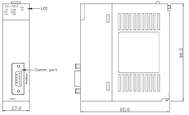
LED details
| Silk | Description | |
| RUN | On | Initialize complete and normal operation |
| Off | Fatal error | |
| I/F | Blink | Normal in interface status with CPU |
| Off | Error in interface status with CPU | |
|
HS |
On | Normal HS link communication status |
| Blink | Stop communication status/downloading Parameter in HS link enable | |
| Off | HS Link service disable status | |
|
P2P |
On | Normal P2P communication status |
| Blink | Stop communication status/downloading Parameter in P2P to enable | |
| Off | P2P disable status | |
| P-RUN | On | Normal communication |
| Off | Communication is stopped | |
| STATUS | On | System error |
| Off | Normal communication | |
|
ERR |
On | All slaves are eliminated |
| Blink | Some slaves are eliminated | |
| Off | Normal communication | |
|
CFG |
On | No network configuration for the Profibus-DP Master module |
| Blink | Downloading or uploading configuration parameters to the Master module | |
| Off | Network configuration is installed successfully | |
Installing Removing Modules
Here describes the method to attach each module to the base or remove it.
Installing module
- Insert a fixed projection of the lower part Of PLC into the module fixed hole of the base
- Slide the upper part of the module to fix it to the base, and then fit it to the base by using the module-fixed screw.
- Pull the upper part of the module to check if it is installed to the base completely.
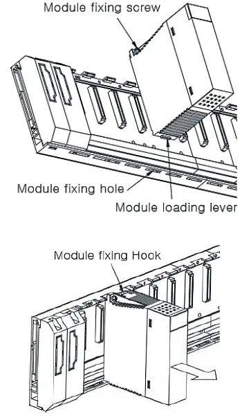
Removing module
- Loosen the fixed screws of the upper part of a module from the base
- By pressing the hook, pull the upper part of the module from the axis of the lower part of the module
- By lifting the module upward, remove the loading lever of the module from the fixing hole
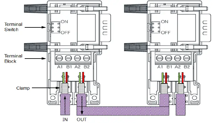
Wiring
Precaution for wiring
- Input line: The green line is connected to A1, the red line is connected to B1
- Output line: The green line is connected to A2, the red line is connected to B2
- Connect the shield to the clamp of the connector
- In case of installing the connector at the terminal, install the cable at A1, B1
- For more wiring information, refer to the user manual.
Warranty
- The warranty period is 36 months from the date of manufacture.
- The initial diagnosis of faults should be conducted by the user. However, upon request, LS ELECTRIC or its representative(s) can undertake this task for a fee. If the cause of the fault is found to be the responsibility of LS ELECTRIC, this service will be free of charge.
Exclusions from warranty
- Replacement of consumable and life-limited parts (e.g. relays, fuses, capacitors, batteries, LCDs, etc.)
- Failures or damages caused by improper conditions or handling outside those specified in the user manual
- Failures caused by external factors unrelated to the product
- Failures caused by modifications without LS ELECTRIC’s consent
- Use of the product in unintended ways
- Failures that cannot be predicted/solved by current scientific technology at the time of manufacture
- Failures due to external factors such as fire, abnormal voltage, or natural disasters
- Other cases for which LS ELECTRIC is not responsible
For detailed warranty information, please refer to the user’s manual.
The content of the installation guide is subject to change without notice for product performance improvement.
CONTACT
- LS ELECTRIC Co., Ltd. www.ls-electric.com 10310001626 V1.3 (2024.6)
- E-mail: automation@ls-electric.com
- Headquarters/Seoul Office Tel: 82-2-2034-4033,4888,4703
- LS ELECTRIC Shanghai Office (China) Tel: 86-21-5237-9977
- LS ELECTRIC (Wuxi) Co., Ltd. (Wuxi, China) Tel: 86-510-6851-6666
- LS-ELECTRIC Vietnam Co., Ltd. (Hanoi, Vietnam) Tel: 84-93-631-4099
- LS ELECTRIC Middle East FZE (Dubai, U.A.E.) Tel: 971-4-886-5360
- LS ELECTRIC Europe B.V. (Hoofddorf, Netherlands) Tel: 31-20-654-1424
- LS ELECTRIC Japan Co., Ltd. (Tokyo, Japan) Tel: 81-3-6268-8241
- LS ELECTRIC America Inc. (Chicago, USA) Tel: 1-800-891-2941
- Factory: 56, Samseong 4-gil, Mokcheon-eup, Dongnam-gu, Cheonan-si, Chungcheongnamdo, 31226, Korea

Documents / Resources
 |
XGT XGL-PMEB Programmable Logic Controller [pdf] Installation Guide XGK-28, XGL-PMEB, XGL-PMEB Programmable Logic Controller, XGL-PMEB, Programmable Logic Controller, Logic Controller, Controller |