![]()
Wireless Data Recorder
RTR505B
User’s Manual
RTR505B Wireless Data Recorder
Thank you for purchasing our product.
To ensure safe and proper operation, please read this guide thor-oughly before use.
Overview
RTR505B is a data logger designed to measure and record different items depending on the input module to be connected: temperature (Thermocouple, Pt), analog signal (4-20mA, DC voltage), and pulse.
Recorded data is then automatically collected by the Base Unit via wireless communication and downloaded for archive and analysis.
RTR505B requires a Base Unit to carry out wireless communication.
(Compatible Base Units: RTR500BC, RTR500BW, RTR500BM, RTR-500MBS-A, RTR-500DC, RTR-500, RTR-500NW/AW)
For the operation and configuration of the Base Unit, refer to the instruction manual attached to the Base Unit or the RTR500B Series Help available on T&D Website.
Wireless Data Recorder RTR505B is referred to as the “(data) logger” or “device” in this manual.
Package Contents
- RTR505B or RTR505BL (Large Battery Type)
- Lithium Battery LS14250 (or Large Capacity Battery Kit RTR-500B1 for L type model)
- Strap (Not included with L type model)
- Manual Set (Warranty Included)
Part Names

Input Modules (Sold Separately)
| Measurement Item | Input Module | LCD Displayed Items |
| Temperature (Type K, J, T, S) | Thermocouple Module (TCM-3010) | Measurement, Unit of Measurement, Sensor Type, Operational Status |
| Temperature (Pt100, Pt1000) | PT Module (PTM-3010) | Measurement, Unit of Measurement, Sensor Type, Operational Status |
| Voltage | Voltage Module (VIM-3010) | Measurement, Unit of Measurement, Operational Status |
| 4-20mA | 4-20mA Module (AIM-3010) | Measurement, Unit of Measurement, Operational Status |
| Pulse | Pulse Input Cable (PIC-3150) | Measurement, Unit of Measurement, Operational Status |
- Before using the pulse input cable, it is necessary to set the measurement item to “pulse type” in the Remote Unit Settings of the application.
- In order to change the measurement item, initialize the Remote Unit without connecting the input module and then redo the Remote Unit registration and settings.

Battery Installation
Recording starts automatically by inserting the battery with the default or previous settings.
 Default Settings
| Recording Mode | Endless |
| Recording Interval | 10 minutes |
| Recording Start Method | Immediate Start |
- Make sure to use the proper type and size screwdriver. (Phillips head #1 screwdriver is recommended.)
- Insert the supplied battery with the tube attached. When using a CR2 lithi- um battery, the tube is not necessary.
- Before closing the cover, check the rubber packing for dust or scratches, as they can reduce the water resistance of the rubber.
- Be sure to completely close the cover. Make sure not to over tighten the screws.
- Appropriate Tightening Torque: 20N·cm to 30N·cm (2Kgf·cm to 3Kgf·cm)
Battery Replacement
When it is time for the battery to be replaced, a battery warning mark will appear. Please change the battery as soon as possible if this mark appears.
![]() If you continue to use the logger without changing the battery, the current temperature and [bAtt] will be displayed alternately and wireless communication will stop. (Recording will continue.)
If you continue to use the logger without changing the battery, the current temperature and [bAtt] will be displayed alternately and wireless communication will stop. (Recording will continue.)
![]()
- If the battery is further left unchanged, the display will automatically shut off and all previously recorded data will be lost.
- Although the logger continues to work for a period after the battery has been removed, leaving the device without a battery until the LCD display goes blank will cause all recorded data to be lost.
- After the battery installation, the battery warning mark may not disappear from the logger’s LCD for 10 to 60 minutes. This is due to the characteristic of the lithium battery and is not a malfunction of the logger or the battery.
Remote Unit Registration and Settings
Via Software and Optical Communication
Connect the Base Unit to a PC with a USB cable, and place the data logger face down to align the communication areas as shown below. ![]() Via Mobile App and Bluetooth® Communication
Via Mobile App and Bluetooth® Communication
When the Base Unit is a RTR500BW or RTR500BM, it is possible to make Base Unit and Remote Unit settings from nearby mobile devices using Bluetooth.

Other Indications on Display
Logging Capacity FULL
![]() When Recording Mode has been set to “One Time” and the logger reaches its logging capacity of 16,000 readings, recording will automatically stop and in the LCD the measurement and the word [FULL] will alternately appear.
When Recording Mode has been set to “One Time” and the logger reaches its logging capacity of 16,000 readings, recording will automatically stop and in the LCD the measurement and the word [FULL] will alternately appear.
Estimation of time until [FULL] is displayed
| Rec Interval | 1 second | 30 seconds | 1 minute | 10 minutes | 60 minutes |
| Time Period | About 4 hours |
About 5 days | About 11 days |
About 111 days |
About 1 year and 10 months |
Data Transmission via Wireless Communication
![]() The measurement and the word [SEnd] will alternately appear when data is being sent via wireless communication to the Base Unit. Recording will continue during wireless transmission.
The measurement and the word [SEnd] will alternately appear when data is being sent via wireless communication to the Base Unit. Recording will continue during wireless transmission.
Input Module Unrecognized (factory default)
![]() This will appear if, after purchasing, the input module has never been connected to the logger. (No unit displayed)
This will appear if, after purchasing, the input module has never been connected to the logger. (No unit displayed)
Input Module Unconnected or Damaged
![]() This will appear if the device cannot confirm a connection with the input module after having recognized it. (Unit of Measurement displayed)
This will appear if the device cannot confirm a connection with the input module after having recognized it. (Unit of Measurement displayed)
• If nothing is displayed after reconnecting the module to the device, there is a possibility that the module or the device has been damaged.
Sensor Unconnected or Damaged
![]() This will be displayed when a sensor has not been connected to the module or the wire has been broken. Recording is in progress and so is battery consumption.
This will be displayed when a sensor has not been connected to the module or the wire has been broken. Recording is in progress and so is battery consumption.
• If nothing appears on display after reconnecting the sensor to the device, there is a possibility that the sensor or the device has been damaged.
Measurement Range Exceeded
![]() [OL] will appear if a measurement exceeds the measure ment range.
[OL] will appear if a measurement exceeds the measure ment range.
Display Range Exceeded
![]() When measuring voltage in mV range, the measurement in the LCD display will flash if it exceeds the display range of the device.
When measuring voltage in mV range, the measurement in the LCD display will flash if it exceeds the display range of the device.
Specifications
| Measurement Item | Temperature, Voltage, 4-20mA, or Pulse Count (*1) |
| Logging Capacity | 16,000 readings |
| Recording Interval | 1, 2, 5, 10, 15, 20, 30 sec. 1, 2, 5, 10, 15, 20, 30, 60 min. |
| Recording Mode(*2) | Endless (Overwrite oldest data when capacity is full) or One Time (Stop recording when capacity is full) |
| Communication Interfaces | Short Range Wireless Communication Frequency Range: 902 to 928MHz RF Power: 7mW Transmission Range: Approx. 150 meters (500 ft) if direct and unobstructed Bluetooth 4.2 (Bluetooth Low Energy) (*3) Optical Communication |
| Power | Lithium Battery LS14250 x 1 L Type: Large Capacity Battery Adaptor Kit (RTR-500B1) (*4) External Power Adaptor Kit RTR-500A2 |
| Battery Life (*5) | Approx. 10 months / L Type: About 4 year |
| Dimensions | H 62 mnn x W 47 mnn x D 19 mnn L Type: H 62 mm x W 47 mmx D 46.5 mm (excluding protrusions and Input Module) Antenna length: 24 mm |
| Weight | Approx. 50 g / L Type: Approx. 65 g |
| Operating Environment | -40 to 80°C -30 to 80°C during wireless communication |
| Waterproof Capacity | IP64: Splash proof (rated for use in daily life) (*6) |
| Compatible Base Units | RTR500BC, RTR500BW, RTR500BM RTR-500DC, RTR-500MBS-A, RTR-500NW/AW (*7)(*8) RTR-500 (*8) |
- Measurement item depends on the input module (sold separately).
- Only “Endless” is available when using the RTR500BW, RTR500BM, RTR-500NW/AW or RTR-500MBS-A as a Base Unit.
- Bluetooth is available when using the RTR500BW or RTR500BM as a Base Unit and making device settings in the mobile app (T&D 500B Utility).
- When using RTR-500B1 it is necessary to purchase Lithium Battery (LS26500). For details, contact your local authorized distributor.
- The listed battery life is based on the following usage conditions: Recording at 10 second (or longer) intervals, Current Readings Transmission every 10 minutes, and Recorded Data Transmission once a day. Battery life also varies depending on ambient temperature, radio environment, frequency of communication, etc.
- Input module (sold separately) is not water resistant.
- A firmware update is required to a RTR500B series compatible version.
- A software update is required to a RTR500B series compatible version.
The specifications listed above are subject to change without notice.
How to Read the LCD Display
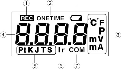
| 1 | [REC] Mark | Shows the recording status. ON: Recording in progress BLINKING: Waiting for programmed start OFF: Recording stopped |
| 2 | [ONETIME] Mark | Shows the recording mode. ON: One Time OFF: Endless |
| 3 | Battery Warning Mark | Indicates it is time for the battery to be replaced. |
| 4 | Measurement and Message Area | Measurements or operational messages are shown here. |
| 5 | Sensor Type | The type of sensor connected to or set in the logger is shown here. Thermocouple: Type K, J, T, S Platinum Thermal Resistance Sensor: Pt (Pt100), PtK (Pt1000) |
| 6 | [Ir] Mark | Indicates that the logger (Remote Unit) has not been registered to the Base Unit or the wireless communication is stopped (inactive radio). |
| 7 | [COM] Mark | Indicates that the device is in Bluetooth communication. |
| 8 | Unit of Measurement | Shows the unit of measurement. |
Basic Measurement Display
Display varies depending upon the input module connected.
Temperature (Thermocouple / Pt100 / Pt1000) ![]() Temperature measurement (Unit: °F / °C) will be displayed. Sensor type will be displayed under the measurement; the factory default setting is Type K and Pt (Pt100). The sensor type setting can be changed in the Remote Unit Settings of the application.
Temperature measurement (Unit: °F / °C) will be displayed. Sensor type will be displayed under the measurement; the factory default setting is Type K and Pt (Pt100). The sensor type setting can be changed in the Remote Unit Settings of the application.
Voltage
![]() Voltage measurement (Unit: V / mV) will be displayed. Due to the wide measurement range, the device has been set by default to adjust the decimal point automatically to display the measurement in V. The unit of display can be changed in the Remote Unit Settings of the application.
Voltage measurement (Unit: V / mV) will be displayed. Due to the wide measurement range, the device has been set by default to adjust the decimal point automatically to display the measurement in V. The unit of display can be changed in the Remote Unit Settings of the application.
4-20mA
![]() 4-20mA measurement (Unit: mA) will be displayed.
4-20mA measurement (Unit: mA) will be displayed.
Pulse
There are two display methods for the pulse measurement. The display method can be changed in the Remote Unit Settings of the application.
![]() Pulse Rate (Max: 61439)
Pulse Rate (Max: 61439)
The most recent pulse count (Unit: P) for the recording interval period will be displayed. The display will be refreshed every one-sixtieth of the recording interval (at minimum of every one second). 50,500 pulse count will be displayed as [50.50P] with “K“ below the measurement value. The display is in units of 10 pulses. ![]() Total Pulse Count
Total Pulse Count
The cumulative number of pulses (Unit: P) will be displayed from 0 to 9999. The displayed count will be refreshed every one second, and upon exceeding 9999, the count will start over again from 0.
![]() Rio Refugio 9648 – Parque de Negocios ENEA, Pudahuel, Santiago ~ CHILE
Rio Refugio 9648 – Parque de Negocios ENEA, Pudahuel, Santiago ~ CHILE
Tel. +56 2 28988221
• www.yalitech.cl
![]() tandd.com
tandd.com
© Copyright T&D Corporation. All rights reserved.
2021.11 16508210006 (2nd Edition) Printed on recycled paper.
Documents / Resources
 |
T D RTR505B Wireless Data Recorder [pdf] User Manual RTR505B Wireless Data Recorder, RTR505B, Wireless Data Recorder, Wireless Recorder, RTR505B Data Recorder, Data Recorder, Recorder |


