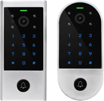
Smart Video Intercom Access

![]()
![]()
User Manual
Introduction
The device is Touch Key Access Controller with WiFi-enabled Intercom. People can install the APP for intercom with their smart phone, and program the access controller by touch key.
It is compatible with both iOS (7.0 above) and Android (4.3 above).
Features:
Intercom
> 2.4G WiFi connection
> Android and iOS available
> Full duplex voice intercom
> 2MP+wide angle camera and night vision
> Support TF card with unlimited capacity
> Support motion detection, playback, take picture/video, unlock remotely
Access Control
> Touch key with one relay, 1000 users (988 common+2 panic+10 visitor)
> PIN Length: 4~6 digits
> EM card, Mifare card optional
> Wiegand 26~44 bits input & output
> Can be used as Wiegand reader with LED & buzzer
> User data can be transferred
> 2 devices can be interlocked for 2 doors
Specification:
| Video Intercom | Network | 2.4G WiFi connection |
| Pixel | 2.0Mpx (1080P) | |
| Visual Angle | Horizontal 140° wide angle | |
| Night Vision | IR-CUT (Colorful at daytime, black and white at night) | |
| Extended Memory | TF card with unlimited capacity | |
| Intercom | Full duplex voice intercom | |
| Other Functions | Motion detection; Playback; Take picture/video; Unlock remotely | |
| Access Control | User Capacity Common User Visitor User Panic User |
1000 988 10 2 |
| PIN Length | 4~6 digits | |
| Proximity Card Reader Radio Technology Read Range |
EM or Mifare 125KHz/13.56MHz 2~6cm |
|
| Wiring Connections | Relay output, exit button, alarm, door contact, Wiegand input/output | |
| Relay Adjustable Relay Output Time Lock Output Load |
One (NO, NC, Common) 0~99 Seconds (5 seconds default) 2 Amp Maximum |
|
| Wiegand Interface
PIN Output |
EM card version: Wiegand 26~44 bits input & output (Factory default: Wiegand 26bits) Mifare card version: Wiegand 26~44 bits input & output (Factory default: Wiegand 34bits) 4 bits, 8 bits (ASCII), 10 digits Virtual Number (Factory default: 4bits) |
|
| Electric | Operating Voltage Idle Current Active Current |
DC 12V <150mA <250mA |
| Environment Operating Temperature Operating Humidity |
Indoor -20°C ~ 60°C (-4°F ~ 140°F) 0%RH ~ 86%RH |
|
| Physical Color DimensionsUnit Weight Shipping Weight |
Zinc-Alloy Sliver & Black L145 x W68 x D25(mm) Rectangle L149 x W70 x D25(mm) Ellipse 450g (Rectangle) / 400g (Ellipse) 550g (Rectangle) / 500g (Ellipse) |
Carton Inventory:

![]() Diode IN4004 (For relay circuit protection)
Diode IN4004 (For relay circuit protection)
![]() Wall Anchors
Wall Anchors
![]() Self Tapping Screws: Φ4*25mm
Self Tapping Screws: Φ4*25mm
 Screw Driver
 Master Card
Installation
> Remove the back cover from the unit
> Drill 2 holes(A,C) on the wall for the screws and one hole for the cable
> Knock the supplied rubber bungs to the screw holes(A,C)
> Fix the back cover firmly on the wall with 4 flat head screws
> Thread the cable through the cable hole(B)
> Attach the unit to the back cover


Wiring
| Wire Color | Function |
Notes |
| Basic Standalone Wiring | ||
| Red | DC + | 12V DC Power Input |
| Black | GND | Negative Pole of DC Power Input |
| Blue | Relay NO | Normally Open Relay Output (install diode provided) |
| Purple | Relay Common | Common Connection for Relay Output |
| Orange | Relay NC | Normally Closed Relay Output (Install diode provided) |
| Yellow | OPEN | Request to Exit(REX) Input |
| Pass-Through Wiring (Wiegand Reader or Controller) | ||
| Green | Data 0 | Wiegand Output (Pass-through) Data 0 |
| White | Data 1 | Wiegand Output (Pass-through) Data 1 |
| Advanced Input and Output Features | ||
| Grey | Alarm Output | Negative contact for Alarm |
| Brown | Contact Input | Door/Gate Contact Input (Normally Closed) |
Sound and Light Indication
|
Operation Status |
LED |
Buzzer |
| Stand by | Red light bright | – |
| Enter into programming mode | Red light shines | One beep |
| In the programming mode | Orange light bright | One beep |
| Operation error | – | Three beeps |
| Exit from the Programming mode | Red light bright | One beep |
| Open lock | Green light bright | One beep |
| Alarm | Red light Shines quickly | Beeps |
APP Operation
Here are just a few steps to get you started.
1) Free APP Downloading
Search TuyaSmart or Smartlife on Google Play or APP Store
![]()

2) Make sure WiFi works on your mobile phone.
1. Register & Login
(Make sure the registered email is legal and valid, so that you can recover your password once forgotten. Mobile Number is for China Mobile ONLY)

You will get a verification code in your mail box.
2. Add Device
You can add device by clicking ‘Add Device’ or clicking ‘+’ on the top.
Before Adding the device, please make sure it is in adding mode (Door bell LED flashes slowly).
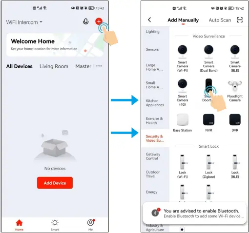

Note: To better manage the devices and family members, you will need to create a HOME before you begin to manage this device.

![]() Intercom voice ON/OFF
Intercom voice ON/OFF
![]() Full screen
Full screen
![]() Take a picture
Take a picture
![]() Intercom ON/OFF
Intercom ON/OFF
![]() Take a Video
Take a Video
![]() Check the Alarm video record (To use this function, must insert a TF card in the device)
Check the Alarm video record (To use this function, must insert a TF card in the device)
![]() Check the picture or video
Check the picture or video
![]() Change the theme color
Change the theme color
![]() Adjust the volume of device
Adjust the volume of device
![]() Motion detection ON/OFF
Motion detection ON/OFF
![]() Unlock the door
Unlock the door
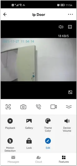
3. Operation

(1) Revise device name and location
(2) Check IP address, ID and time zone of device
(3) Configure one or more devices’ automation
(4) Door bell LED ON/OFF; Flip screen
(5) Adjust device volume
(6) Motion detection ON/OFF, set the detection sensitivity, set alarm timer
(7) Check the capacity (Total/Used/Remaining) of TF card, and format TF card
(8) Value-added Service
(9) If turn on it, a notification will be sent after device stayed offline in 30 minutes.
(10) Check the FAQ related to device
(11) Share the device by Tuya account, message, email, or chat APPs.(Shared Users can’t unlock the door and set the device, only Family Members can unlock the door.)
(12) Add a shortcut to your home screen.
(13) Restart the device
(14) Remove the device
4. Intercom Calling and Motion Detection
1. The APP is online when intercom calling

2. The mobile is standby when intercom calling or detecting motion
2.1 Click “You have a visitor” message into the intercom interface
2.2 Click “Motion detected” message into alarm record interface

Note: There are two ways to check the alarm record
- Click the Message button in the intercom interface
- Check in the Message Center

Keypad Operation
Basic Configure:
|
Function |
Keystroke Steps |
Notes |
| Set master code | * (Master Code) # 0 (New Code) # (Repeat New Code) # | Default Master Code is 123456 |
| Standalone/Controller mode | * (Master Code) # 7 7 # | To put the device back to its default factory working mode |
| Wiegand reader mode | * (Master Code) # 7 8 # | Wiegand output |
| Exit | * | Press * to exit programming |
Standalone/Controller Mode
Connection Diagram
Common Power Supply

Attention:
Install a 1N4004 or equivalent diode is needed when use a common power supply, or the keypad might be damaged. (1 N4004 is included in the packing)
Access Control Power Supply

Users Management:
|
Function |
Keystroke Steps |
Notes |
| Add common card user | * (Master Code) # 1 (Read card) / (Input 8/10 digits card number) # | Using auto ID, the cards can be added continuously |
| * (Master Code) # 1 (User ID) # (Read card) / (Input 8/10 digits card number) # | Select specific ID, ID number: 0~987 |
|
| * (Master Code) # 1 (User ID) # (Card quantity) # (The first card 8/10 digits number) # | Select specific ID, ID number: 0~987 |
|
| Add common PIN user | * (Master Code) # 1 (PIN) # | Using auto ID, the PINs can be added continuously |
| * (Master Code) #1 (User ID) # (PIN) # | Select specific ID, ID number: 0~987 | |
| Add panic user | * (Master Code) # 1 (User ID) # (Read card / Input 8/10 digits card number / PIN) # | User ID number is 988,989; PIN length: 4-6 digits except 8888 |
| Add visitor user | * (Master Code) # 1 (User ID) # (0~9) # (Read card / Input 8/10 digits card number / PIN) # | (0~9) means times of usage, 0=10 times, after the certain number of times, the card/PIN become invalid automatically ID number: 990~999 |
| Change PIN | * (User ID) # (Old PIN) # (New PIN) # (Repeat new PIN) # | PIN length: 4-6 digits except 8888 |
| Change PIN of Card + PIN access mode | * (Read card) (Old PIN) # (New PIN) # (Repeat new PIN) # | There will auto allocate PIN (8888) to cards when adding |
| Delete user | * (Master Code) # 2 (Read card) / (Input PIN) # | Delete user by card/PIN, the users can be deleted continuously |
| * (Master Code) # 2 (User ID) # | Delete user by ID number | |
| * (Master Code) # 2 (Input 8/10 digits card number) # | Delete user by card number | |
| * (Master Code) # 2 (Master Code) # | Delete all users | |
| Exit | * | Press *to exit programming |
Tips for PIN Security (Only valid for 6 digits PIN):
For higher security we allow you to hide your correct PIN with other numbers up to a max of 10 digits.
Example PIN: 123434
You could use **(123434)** or ** (123434)
(“*” can be any numbers from 0~9)
Set Access Mode:
|
Function |
Keystroke Steps |
Notes |
| Card access | * (Master Code) # 4 0 # | Entry by card only |
| PIN access | * (Master Code) # 4 1 # | Entry by PIN only |
| Card + PIN access | * (Master Code) # 4 2 # | Entry by card + PIN |
| Card or PIN access | * (Master Code) # 4 3 # | Entry by card or PIN (default) |
| Multi user access | * (Master Code) # 4 3 (2~9) # | Only after 2~9 valid users, the door can be opened. The interval time of reading can’t exceed 5 seconds |
| Exit | * | Press* to exit programming |
Operation Setting:
|
Function |
Keystroke Steps |
Notes |
| Relay time setting | * (Master Code) # 3 (1~99) # | Time range: 1~99s (default is 5 seconds) |
| Relay toggle mode | * (Master Code) # 3 0 # | Set the relay to ON/OFF toggle mode |
| Strike-Out OFF | * (Master Code) # 6 0 # | Normal mode (default) |
| Strike-Out ON | * (Master Code) # 6 1 # | Access will be denied for 10 minutes after 10 failed entry attempts.(Exit button is still workable) |
| Strike-Out ON (Alarm) | * (Master Code) # 6 2 # | It will alarm after 10 failed entry attempts. Enter any valid card / PIN # (user or master) to silence |
| Disable door open detection | * (Master Code) # 6 3 # | Normal mode (default) |
| Enable door open detection(Request to connect magnetic contact) | * (Master Code) # 6 4 # | Door open too long (1 minutes) or door forced open detection. Enter any valid card / PIN # (user or master) to silence |
| Alarm time | * (Master Code) # 5 (0~3) # | Time range: 0~3 minutes, default is 1 minute |
| Disable sound | * (Master Code) # 7 0 # | Sound closed |
| Enable sound | * (Master Code) # 7 1 # | Sound activated (default) |
| LED always OFF | * (Master Code) # 7 2 # | LED is off under standby |
| LED always ON | * (Master Code) # 7 3 # | LED is on under standby (default) |
| Keypad backlit always OFF | * (Master Code) # 7 4 # | Turn off keypad backlit |
| Keypad backlit always ON | * (Master Code) # 7 5 # | Turn on keypad backlit |
| Keypad backlit automatic OFF | * (Master Code) # 7 6 # | Automatic off after 20s, it will go ON by pressing any key (this key isn’t taken into consideration) (default) |
| Set Wiegand input | * (Master Code) # 8 (26~44) # | EM version default is 26 bits Mifare version default is 34 bits |
| Disable parity bits | * (Master Code) # 8 0 # | Disable parity bits |
| Enable parity bits | * (Master Code) # 8 1 # | Enable parity bits (default) |
| PIN input bits | * (Master Code) # 8 (4 or 8 or 10) # | 4=4 bits, 8=8 bits(ASCII), 10=10 digits virtual number |
| Exit | * | Press * to exit programming |
Note: For connecting Wiegand reader with 32, 40 bits input, need disable parity bits
Master Card Usage
| Using Master Card to add and delete users | |
| Add Card/ PIN Users |
|
| Delete Card/ PIN Users |
|
Users Operation & Reset to Factory Default
> Open the door: Read valid user card or input valid user PIN #
> Remove Alarm: Enter Master Code # or Master Card or valid user card/PIN
> To reset to factory default & Add Master Card: Power off, press the Exit Button, hold it and power on, there will be two beeps, then release the exit button, the LED light turns into yellow, then read any 125KHz EM card/13.56MHz Mifare card, the LED will turn into red, means reset to factory default successfully. Of the card reading, it is the Master Card.
Remarks:
(1) If no Master Card added, must press the Exit Button for at least 5 seconds before release.(this will make the previous registered Master Card invalid)
(2) Reset to factory default, the user’s information is still retained.
Wiegand Reader Mode
Connection Diagram

- Access Controller
Set Wiegand Output:
|
Function |
Keystroke Steps |
Notes |
| Set Wiegand output | * (Master Code) # 8 (26~44) # | EM version default is 26bits Mifare version default is 34 bits |
| Disable parity bits | * (Master Code) # 8 0 # | Disable parity bits |
| Enable parity bits | * (Master Code) # 8 1 # | Enable parity bits (default) |
| PIN output bits | * (Master Code) # 8 (4 or 8 or 10) # | 4=4 bits, 8=8 bits(ASCII), 10=10 digits virtual number |
| Exit | * | Press * to exit programming |
Note: For connecting Wiegand controller with 32, 40 bits input, need disable parity bits
Advanced Application
User Information Transfer (Valid for Card / PIN Users)
The device supports the User Information Transfer function, and the enrolled user (cards, PINs) can be transferred from one (let’s name it Master Unit) to another (let’s name it Accept Unit).
Connection Diagram:

- The Device
Interlock
Remarks: The Door Contact must be installed and connected as the diagram.
Let’s name the two Devices as “A “and “B” for two doors “1” and “2”
Connection Diagram:

- The Device
If enable interlock, when and only door 2 is closed, the user can read the valid fingerprint/ card or input PIN on Reader A, door 1 will open; then when and only door 1 closed, read valid fingerprint/card or input PIN on Reader B, door 2 will open.
Advanced Setting:
|
Function |
Keystroke Steps |
Notes |
| Transfer users | * (Master Code) # 9 8 # | The master code of two devices must be same. Program on Master Units only. |
| Disable interlock | * (Master Code) # 9 0 # | Disable interlock (default) |
| Enable interlock | * (Master Code) # 9 1 # | The users in two devices must completed same |
| Exit | * | Press * to exit programming |
|
Simplified Instruction |
|
| Function Description | Operation |
| Enter the Programming Mode | * – Master Code – # then you can do the programming (123456 is the factory default master code) |
| Change the Master Code | 0 – New Code – # – Repeat the New Code -# (code: 6 digits) |
| Add Card User | 1 – Read Card – # (can add cards continuously) |
| Add PIN User | 1 – PIN -# (The PIN is any 4~6 digits except 8888 which is reserved) |
| Delete User | 2 – Read Card – # 2 – PIN – # |
| Exit from the Programming Mode | * |
| How to release the door | |
| Card User | Read Card |
| PIN User | Input PIN # |
| Mobile User | By Mobile |


140° Wide Angle Touch Button Multi-users


Max 2.0Mpx Support TF Card Monitoring


Video Talking Night Vision Remote Unlocking
Documents / Resources
 |
Secukey Vcontrol 1 Smart Video Intercom Access [pdf] User Manual Vcontrol 1 Smart Video Intercom Access, Vcontrol 1, Vcontrol 1 Intercom Access, Smart Video Intercom Access, Intercom Access, Smart Video Intercom, Video Intercom, Smart Intercom, Intercom |


