![]() www.pyramid.tech
www.pyramid.tech
FX4
FX4 Programmer Manual
Document ID: 2711715845
Version: v3
FX4 Programmer
Document ID: 2711715845
FX4 – FX4 Programmer Manual
![]() Document ID: 2711650310
Document ID: 2711650310
| Author | Matthew Nichols |
| Owner | Project Lead |
| Purpose | Explain the programming concepts necessary to use the API and extend the product through external applications. |
| Scope | FX4 related programming concepts. |
| Intended Audience | Software developers interested in using the product. |
| Process | https://pyramidtc.atlassian.net/wiki/pages/createpage.action? spaceKey=PQ&title=Standard%20Manual%20Creation%20Process |
| Training | NOT APPLICABLE |
Version Control
| Version | Description | Saved by | Saved on | Status |
| v3 | Added a simple overview and more examples. | Matthew Nichols | Mar 6, 2025 10:29 PM | APPROVED |
| v2 | Added digital IO interfaces and references back to IGX. | Matthew Nichols | May 3, 2024 7:39 PM | APPROVED |
| v1 | Initial release, still a work in progress. | Matthew Nichols | Feb 21, 2024 11:25 PM | APPROVED |
![]() Document Control Not Reviewed
Document Control Not Reviewed
Current document version: v.1
No reviewers assigned.
1.1 Signatures
for most recent document version
Friday, Mar 7, 2025, 10:33 PM UTC
Matthew Nichols signed ; meaning: Review
References
| Document | Document ID | Author | Version |
| IGX – Programmer Manual | 2439249921 | Matthew Nichols | 1 |
FX4 Programming Overview
The FX4 processor runs on an environment called IGX, which is built on the QNX high-reliability realtime operating system from BlackBerry (QNX Website¹). IGX provides a flexible and comprehensive application programming interface (API) for users who want to write their own host computer software.
The IGX environment is shared across other Pyramid products, allowing software solutions developed for one product to be easily transferred to others.
Programmers can refer to the complete documentation for IGX available on the Pyramid website at: IGX | Modern Modular Control System Framework for Web-enabled Applications²
This section provides an introduction to testing two of the API methods: HTTP using JSON format and EPICS. For simplicity, Python (Python Website³) is used as an example host computer language, which is accessible and easy to use for non-professional programmers.
3.1 Using Python and HTTP
As an example, assume you want to read the sum of the measured currents with Python. You need the URL for that particular IO. The FX4 web GUI provides an easy way to find this: simply right-click in the field and select ‘Copy HTTP URL’ to copy the string to the clipboard.
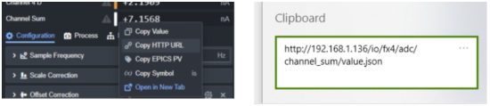
Now you can use Python to test connectivity to user software via HTTP and JSON. You may need to import the requests and json libraries to handle the HTTP requests and data parsing.
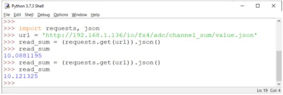 1 Simple Python HTTP Example
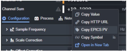
3.2 Using EPICS
The process for connecting the FX4 through EPICS (Experimental Physics and Industrial Control System) is similar. EPICS is a set of software tools and applications used to develop and implement distributed control systems, widely used in scientific facilities.
- Get the EPICS process variable (PV) name for the desired IO.
- Import the EPICS library and read the value.
 2 Get EPICS PV Name
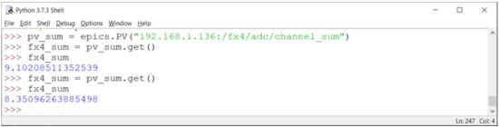 3 Simple Python EPICS Example
Additionally, Pyramid created a utility (EPICS Connect⁴) that allows you to monitor EPICS process variables in real-time. This tool is helpful to confirm if the EPICS PV name is correct and the FX4 is serving the PV correctly on your network.
 4 PTC EPICS Connect
FX4 Programming API
The concepts and methods described in this manual build on the concepts established in the IGX – Programmer Manual. Please see that document for explanation and examples of how basic IGX programming and interfaces work. This manual will only cover the device-specific IO and functionality that is unique to the FX4.
4.1 Analog Input IO
These IO relate to configuring and collecting data on the analog current inputs of the FX4. The units of the channel inputs are based on the user configurable setting called “Sample Units”, valid options include pA, nA, uA, mA, and A.
All 4 channels use the same interface IO and are independently controlled. Replace channel_x with channel_1 , channel_2 , channel_3 , or channel_4 respectively.
| IO Path | Description |
| /fx4/adc/channel_x | READONLY NUMBER Measured current input. |
| /fx4/adc/channel_x/scalar | NUMBER Simple unitless scalar applied to the channel, 1 by default. |
| /fx4/adc/channel_x/zero_offset | NUMBER Current offset in nA for the channel. |
The following IO are not channel independent and are applied to all channels simultaneously.
| IO Path | Description |
| /fx4/channel_sum | READONLY NUMBER Sum of the current input channels. |
| /fx4/adc_unit | STRING Sets the current user units for each channel and sum. Options: “pa”, “na”, “ua”, “ma”, “a” |
| /fx4/range | STRING Sets the current input range. See GUI for how each range code corresponds to the maximum current input limits and BW. Options: “0”, “1”, “2”, “3”, “4”, “5”, “6”, “7” |
| /fx4/adc/sample_frequency | NUMBER The frequency in Hz that sample data will be averaged to. This controls the signal-to-noise and data rate for all channels. |
| /fx4/adc/conversion_frequency | NUMBER The frequency in Hz that the ADC will convert analog to digital values at. By default, this is 100kHz, and you will only rarely need to change this value. |
| /fx4/adc/offset_correction | READONLY NUMBER Sum of all channel’s current offsets. |
4.2 Analog Output IO
These IO relate to the configuration of the general-purpose analog outputs of the FX4 found under the analog inputs on the front panel. All 4 channels use the same interface IO and are independently controlled. Replace channel_x with channel_1 , channel_2 , channel_3 , or channel_4 respectively.
| IO Path | Description |
| /fx4/dac /channel_x | NUMBER Command voltage output. This value can only be written to when output mode is set to manual. |
| /fx4/dac/channel_x/readback | READONLY NUMBER Measured voltage output. This is most helpful when using expression output mode. |
| /fx4/dac/channel_x/output_mode | STRING Sets the output mode for the channel. Options: “manual”, “expression”, “process_control” |
| /fx4/dac/channel _ x/slew_control_enable | BOOL Enables or disables slew rate limiting. |
| /fx4/dac/channel_ x/slew_rate | NUMBER Slew rate in V/s for the channel. |
| /fx4/dac/channel_x/upper_limit | NUMBER The maximum allowed command voltage for the channel. Applies to all operation modes. |
| /fx4/dac/channel _ x/lower_limit | NUMBER The minimum allowed command voltage for the channel. Applies to all operation modes. |
| /fx4/dac/channel _ x/ output _ expression | STRING Sets the expression string used by the channel when it is in the expression output mode. |
| /fx4/dac/channel _ x/reset_button | BUTTON Resets the command voltage to 0. |
4.3 Digital Input and Outputs
These IO relate to controlling the various general purpose digital inputs and outputs found on the FX4.
| IO Path | Description |
| /fx4/fr1 | READONLY BOOL Fiber receiver 1. |
| /fx4/ft1 | BOOL Fiber transmitter 1. |
| /fx4/fr2 | READONLY BOOL Fiber receiver 2. |
| /fx4/ft2 | BOOL Fiber transmitter 2. |
| /fx4/fr3 | READONLY BOOL Fiber receiver 3. |
| /fx4/ft3 | BOOL Fiber transmitter 3. |
| /fx4/digital_expansion/d1 | BOOL D1 bidirectional digital expansion IO. |
| /fx4/digital_expansion/d2 | BOOL D2 bidirectional digital expansion IO. |
| /fx4/digital_expansion/d3 | BOOL D3 bidirectional digital expansion IO. |
| /fx4/digital_expansion/d4 | BOOL D4 bidirectional digital expansion IO. |
4.3.1 Digital IO Configuration
All digitals have child IO for configuring their behavior including an operating mode which controls how that digital will operate. Each digital will have a different set of available options. See the GUI for details on what options are available for what IO.
| Child IO Path | Description |
| …/mode | STRING Operation mode for the digital. Options: “input“, “output”, “pwm”, “timer”, “encoder”, “capture”, “uart_rx”, “uart_tx”, “can_rx”, “can_tx”, “pru_input”, or “pru_output” |
| …/process_signal | STRING The process control signal name, if there is one. |
| …/pull_mode | STRING Pull up/down mode for a digital input. Options: “up“, “down”, or “disable” |
4.4 Relay Control
Both relays are independently controlled and share the same type of interface. Replace relay_x with relay_a or relay_b respectively.
| IO Path | Description |
| /fx4/relay _ x/permit / user _ command | BOOL Commands the relay open or closed. A true command will try to close the relay if the interlocks are granted, and false command will always open the relay. |
| /fx4/relay _ x/state | READONLY STRING The current state of the relay. Locked relays are open but cannot be closed due to an interlock. States: “opened”, “closed”, or “locked” |
| /fx4/relay _ x/automatically _ close | BOOL When set to true, the relay will automatically close when the interlocks are granted. False by default. |
| /fx4/relay _ x/ cycle _ count | READONLY NUMBER The number of relay cycles since the last reset. Useful for tracking relay lifetime. |
4.5 High Voltage Module
See the IGX – Programmer Manual for details on the FX4 high voltage interface. The component parent path is /fx4/high_votlage .
4.6 Dose Controller
See the IGX – Programmer Manual for details on the FX4 dose controller interface. The component parent path is /fx4/dose_controller .
FX4 Python Examples
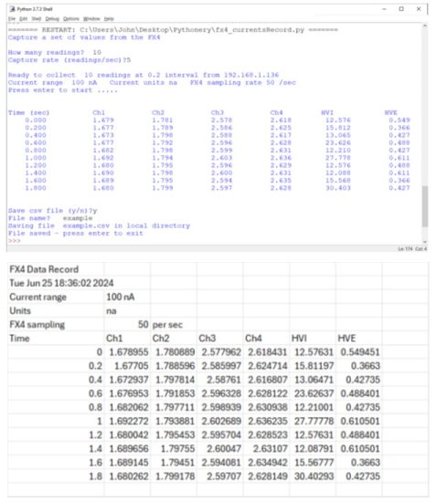
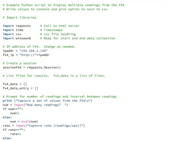
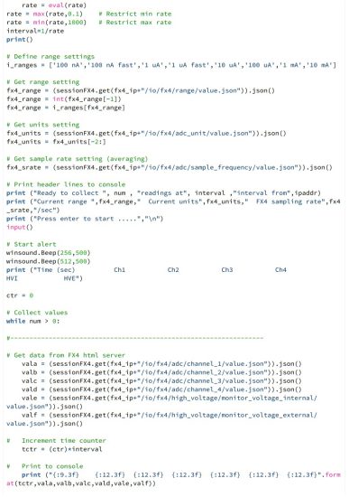
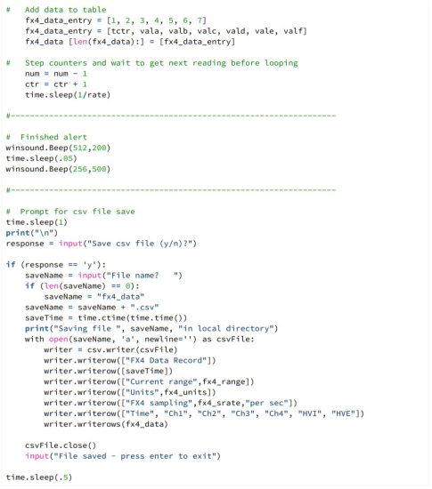
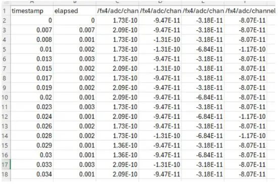
5.1 Data Logger using HTTP
This example demonstrates how to capture a number of readings and save them to a CSV file. By choosing a long delay between readings, you can perform long-term data logging even if the FX4 sampling rate is set higher. This allows you to continuously collect and store measurements over extended periods without overwhelming the system, ensuring that data is captured at intervals suitable for your analysis. The delay between readings helps regulate the pace at which data is logged, allowing for efficient storage and reducing the risk of missing data points while still benefiting from high-speed sampling for real-time measurements.
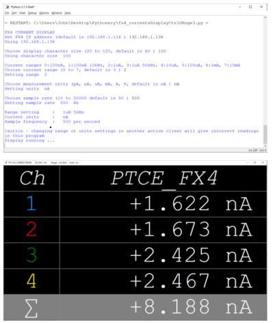
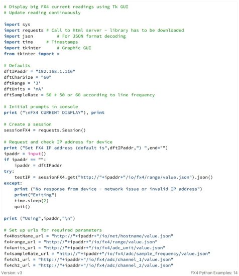
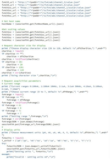
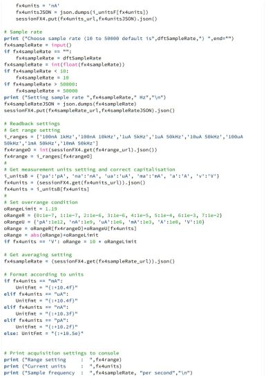
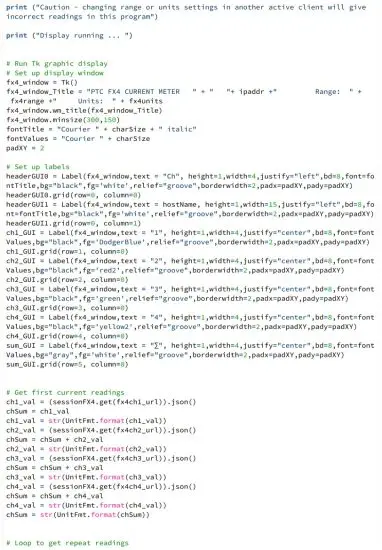
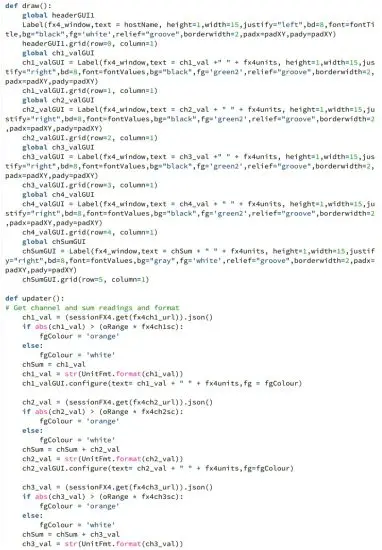
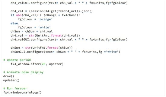
5.2 Simple Python GUI
The second example uses the Tkinter GUI tool, which is built for Python, to create a display of the measured currents. This interface allows you to visualize the current readings in a user-friendly graphical format. The display can be resized to make it large enough to read from across a room, making it ideal for scenarios where real-time monitoring is needed in larger spaces. Tkinter provides an easy way to create interactive interfaces, and by integrating it with the FX4, you can quickly build a visual display of the measured currents that can be customized to fit your specific needs.
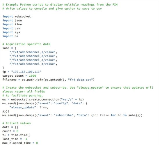
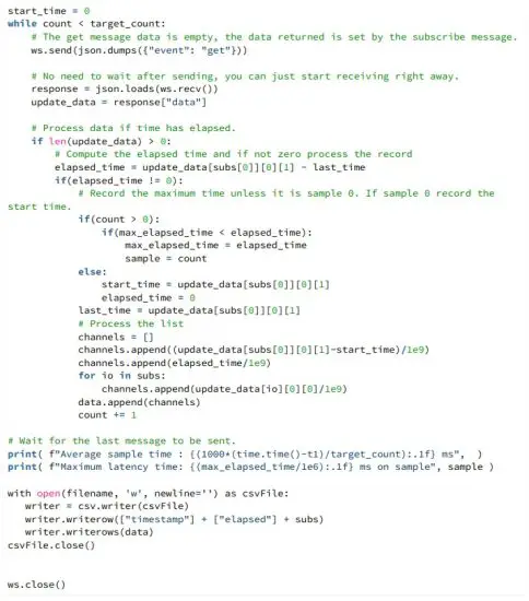
5.3 Simple WebSockets Example
This example demonstrates the WebSockets interface, which is the preferred method for reading data from the FX4 when maximum bandwidth is required. WebSockets provide a real-time, full-duplex communication channel, allowing for faster and more efficient data transfer compared to other methods.
The example reads a series of samples, reports the average time per sample and maximum latency, and saves the data to a CSV file for later analysis. This setup allows for efficient real-time monitoring and easy data storage for post-processing.
The specific performance that can be achieved with WebSockets depends on the reliability of your Ethernet interface and the relative priority of your application. For optimal results, ensure that your network is stable and that the FX4’s data transmission is prioritized if necessary.
Version: v3
FX4 Python Examples: 21
Documents / Resources
 |
PYRAMID FX4 Programmer [pdf] Instruction Manual FX4 Programmer, FX4, Programmer |