![]() ST9101
ST9101
User Guide
ST9100 Dual Mode Terminal

CONTACTAND LEGAL INFORMATION
Visit ORBCOMM Online
www.ORBCOMM.com
Contact Support
Email: partner-support@orbcomm.com
Head Office: 395 W Passaic Street, Suite 325, Rochelle Park, NJ 07662 USA
Export Control Statement
Thecontentsofthisdocument, in wholeor in part,shallnotbe exported fromthe United States, whichexport shall include, but not be limited to, transmittal to any non-U.S. citizen wherever said person is located, except in accordance with all United States laws and regulations relating to exports and to all administrative acts of the U.S. Government pursuant to such laws and regulations. Diversion, re-export or transshipment of the contents of this document, in whole or in part, contrary to U.S. law is also strictly prohibited.
Trademark Notice
The ORBCOMM name and the ORBCOMM logo are registered trademarks owned by ORBCOMM LLC or its affiliated companies.
Other trademarks, trade names, and logos are those of their respective owners.
PREFACE
Purpose
This guide contains product information for the ST9101. The intended audiences for this guide include field support personnel, product evaluators, and certified third-party personnel. It is particularly intended for personnel who are responsible for system installation and activation.
Notation
Hardware components and hardware labels in this document might not be exactly as shown and are subject to change without notice.
CAUTION: This safety symbol warns of possible hazards to personnel, equipment, or both. It includes hazards that will or can cause personal injury, property damage, or death if the hazard is not avoided.
Note: A note indicates information with no potential hazard. A note indicates points of interest or provides supplementary information about a feature or task. Numbered lists indicate a series of steps required to complete a task or function. Bulleted lists highlight information where order or sequence is not crucial.
Battery Safety Warnings
CAUTION: Always follow local disposal guidelines to properly dispose of the Lithium-ion battery and the device.
CAUTION: DO NOT throw the internal battery or the device into fire.
CAUTION: DO NOT short circuit or expose the battery to temperatures above the maximum rated temperature.
CAUTION: Store in a cool, well-ventilated area. Elevated temperatures will result in shortened battery life.
CAUTION: DO NOT replace the battery. Changing the battery without ORBCOMM’s permission could violate regulatory conformity.
PRODUCT OVERVIEW
The ST9101 (part number ST9101-F01) is a flexible, robust, and programmable dual mode satellite-cellular terminal. It is ideal for remotely monitoring and controlling fixed and portable assets in industries as diverse as transportation, oil and gas, utilities, maritime and more. The versatile, environmentally sealed ST 9101 is ideal for rugged environments in the world’s most remote areas. It offers a satellite antenna (standard antenna part number ST101599-APA or low elevation antenna part number ST101600-APA) and a cellular antenna (part number ST101561-001).
 The transceiver’s built-in programmability allows it to work as a standalone data-messaging transceiver, with built-in I/O data collection and processing capabilities. Feature-rich software tools make programming easy and shorten the design and testing time. The transceiver can also be configured with terminal apps. Terminal apps are configurable device-level applications that include specific feature sets that are implemented by ORBCOMM.
SPECIFICATIONS
2.1.Temperature
| Parameter | Value |
| perating Temperature Range | -40° to +85°C (-40°F to +185°F) |
| Recommended Storage Temperature Range | -20° to +35°C (-4°F to +95°F) |
| Transceiver with Internal Backup Battery Charging TemperatureRange | 0°C to +45°C (32°F to +113°F) |
| Transceiver with Internal Backup Battery Discharge Temperature Range | -20°Cto+75°C (-4°F to+167°F) |
| Transceiver with Internal Backup Battery Storage Temperature Range ≤ 1 month ≤ 3 months ≤ 1 year Ideal for long-term storage |
-20°C to +45°C (-4°F to +113°F) -20°C to +35°C (-4°F to +95°F) 0°C to +30°C (32°F to +86°F) 10°C to +25°C (60±25% R.H.), (50°F to +77°F) |
2.2. Input Range
CAUTION: An external 5 A slow blow fuse must be added in series with the external voltage wire. Power Supply Voltage: 9 to 32 V DC.
2.3. Satellite Transmitting Power
The maximum transmitting power (EIRP) for the IsatData Pro satellite is 7 dbW.
2.4.RF Specifications
2.4.1. IDP RF
| Parameter | Value |
| Rx Operating Frequency | 1525-1559 MHz |
| Frequency Band Modulation | OQPSK |
| Symbol Rate Polarization | 3000 symbols/seconds |
| Polarization | RHCP |
| Tx Operating Frequency | 1626.5-1660.5 MHz |
| Frequency Band Modulation | OQPSK |
| Symbol Rate Polarization | 900 symbols/seconds (maximum) |
| Polarization | RHCP |
2.4.2. OGx RF
| Parameter | Value |
| Rx Operating Frequency | 1525-1559 MHz |
| Frequency Band Modulation | OQPSK |
| Symbol Rate Polarization | 2000, 8000, 16000 symbols/seconds |
| Polarization | RHCP |
| Tx Operating Frequency | 1626.5-1660.5 MHz |
| Frequency Band Modulation | OQPSK, 16QAM |
| Symbol Rate Polarization | 800, 1600, 3200, 6400 12800 symbols/seconds |
| Polarization | RHCP |
2.4.3.Satellite (standard) Antenna
| Parameter | Value |
| Maximum EIRP | 7 dBW |
| Elevation Angle | 20° to 90° degrees |
| Maximum transmit antenna gain | 4.5 dBic |
2.4.4. Satellite (low elevation) Antenna
| Parameter | Value |
| Maximum EIRP | 5 dBW |
| Elevation Angle | -5° to 90° degrees |
| Maximum transmit antenna gain | 2.5 dBic |
2.4.5.Cellular Antenna
| Parameter | Value |
| Network Coverage | Bands: LTE FDD (1,2,3,4,5,7,8,12,13,18,19,20,26,28) LTE TDD (38,39,40,41) UMTS (1,2,5,8) Quad-band GSM |
| Frequency | 617/698/824/960/1710/1850/1880/1920/1990/2170/2600/2700 MHz |
| Impedance | 50 Ω |
| VSWR | 2.0 to 3.0:1 |
| Gain | 2.5 to 3 dB |
| Maximum EIRP | LTE: 26 dBm maximum WCDMA: 27 dBm maximum GSM: 36 dBm maximum |
2.5.Mechanical
The device and anten name chanical dimension sare shown below.
ST 9101 Top View and Side Connector View: Satellite Antenna (standard and low elevation) Bottom View:
 Satellite Antenna (standard) Height (mm):
 Satellite Antenna (low elevation) Height (mm):
 Cellular Antenna

| Parameter | Value |
| ST 9101 weight | 465 g (16 oz) |
| Cellular antenna dimensions | Figure dimensions shown in mm |
| Standard antenna weight | Side entry with 5 m (16 ft.) cable: 360 g (13 oz.) |
| Low elevation antenna weight | Side entry with 5 m (16 ft.) cable: 365 g (13 oz.) |
2.6.Environmental
| Parameter | Description |
| Vibration | The terminal meets all its specifications during exposure to random vehicular vibration levels per SAE J1455, section 4.10.4.2 figures 6, 7, and 8, and MIL-STD-810H, section 514.8, figure514.8C-1. |
| Mechanical Shock | The terminal meets all its specifications after exposure to positive and negative saw tooth shockpulses with peaks of 20 G and durations of 11 ms as specified in MIL-STD-810H, section516. 8Procedure I, section 2.3.2c. |
| Thermal Shock | The terminal meets all of its specifications after a thermal shock test as detailed in SAEJ1455, section4.1.3.2 |
| Drop Test | The terminal meets all its specifications after a handling drop test as specified in SAE J1455, section 4.11.3.1. |
| Altitude | The terminal meets all specifications after a nonoperating 12.2 km (7.5 miles) altitude test as detailed in SAE J1455, section 4.9.3, except with an ambient temperature of -40°C (-40°F). |
| Humidity | The terminal meets all its specifications during exposure to 90% relative humidity at +85°C (185°F), per the test methodology of SAE J1455, section 4.2.3 (3 x 8-hour humidity cycle per figure 4a) |
| Ingress Protection | IP67 – The terminal meets all of its specifications after immersion and dust tests as detailed in IEC 60529, sections 13.1, 13.4, 14.1, 14.2.7 and 14.3 (with and without optional terminal shroud) |
| ESD (Enclosure) | All electrical interfaces operate normally after being subjected to 8 kV ESD contact discharge per IEC 60945 and IEC 61000-4-2 human body model, level 3. |
COMPLIANCE
Certifications for the following have been received, unless noted otherwise. Contact your Account Manger for updates.
Inmarsat Type Approval
Industry Canada ICES-003, RSS-170 ,RSS-102, & RSS-247
CONTAINS:
IC: 11881A-ST9100; 11881A-UNNB30; and 8595A-UBX21BE01
CAN ICES-3 (A)/NMB-3(A)
Innovation, Science and Economic Development Canada Compliance Statement
This device contains licence-exempt transmitter(s)/receiver(s) that comply with Innovation,Science and
Economic Development Canada’s licence-exempt RSS(s). Operation is subject to the following two conditions:
- This device may not cause interference.
- This device must accept any interference, including interference that may cause undesired operation of the device.
ICES-003 Issue 7, October 2020, Interference-Causing Equipment Standard, Information
Technology Equipment (including Digital Apparatus)
RSS-102 Issue 5, March 2015, Radio Frequency (RF) Exposure Compliance of
Radiocommunication Apparatus (All Frequency Bands)
RSS-247 Issue 2, February 2017, Digital Transmission Systems (DTSs), Frequency Hopping Systems (FHSs) and Licence-Exempt Local Area Network (LE-LAN) Devices
This equipment complies with ISED RSS-102 radiation exposure limits set forth for an uncontrolled environment. This equipment should be installed and operated with minimum distance 35 cm (13.8 inches) between the radiator and any part of your body. This transmitter must not be colocated or operating in conjunction with any other antenna or transmitter.
FCC 47 CRF Part 25 and Part 15
CONTAINS:
FCC ID: XGS-ST9100; XGS-UNNB30; and XPYUBX21BE01
FCC Compliance Statement
This equipment has been tested and found to comply with the limits for a Class A digital device, pursuant to Part 15 of the FCC Rules. These limits are designed to provide reasonable protection against harmful interference when the equipment is operated in a commercial environment. This equipment generates, uses, and can radiate radio frequency energy and, if not installed and used in accordance with the instruction manual, may cause harmful interference to radio communications. Operation of this equipment in a residential area is likely to cause harmful interference in which case the user will be required to correct the interference at his own expense.
Changes or modifications not expressly approved by the party responsible for compliance could void the user’s authority to operate the equipment.
In order to comply with FCC RF Exposure requirements, this device must be installed to provide at least 25 cm separation from the human body at all times.
CE RED 2014/53/EU
EU Declaration of Conformity
Hereby, ORBCOMM Inc. declares that the radio equipment types listed in this document comply with Directive 2014/53/EU.
The full text of the EU declaration of conformity is available from http://www2.orbcomm.com/eudoc.
WARNING:
The minimum 20 cm (8 in.) separation distance from the device is required for RF exposure safety for all persons.
IP Rating
Cellular antenna: ST 9101 antenna: IP67
Satellite antennas: IP67
Transceiver unit: IP67
RoHS Restriction of Hazardous Substances (RoHS)
European Union’s (EU) Directive 2002/95/EEC “Restriction of Hazardous Substances” (RoHS) in Electronic and Electrical Equipment.
IEC 60945
International Standard that certifies navigation and radio communication equipment and systems for use in maritime application.
UN UN 38.3 Transportation Compliance
Anatel Homologation
PTCRB
ITF
ICASA
AMAC
INSTALLATION INSTRUCTIONS
IMPORTANT READ ALL INSTRUCTIONS CAREFULLY BEFORE INSTALLING. FAILURE TO DO SO MAY CAUSE PERSONAL INJURY OR DAMAGE TO PRODUCT AND/OR PROPERTY
- Review the product package and contents prior to beginning the installation. Take care when opening the packaging and removing items. If a return is needed, you will want to return the product in its original packaging if possible.
- This instruction guide is provided as a GENERAL installation guide; some assets vary dimensionally and may require additional steps.
- ORBCOMM has a policy of continuous development and improvements. Therefore, products, guides, and technical information are subject to change without prior notice.
- The manufacturer and / or distributors do not accept responsibility for third-party charges, labor, and / or third-party replacement modifications that are not ORBCOMM approved. Some modifications may void the factory warranty.
- ORBCOMM does not accept any responsibility for installations performed by installers / third parties not approved and / or authorized by ORBCOMM. Some installations may void the factory warranty.
- Exercise due diligence when installing this product. ORBCOMM does not accept any responsibility for asset damage or personal injury resulting from the installation of this product. Careless installation and operation can result in serious injury or equipment damage.
- All liability for installation and use rests with the owner / operator.
- Always make sure you have a clean, dry, and well-lit work area.
- Always ensure products are secure during disassembly and installation.
- Always take steps to protect yourself when drilling, cutting, and grinding because this may create flying particles that can cause injury.
- Thoroughly inspect the area to be drilled, on both sides of material, prior to modification, and relocate any objects that may become damaged.
- Always route electrical cables carefully. Avoid moving parts, parts that may become hot and rough, or sharp edges.
- Make sure to fully understand the product, its intended use, and operation prior to use.
CAUTION: While ORBCOMM provides mounting hardware to assist with installations, it is the responsibility of the installer to select the proper mounting hardware for the asset’s surface material where an ORBCOMM device or accessory will be mounted.
4.1. Prepare for the Installation
4.1.1. Gatherthe Required Tools and Materials
The following are required for this installation:
- ST 9101 (p/n ST9101-F01)
- Power and I/O connector (p/n ST101096) or blunt cut cable assembly (p/n ST101062-002)
- Cellular antenna with FAKRA connector (p/n ST101561-001)
- Satellite antenna with FAKRA connector (p/n ST101599-APA standard antenna, ST101600-APA low elevation antenna)
- Terminal shroud (optional – p/n ST101014-001)
The following are additional materials you may require that do not ship with the transceiver:
- SIM card
CAUTION: Never insert or remove the SIM card if there is power to the transceiver. Transceivers with a backup battery might still be powered on if the power connector is disconnected from the transceiver. - Cable ties as a mounting option for the transceiver
- Drill and drill bit
- #1 and #2 Philips screwdriver or Hex head socket
If fastening the transceiver and the antenna to a mounting surface, you require:
- Qty. 4 – #8 stainless steel fasteners (for the transceiver or the terminal shroud)
- Qty. 4 – M4 stainless steel fasteners (for the satellite antenna)
4.1.2.Determine a Suitable Mounting Location
Before installing the transceiver, consider the important guidelines provided below.
CAUTION: Most users install the ST 9101 in a vehicle. It is very important for installers to install the ST 9101 in a safe and secure way to avoid danger or damage to persons or property.
CAUTION: DO NOT mount or operate near flammable gases or fumes.
- Mount indoors, inside a vehicle, or in an area protected from environmental elements. If mounting outdoors, use a terminal shroud.
- Fasten the transceiver securely so that it is not loose and does not move easily. Mount the transceiver on a surface that does not get hotter than the maximum operating temperature the surface might get hotter, mount the transceiver with a thermal barrier between it and the mountinsurface.
- Do not mount the transceiver close to other electrical equipment due to possible radiated and/or condelectromagnetic interference.
- Do not mount the transceiver where water, or ice, might build-up or collect.
- Check that the transceiver’s cable reaches the power source before you drill any mounting holes.
- Do not mount the transceiver close to radar or other communications antennas. Use the following guidelines:
> 1 m (39 in) from VHF/UHF antenna
> 3 m (10’) from loop antenna
> 4 m (13’) from MF/HF antenna
> 5 m (16’) from other satellite antennas Not within a radar beam - Mount the transceiver on a flat surface that is either parallel or perpendicular to the ground, for propeoperation of the internal accelerometer.
When you have selected the mounting location, mount the transceiver.
4.1.3. Review the Standard Satellite Antenna Mounting Guidelines
CAUTION:Mount the antenna at least 25 cm (9 in.) away from humans.
CAUTION: Cable management and connector strain relief must be incorporated in the installation. Ensure the cable exits straight for at least the first 64 mm (2.5 in.), and then secure it shortly after this point and at regular intervals along its length as part of the installation to prevent cable wear and eliminate strain on the connector. Damage to the connector interface or cable may otherwise result and lead to hardware failure.
- Do not drill any holes before checking that you have room for the bend radius of the antenna cable. For reliable operation, do not go below a bend radius of 1.5 cm (0.6 in.). Measure the bend radius of the cable as shown below.
Antenna Cable Bend Radius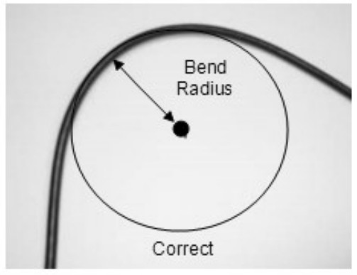
- Mount on a surface that is free from dirt, grime, water and grease to avoid damaging the mounting surface or the vehicle’s paint.
- Mount so that the cable end faces the rear of the vehicle.
- For fixed installations ensure that the satellite antenna is pointing towards the equator, facing south if in theNorthern Hemisphere and facing north if in the Southern Hemisphere, and its line-of-sight to the sky (satellite) is clear of obstructions.
- For a mobile installation, mount the antenna at the highest point on the vehicle or vessel where it has a clear view of the sky (satellite) in all directions.
4.1.4.Review the Cellular Antenna Mounting Guidelines
- Mount outdoors, for example, on top of a heavy machine roof (for example, excavator).
- Mount the cellular antenna at least 1 m (39 in) away from the satellite antenna.
4.2.Mount the Antennas
The transceiver operates with a satellite antenna and/or a cellular antenna.
4.2.1.Mount the Satellite Antenna
If mounting asatelliteantenna, the following tools and materials are required:
- Drill
- M4 hardware
- Outdoor waterproof adhesive sealant (silicone)
To mount the antenna, follow the steps below.
- Find a location for the antenna following the guidelines provided earlier.
- Use the antenna as a template, to mark the location of the mounting holes.
CAUTION: Cable management and connector strain relief must be incorporated in the installation. Ensure the
cable exits straight for at least the first 64 mm (2.5 in.), and then secure it shortly after this point and at regular intervals along its length as part of the installation to prevent cable wear and eliminate strain on the transceiver connector. Damage to the transceiver connector interface or cable may result in hardware failure.
CORRECT √ INCORRECT X
- Drill the holes using a drill.
- Apply waterproof sealing compound, such as RTVsilicone, around the drill holes so water does not leak into the asset.
CAUTION: Do not block the air vent features (two places).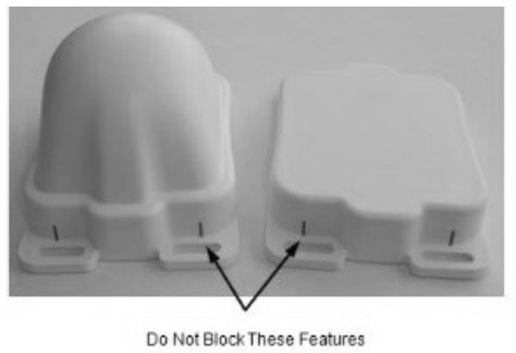
- Secure the antenna in place with self-tapping screws or machine screws and nuts depending on access tthe mounting surface.
4.2.2.Cellular Antenna
If mounting a cellular antenna, the following tools and materials are required:
- Is opropyl alcohol or an equivalent
- Drill
- M4 / #8 hardware
- Outdoor waterproof adhesive sealant (silicone)
- Clean the antenna mounting surface with isopropyl alcohol to remove any dirt or grime. Make sure the surface is dry before installing the antenna.
- Use the cellular antenna, with attached bracket, as a template to mark and drill four (4) holes in the asset.

- Use M4 / #8 hardware to secure the antenna bracket to the asset.
- Apply waterproof sealing compound, such as RTV silicone, around the drill holes so water does not leak into the asset.
4.3.Route the Main Cable
Consider the following guidelines before routing the cable assembly.
CAUTION: Ensure the power cable is not pinched, kinked or worn down by any objects or moving parts such as the door hinges. It is very important to secure the cable at many points along its path.
CAUTION: Prior to working on any cabling, ensure that the transceiver is powered off and unable to start while work is in progress.
- Do not route the cable near the engine if routing through the engine compartment. This location subjects the cable to extreme heat.
- Keep the cable away from hot surfaces such as exhaust pipes because this may damage the cable.
- Do not run the cable over sharp or jagged edges.
- Place the cable in recesses and channels, whenever possible, to prevent potential damage or wear by foot traffic.
Note: Remember to leave enough cable slack near the transceiver for strain relief so as not to introduce any additional force on the connector. ORBCOMM recommends securing the cables during installation.
Sample Cable Placement in a Vehicle Cab 4.3.1.Protect the Cables and Cable Connectors
CAUTION:Cable management and connector strain relief must be incorporated in the installation. ORBCOMM highly recommends securing the cable at regular intervals along its length as part of the installation to prevent cable wear and eliminate strain on the connector. Damage to the connector interface or cable may otherwise result and lead to hardware failure.
To protect the transceiver’s connector interface, follow the guidelines below:
- Apply tape around the cable ends to help in routing the cable.
- Secure the cablesuch that it does not pull on the connector or strain the transceiver connector.
- Tie the cable down so that the weight of a vibrating cable does not stress or strain the connection.
- Tie the cable down using cable ties and tie holders at 30 to 60 cm (12 to24 in.) intervals along the cable route to prevent chafing, wear, or strain.
- Secure the cable tie holder with a self-tapping screw for best holder retention.
4.4.Connect the Cables and Mount the Transceiver
Note: The Solution Provider is responsible for providing mounting instructions if the mounting is to be done using tools or configurations that are different from the ones described in this document.
Note: The Installer is responsible for complying with local electrical codes.
CAUTION: Cable management and connector strain relief must be incorporated in the installation.
ORBCOMM highly recommends securing the cable at regular intervals along its length as part of the installation to prevent cable wear and eliminate strain on the connector. Damage to the connector interface or cable might result and lead to hardware failure.
4.4.1.Connect the Cables
- Connect the satellite antenna to the curry yellow FAKRA connector on the transceiver by pushing until you hear a click.
CAUTION: Use only color-matching antennas.
- Connect the cellular antenna to the violet FAKRA connector on the transceiver by pushing until you hear a click.
CAUTION: Use only color-matching antennas.
- Connect the power and I/O cable to the transceiver by pushing and twisting until it locks in place.

4.4.2. Mount the Transceiver
- Review the mounting guidelines before permanently mounting the transceiver.
- Mount the transceiver using cable ties or washers and screws. You can use cable ties if the transceiver remains flat and is either parallel or perpendicular to the ground, for proper operation of the internal accelerometer. Otherwise, fasten the transceiver to a rigid surface using washers and screws.
Use the holes to mark and drill pilot holes based on the type of screws.
There are multiple flanges or cable tie locations around the transceiver.

4.5.Connect to Power
CAUTION: Apply power only after making ground connection.
CAUTION: Before applying power to the transceiver, make sure that your power supply’s rated voltage follows the recommended values.
CAUTION: The installer is responsible for complying with local electrical codes.
Note: ORBCOMM recommends that,if possible, you wait until the terminal is unblocked (has a full view of the sky) before powering on the transceiver.
- Locate the main power input and the ground (GND) wires. You can connect the transceiver ground to ground in the fuse panel or to chassis ground. To do this, secure the ground wire on the cable assembly to a piece of metal electrically connected to the vehicle chassis using a sheet metal screw.
- Ensure that the main power input and ground wires reach the vehicle fuse panel. If the wires are not long enough, splice similar gauge wires to the main power input and ground wires so
that they reach the fuse panel. Cover any splices with adhesive lined heat shrink. - Correctly mate connectors before applying power.
- Connect the ground wire to the grounding point selected in an earlier step. Check that the polarity is correct, and the voltage source is 9-32 VDC.
- Connect the main power input wire to the unswitched vehicle power source within the fuse panel.
- Loop and secure any excess cabling.
If your application requires extended cable lengths, it is necessary to calculate the cable voltage drop to determine if the transceiver is receiving at least 9 V (with 1.7 A draw). Large cable voltage drops might adversely affect transceiver operation.
4.6. Register and Activate the Terminal
Note: The terminal must complete registration to operate. Once you apply power, the terminal goes into satellite search mode to acquire the IsatData Pro network. This activity may take a few minutes to complete. The terminals must complete registration to operate. Once the terminal synchronizes itself with the network, it sends a registration message to the IsatData Pro network. The terminal will not register until it has a clear line-of-sight to the satellite. The IsatData Pro network records the registration message and forwards the registration message to the user’s application. The IsatData Pro network sends an acknowledgment message over the satellite to the terminal. The terminal is now available to send and receive messages via satellite.
![]() ORBCOMM® PROPRIETARY AND CONFIDENTIALMATERIAL ©Dec 2023, Version 03
ORBCOMM® PROPRIETARY AND CONFIDENTIALMATERIAL ©Dec 2023, Version 03
GJD413-ECert-E
© ORBCOMM®
Documents / Resources
 |
ORBCOMM ST9100 Dual Mode Terminal [pdf] User Guide ST9100, XGS-ST9100, ST9101, ST9100 Dual Mode Terminal, ST9100, Dual Mode Terminal, Mode Terminal, Terminal |