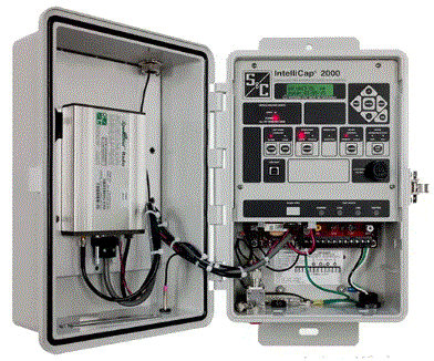
IntelliCap 2000 Automatic Capacitor Control
Product Information
Specifications
- Model: IntelliCap 2000 Automatic Capacitor Control
- Control Type: Microprocessor-based
- Designed for: Pole-mounted and pad-mounted switched capacitor banks
- Control Applications: Stand-alone and SCADA applications
Conditions of Sale
STANDARD
The seller’s standard conditions of sale set forth in Price Sheet 150 apply except as modified under “Warranty Qualifications” on page 3.
SPECIAL TO THIS PRODUCT
INCLUSIONS
- The microprocessor-based IntelliCap 2000 Automatic Capacitor Control is specifically designed for the control of pole-mounted and pad-mounted switched capacitor banks, both in stand-alone and SCADA applications. Automatic control strategies are software selectable.
- The IntelliCap 2000 Automatic Capacitor Control can be set up locally with a computer through a local USB connection or through an optional Wi-Fi connection. Monitoring and troubleshooting are easy to perform using the faceplate tactile-feedback switches and liquid-crystal display, which shows real-time data and key setpoints. A PC using the Windows® 10 or later operating system can be connected via a USB faceplate connector. IntelliLink® Setup Software is used to view real-time data, manage set points, troubleshoot, and download historical data for reports. The faceplate includes a manual override switch and test points for sensor inputs. An operation counter is provided as a software function. The data logging and perpetual calendar are implemented with non-volatile memory.
The IntelliCap 2000 Automatic Capacitor Control provides a full range of automatic functions:
- Voltage, time, temperature, time-biased voltage, and time-biased temperature control strategies
- Optional var and current control strategies
- Optional neutral-current or voltage sensing to detect blown fuses and stuck switches
- Voltage/temperature override
- Automatic calculation of voltage change caused by capacitor bank switching
- Daily limit on the number of automatic switching operations
- Automatic adjustments for daylight savings time and holidays
- SCADA-override strategy, which allows the master station to issue a command and returns the control to its regular programmed strategy after a user-selected period of time
Line voltage, current, kWs, kVAs, kVARs, power factor, temperature, and harmonics can all be accessed in real time. The IntelliCap 2000 Automatic Capacitor Control calculates total harmonic distortion as well as the third through 15th harmonics every 15 minutes.
- The IntelliCap 2000 Automatic Capacitor Control provides true RMS voltage and current readings. Over the operating temperature range of -40° F (-40° C) to 158° F (70° C), temperature readings are accurate to ±2° F
(±1° C); current readings are accurate to ±0.15% full scale, with a resolution of 1 ampere RMS; and voltage readings are accurate to ±0.15% full scale, with a resolution of 0.1 Vac. Phase-angle readings are accurate to ±1° at 10% of full-scale current, with a resolution of 1/8°. - The IntelliCap 2000 Automatic Capacitor Control includes extensive data-logging capabilities.
The following parameters are logged and can be downloaded as tables or graphs:
- Temperature, voltage, current, power factor, kVAR, kW, and neutral current/voltage (if applicable) (Logging intervals can be adjusted from 1 minute to 120 minutes, in 1-minute intervals [15 minutes is default], for two days to 120 days of voltage and temperature data.)
- Up to 10,000 Historic Log entries—includes switching events and the date and time of power cycles
- Daily minimum and maximum voltages, temperatures, current, kWs, kVARs, power factor, and neutral current/voltage (if applicable), and number of switching cycles in the last month and since installation
- The IntelliCap 2000 Automatic Capacitor Control supports both one-way and two-way communication. Distributed Network Protocol (DNP) 3.0 is the standard protocol. A variety of communication devices may be furnished and installed by S&C in the IntelliCap 2000 control enclosure. A variety of customer-furnished communication devices may be accommodated as well. Refer to Table 3 on pages 7 through 9.
EXCLUSIONS
- The IntelliCap 2000 Automatic Capacitor Control does not include a neutral sensing input, communication device, antenna, antenna connections, sensors, or cables. S&C may be able to furnish and install in the IntelliCap 2000 control enclosure, or make provision for, a customer-specified communication device not listed in Table 3 on pages 7 through 9. S&C must to evaluate the physical and electrical requirements of the communication device and its performance characteristics, and conduct qualification testing to verify its suitability for the desired application.
- Refer to the nearest S&C Sales Office for scheduling information. S&C cannot furnish or install any communication device for which the supplier requires S&C to offer Tier 1 (i.e., “help desk”) support.
SPECIFICATION DEVIATIONS
Refer to the Options Table 3 on pages 7 through 9.
How To Order
Complete the following steps to build an IntelliCap 2000 Automatic Capacitor Control catalog number. Included with the steps are fill-in boxes to help keep track of the various components of the final catalog number.
Note: Pay strict attention to the various table footnotes, which identify constraints and considerations regarding the selection of the various options.
- STEP 1. Choose the capacitor control catalog number from Table 1 on page 5.
- STEP 2. Choose the mounting type suffix from Table 2 on page 6.
 Note: If the mounting type is not selected, an M-option from Step 2 must be specified.
 - STEP 3. (Optional) Choose the suffixes for any desired options from Table 3 on pages 7 through 9.

- STEP 4. (Optional) Choose the catalog numbers for any accessories from Table 5 on page 11.

- STEP 5. (Optional) Choose the catalog number for the desired power cables from Table 6 on page 11.

- STEP 6. (Optional) Choose the appropriate catalog number for sensor cables from Table 7 on page 11 and Table 8 and Table 9 on page 12.

- STEP 7. (Optional) Choose the catalog number for the applicable meter box from Table 10 on page 12.

Example: The catalog number for an IntelliCap 2000 control with a USB connector for local communication and a pad lockable Lexan® NEMA 3R enclosure; control strategies that include time, temperature, and voltage; single-phase voltage sensing provided by a customer-furnished voltage transformer; a pole-mounting bracket; and a GPS module with a door-mounted N-Type 900-MHz 5-dB GPS antenna is 240120-JB1A4T2S1.![]()
Table 1. IntelliCap 2000 Automatic Capacitor Controls
| Device | Control- Source Voltage | Output Relay Contacts | Control Strategies | Catalog Number | Page Reference for Dimensional Information | Net Wt . Lbs . (Kg .) |
| IntelliCap 2000 control with USB connector for local communication and padlockable Lexan NEMA 3R enclosure . Does not include neutral sensing input communication device, antenna, or antenna connections .Mounting type must be specified from Table 4 on page 10 | 100 to135 Vac,50 or60 Hz | 1 open,1 closed; pulsed or latched; rated 20 A at 250 Vac,1 HP at 120/250 Vac single phase, 3 digital inputs | Standard: time, temperature, and voltage, with single-phase voltage sensing provided by a customer-furnished voltage transformer | 240120 | 17 | 8¼ (3 .74) |
| Standard plus var and current with single- phase current sensing provided by a customer-furnished or S&C-furnished CS or CSV Line Post Sensor | 240160●■ | 18 | 8¼ (3 .74) | |||
| Standard plus var and current with single-phase current sensing provided by a customer-furnished 0- to 1-A or 0- to 5-A current transformer | 240164▲ | 19 | 8¼ (3 .74) |
- ●Refer to Specification Bulletin 1061-31 for ordering information on CS and CSV Line Post Sensors. Cables are required. Refer to Table 7 on page 11 and Table 8 and Table 9 on page 12 for ordering information.
- ■Customer to provide shorting block.
- ▲Customer-furnished sensors must be high-impedance, low output-energy sensors, to avoid damaging the sensor input and voiding the warranty. A burdened current transformer of any kind cannot
be used.
Ordering Tables
Table 2. Mounting Type—Must Be Specified
|
Item |
Suffix to Be Added to IntelliCap 2000 Catalog Number |
| Four-jaw electric meter base①② | -J40 |
| Four-jaw electric meter base①② | -J41 |
| Four-jaw electric meter base①② | -J42 |
| Six-jaw electric meter base①③④ | -J60 |
| Six-jaw electric meter base①③ | -J61 |
| Six-jaw electric meter base①③ | -J62 |
| Six-jaw electric meter base①③ | -J63 |
| Six-jaw electric meter base①② | -J64 |
| Six-jaw electric meter base①② | -J65 |
| Pole-mounting bracket⑤ | -JB1 |
| Wall-mounting bracket①⑤ | -JB2 |
| Demonstration stand | -JB9 |
| Wall-mounting bracket with 3-foot (91-cm) cable, standard wiring② | -J67 |
| Six-jaw electric meter base① | -J68 |
| Mounting: Wall-mounting bracket with 3-foot (91-cm) cable . Standard wiring with var for current transformer⑥ | -J69 |
| Mounting: Wall-mounting bracket with 3-foot (91-cm) cable . Standard wiring with var plus neutral, for current transformer⑥ | -J70 |
- See page 13 for electric meter base wiring configuration.
- Not available on IntelliCap 2000 control catalog numbers 240160 and 240164.
- Not available on IntelliCap 2000 control catalog number 240120.
- Only available on IntelliCap 2000 control catalog number 240160 with neutral input sensing (options “-N1,” “-N2,” “-N3,” or “-N4”).
- See page 14 for connector configurations.
- Only available on IntelliCap 2000 control catalog number 240164.
Table 3. Options
| Item | Suffix to Be Added to IntelliCap 2000 Catalog Number | |
| Wi-Fi module with antenna, for wireless setup (Not available outside the United States and Canada . Contact S&C for options in other countries) | -A3 | |
| GPS module (requires GPS antenna . See Table 5 on page 11 . Antenna is included with Wi-Fi module with antenna, suffix “-A3” | -A4 | |
| Wi-Fi/GPS module with antenna, for wireless setup (Not available outside the United States and Canada . Contact S&C for options in other countries) | -A5 | |
| Terminal block cover | -C | |
| Door switch, provides “Cabinet Door Open” indication when connected to User Status Input | -D | |
| Neutral alarm LED indicator | -E | |
| Control for 50-Hz system frequency | -H | |
| Voltage Input, 0- to 10-V from S&C CSV Line Post Current/Voltage Sensor | -K1 | |
| Reversed colors for OPEN/CLOSE indicators (green = closed, red = open) | -L1 | |
| Foreign language labels, front panel, and screens① | Spanish | -L51 |
| Portuguese | -L52● | |
| French | -L53 | |
| Chinese | -L54 | |
| Arabic | -L55 | |
| Connectors (multiple types may be specified; standard is terminal strip; option is for bracket mounting, pole, or wall) | ||
| Neutral sensor cable entry, opening blocked with shipping plug | -M0 | |
| Five-pin mil spec for bracket-mounted control | -M1■ | |
| Seven-pin mil spec for bracket-mounted control | -M3■ | |
| Three-pin mil spec for phase current input | -M5■▲ | |
| Three-pin mil spec for neutral current/voltage input | -M7■ | |
| Five-pin mil spec for user definable digital inputs | -M11■ | |
| Neutral Input Sensing | ||
| Current input, 0-10 V② | -N1◆ | |
| Potential transformer voltage sensor input, 0-144 Vac | -N2 | |
| S&C Voltage Sensor Input, 0-144 Vac | -N3 | |
| Lindsey Voltage Sensor Input, 0-5 Vac | -N4 | |
| Fisher-Pierce AT 929 Sensor Input | -N5 | |
| Communication Protocol | ||
| DNP 3 .0 | -P0 | |
- Labels will add four weeks to lead time. Spanish front panels are available. Contact the nearest S&C Sales Office for French, Chinese, and Arabic front panel availability, and screen availability.
- Neutral current sensors should only be applied on double-bushing capacitors. Single-bushing capacitors have a ground connection internally connected to the case and are grounded through the mounting rack; there is no common point where the three phase currents can be sensed.
- ● Portuguese labels and front panels are available at standard lead times.
- ■ Multiple connectors may be specified. See Table 4 on page 10.
- ▲ May also be used with a four-jaw socket mount control.
- ◆ Refer to Specification Bulletin 1062-31 for ordering information on neutral current sensors.
| Item | Suffix to Be Added to IntelliCap 2000 Catalog Number |
| Communication Device and Mounting (furnished by S&C, requires suffix “-R98”)① | |
| MDS TransNET 900 Transceiver | -R18 |
| RFI 594 UHF Radio Modem | -R33 |
| Multi-Mode Dymec 5843HRT Fiber-Optic Modem | -R45 |
| Telemetric DNP-RTMII-FLX for FlexNet system | -R148 |
| MDS SD9 Remote Radio | ● |
| SpeedNet™ Cell Edge Gateway 4G LTE cellular modem with removable SIM card for USA and Canada② | -R352 |
●Specify the appropriate catalog number suffix based on the frequency band range and application for the radio from the following table. For example, for a 928- to 960-MHz MDS SD9 Radio for Ethernet and serial application, specify catalog number suffix “-R216CL.” NOTE: The power supply is capable of providing 12-W average continuous power to the radio. Peak transmit is limited to 20 W for a maximum of 250 ms.
- More radios will be added to the list in the future. For other radios not yet in the table, contact S&C.
- See Specification Bulletin 1076-31 for SpeedNet Cell Edge Gateway antenna options.
| Frequency Band Range, MHz | Application | Suffix to Be Added to Catalog Number |
| 820 to 870 | Serial | -R216AK |
| 928 to 960 | -R216CK | |
| 928 to 960, 50-kHz channel | -R216DK | |
| 880 to 915 | -R216EK | |
| 880 to 915, 50-kHz channel | -R216FK | |
| 850 to 860 / 926 to 936, transmit low | -R216GK | |
| 850 to 860 / 926 to 936,transmit high | -R216HK | |
| 820 to 870 | Ethernet and Serial | -R216AL |
| 928 to 960 | -R216CL | |
| 928 to 960, 50-kHz channel | -R216DL | |
| 880 to 915 | -R216EL | |
| 880 to 915, 50-kHz channel | -R216FL | |
| 850 to 860 / 926 to 936, transmit low | -R216GL | |
| 850 to 860 / 926 to 936, transmit high | -R216HL | |
| 820 to 870 | 9710 Emulation | -R216AM |
| 928 to 960 | -R216CM | |
| 928 to 960, 50-kHz channel | -R216DM | |
| 880 to 915 | -R216EM | |
| 880 to 915, 50-kHz channel | -R216FM | |
| 850 to 860 / 926 to 936, transmit low | -R216GM | |
| 850 to 860 / 926 to 936, transmit high | -R216HM |
| Item | Suffix to Be Added to IntelliCap 2000 Catalog Number |
| Communication Device Ready for (communication device furnished by customer) | |
| MDS 9810 Radio | -R02 |
| MDS TransNet 900 Radio | -R07 |
| Silver Spring Networks eBridge Radio | -R125 |
| Telemetric DNP-RTMII-FLX for FlexNet system | -R147 |
| MDS Mercury 3650 HGR3 Remote Radio | -R151 |
| MDS SD9 Remote Radio | -R188 |
| Cradlepoint COR IBR600 Series integrated broadband routers | -R266 |
| Ready for Tantalus DA Bridge Modem | -R273 |
| Sierra Wireless RV50 LTE cellular modem | -R316 |
| GE MDS Orbit ECR wireless router with single WAN radio | -R328 |
| Cisco IR807 Integrated Services Router with 4G LTE cellular modem | -R330 |
| Landis+Gyr Series 5 Network Integrated WanGate Radio (IWR) | -R399 |
| Installation of Communication Device | |
| Furnished by S&C | -R98 |
| Furnished by customer | -R99 |
| Antenna Connections | |
| N-Type connector, door top mounted (for mounting whip antenna) | -S1 |
| N-Type connector, bottom mounted (for remote antenna installation) | -S2 |
| PolyPhaser® Surge Suppressor, N-type connector, bottom mounted (for remote antenna installation) | -S3 |
| NMO-type mounting for Antenex Phantom Antenna, door top | -S4 |
| Dual-band cellular antenna connection | -S5 |
| PolyPhaser® Surge Suppressor, N-type connector, 800-2300 MHz, for dual band cellular antenna | -S6 |
| Antenna | |
| 900-MHz 5-dB gain antenna, door mounted | -T2 |
| Antenex Spread-Spectrum Antenna | -T3 |
| Antenex Phantom Antenna, model TRAB821/18503P, dual band (821-896 and 1850-1990 MHz), 3 dB-MEG | -T4 |
| Dual Band LoPro® Cellular Antenna (824-896 and 1850-1990 MHz), 3 dBi | -T7 |
| Permanent Phantom Antenna 3G-4G multi-band (698-960, 1700-2700 MHz) N-type female, black | -T18 |
Table 4. Connector Combinations
| Valid Combinations Numbers in () = Connector Positions | Mounting Restrictions | Catalog Restrictions |
| M1 (5) | JB1 and JB2 only | None |
| M3 (7) | JB1 and JB2 only | None |
| M5 (3) | Not allowed with J60, J61, J62, J63, J64, J69, and J70 | Not allowed with 240120 |
| M7 (3) | Not allowed with J60, J68, and J70 | None |
| M11 (5) | None | None |
| M1 (5), M5 (3) | JB1 and JB2 only | Not allowed with 240120 |
| M1 (5), M7 (3) | JB1 and JB2 only | None |
| M1 (5), M11 (5) | JB1 and JB2 only | None |
| M1 (5), M5 (3), M7 (3) | JB1 and JB2 only | Not allowed with 240120 |
| M5 (3), M7 (3) | Not allowed with J60, J61, J62, J63, J64, J68, J69, and J70 | Not allowed with 240120 |
| M3 (7), M11 (5) | JB1 and JB2 only | None |
| M5 (3), M11 (5) | Not allowed with J60, J61, J62, J63, J64, J69, and J70 | Not allowed with 240120 |
| M7 (3), M11 (5) | Not allowed with J60, J68, and J70 | None |
| M5 (3), M7 (3), M11 (5) | Not allowed with J60, J61, J62, J63, J64, J68, J69, and J70 | Not allowed with 240120 |
| K1 (3) | None | None |
| K1 (3), M1 (5) | JB1 and JB2 only | None |
| K1 (3), M3 (7) | JB1 and JB2 only | None |
| K1 (3), M5 (3) | Not allowed with J60, J61, J62, J63, J64, J69, and J70 | Not allowed with 240120 |
| K1 (3), M7 (3) | Not allowed with J60, J68, and J70 | None |
| K1, M11 (5) | None | None |
| K1, M1 (5), M5 (3) | JB1 and JB2 only | Not allowed with 240120 |
| K1, M1 (5), M7 (3) | JB1 and JB2 only | None |
| K1, M1 (5), M11 (5) | JB1 and JB2 only | None |
| K1, M5 (3), M7 (3) | Not allowed with J60, J61, J62, J63, J64, J68, J69, and J70 | Not allowed with 240120 |
| K1, M3 (7), M11 (5) | JB1 and JB2 only | None |
| K1, M5 (3), M11 (5) | Not allowed with J60, J61, J62, J63, J64, J69, and J70 | Not allowed with 240120 |
| K1, M7 (3), M11 (5) | Not allowed with J60, J68, and J70 | None |
Table 5. Accessories
| Description | Model | Catalog Number | |
|
Remote antenna kit, includes omnidirectional antenna, mounting bracket |
With 30-foot (9 .1-m) coaxial cable with connectors on both ends |
MA-30-PM |
903-002132-02 |
| With 50-foot (15 .2-m) coaxial cable with connectors on both ends |
MA-50-PM |
903-002132-03 |
|
| WanGate Pole-Mount Bracket, includes 40-foot (12 .2-m) communications cable, order with catalog number suffix “-R06” | — | 903-002174-01 | |
Table 6. S&C Power Cables—Control to Junction Box
| For Use with IntelliCap 2000 Catalog Number | Length, Feet (Centimeters) | End One Connector | End Two Connector | Catalog Number |
| 240120 | 30 (914) | 5-pin | 5-pin | 007-001236-02 |
| 35 (1067) | 5-pin | None | 007-000262-04 | |
| 35 (1067) | 5-pin | 5-pin | 007-001236-01 | |
| 40 (1219) | 5-pin | None | 007-000262-01 | |
| 40 (1219) | 5-pin | 5-pin | 007-001236-03 | |
| 50 (1524) | 5-pin | None | 007-000262-03 |
Table 7. S&C Sensor Cables—Control to Junction Box
| For Use with IntelliCap 2000 Catalog Numbers | Length, Feet (Centimeters) | End One Connector | End Two Connector | Catalog Number |
| 240120 and 24016 | 35 (1067) | 7-pin | None | 007-001138-01 |
| 35 (1067) | 7-pin | 7-pin | 007-001139-01 | |
| 40 (1219) | 7-pin | None | 007-001138-02 |
Table 8. S&C Sensor Cables—Junction Box to Current Sensor
| For Use with IntelliCap 2000 Catalog Number | Length, Feet (Centimeters) | End One Connector | End Two Connector | Catalog Number |
|
240160 |
20 (610) | None | None | 007-000973-04 |
| 20 (610) | 2-pin | 007-000767-03 | ||
| 30 (914) | 2-pin | 007-000767-04 | ||
| 35 (1067) | None | 007-000973-03 | ||
| 35 (1067) | 2-pin | 007-000767-05 | ||
| 40 (1219) | None | 007-000973-01 | ||
| 40 (1219) | 2-pin | 007-000767-01 | ||
| 50 (1524) | None | 007-000973-02 | ||
| 50 (1524) | 2-pin | 007-000767-02 |
Table 9. S&C Sensor Cables—Control to Current Sensor
| For Use with IntelliCap 2000 Catalog Number | Length, Feet (Centimeters) | End One Connector | End Two Connector | Catalog Number |
| 240160 | 20 (610) | 3-pin | 2-pin | 007-000261-04 |
| 35 (1067) | 007-000261-05 | |||
| 40 (1219) | 007-000261-01 | |||
| 50 (1524) | 007-000261-03 | |||
| 60 (1829) | 007-000261-02 | |||
| 65 (1981) | 007-000261-07 |
Table 10. Meter Base—Includes Mounting Bracket and Meter Ring
| For Use with IntelliCap 2000 Catalog Number | Type | Catalog Number |
| 240120 | 4-jaw | 904-000005-00 |
| 240120, 240160, 240164 | 6-jaw | 904-000005-01 |
Schematics and Dimensional Drawings
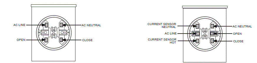
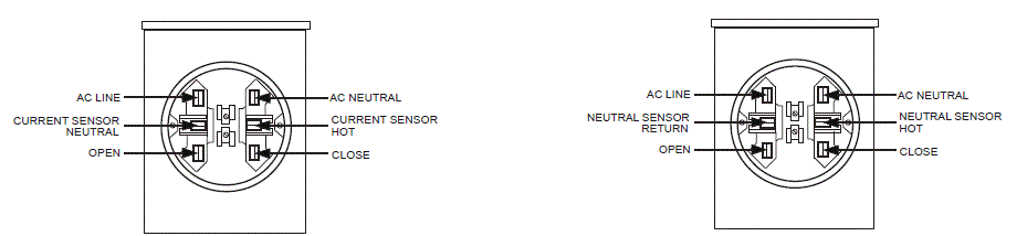
Electric Meter Base Wiring Configurations
- Four-Jaw Electric Meter Base, Catalog Number Suffi x“-J40” (Catalog number suffi x “-J41” reverses ac line and ac neutral). (Catalog number suffi x “-J42” reverses open and close)
- Six-Jaw Electric Meter Base, Catalog Number Suffi x “-J63”
- Six-Jaw Electric Meter Base, Catalog Number Suffi x “-J60”
- Six-Jaw Electric Meter Base, Catalog Number Suffi x “-J64”
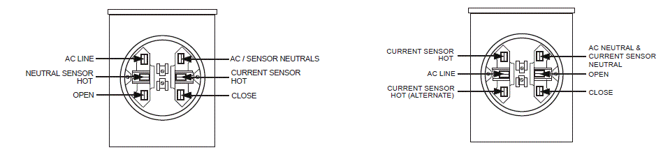
- Six-Jaw Electric Meter Base, Catalog Number Suffi x “-J61”
- Six-Jaw Electric Meter Base, Catalog Number Suffi x “-J65”
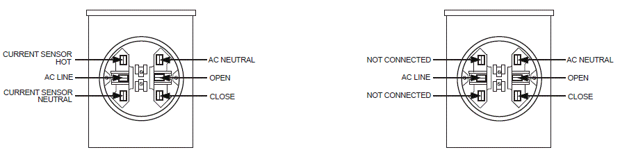
- Six-Jaw Electric Meter Base, Catalog Number Suffi x“-J62”
- Six-Jaw Electric Meter Base, Catalog Number Suffi x “-J68”
Connector Configurations—For Wall or Pole-Mounting Bracket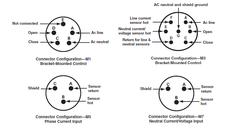
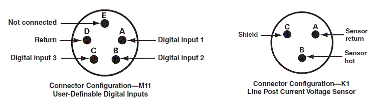
Terminal Strip Configuration—For Wall or Pole-Mounting Bracket
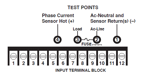
INPUT TERMINALS
- Ac neutral (connected to terminal 12)
- Digital Input 3—user-defined
- Digital Input 2—operator close
- Digital input I—operator open
- CT or phase current sensor hot (+)
- CT return
- Neutral sensor hot (+)
- Open
- Close
- Acellne—motor operator power
- Ac.llne—control power and sensing
- Ac-neutral and sensor return(s)(—)
Current transformers (CTs) can only be used with catalog number 240164. Customer-furnished current sensors used with catalog number 240160 must be high-impedance low output-energy sensors to avoid damaging the sensor input and voiding the warranty. A burdened current transformer of any kind cannot be used.
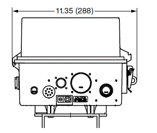
Typical Installation of IntelliCap 2000 Automatic Capacitor Control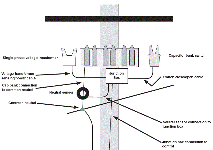

NOTE: Neutral sensor is optional and includes the cable.
Typical Installation of IntelliCap 2000 Automatic Capacitor Control Catalog Numbers 240160 and 240164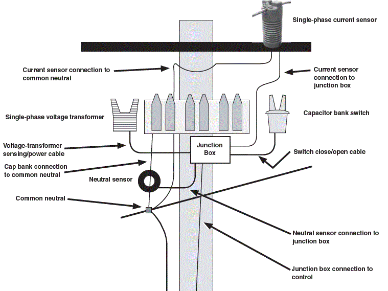

NOTE: Neutral sensor is optional and includes the cable.
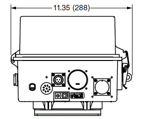
IntelliCap 2000 Automatic Capacitor Control Meter-Base Mounted
Dimensions in inches (millimeters)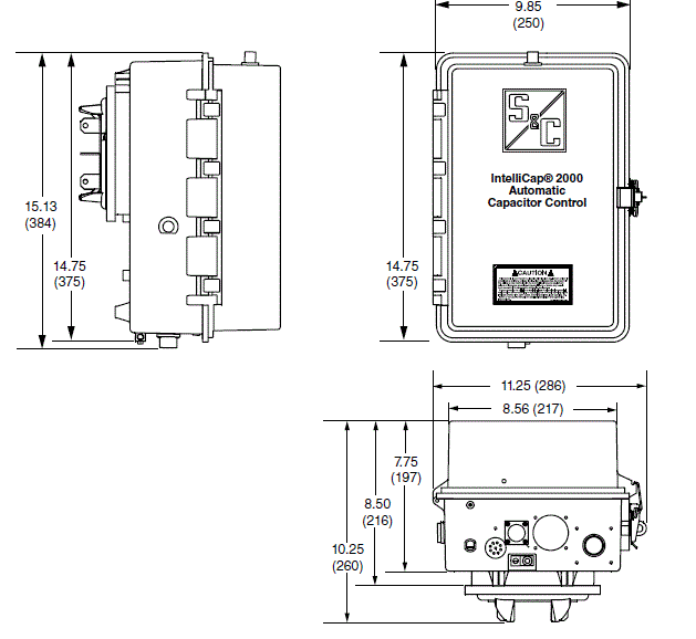
IntelliCap 2000 Automatic Capacitor Control Pole-Mounted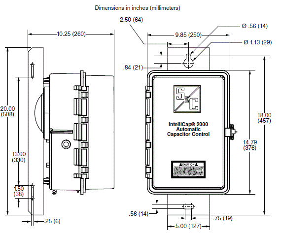
IntelliCap 2000 Automatic Capacitor Control Wall-Mounted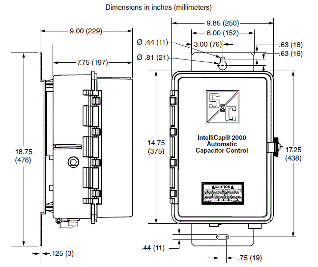
WARRANTY QUALIFICATIONS
- Warranty of IntelliCap 2000 Automatic Capacitor Controls is contingent upon the installation, configuration, and use of the control or software in accordance with S&C’s applicable instruction sheets. To avoid damaging the sensor input and voiding the warranty, customer-furnished sensors must be high-impedance, low output-energy sensors. A burdened current transformer of any kind cannot be used.
- This warranty does not apply to major components not of S&C manufacture, such as batteries, communication devices, and remote terminal units. However, S&C will assign to the immediate purchaser or end user all manufacturers’ warranties that apply to such major components.
END USER LICENSE AGREEMENT
The end user is granted a nontransferable, non-sub-licensable, nonexclusive license to use the IntelliLink® Setup Software and/or other software furnished with IntelliCap 2000 Automatic Capacitor Controls only upon acceptance of all the terms and conditions of the seller’s end user license agreement set forth in Price Sheet 155.
FAQ
Can the IntelliCap 2000 support remote monitoring?
Yes, the IntelliCap 2000 supports both one-way and two-way communication for remote monitoring capabilities.
What is the default logging interval for data storage?
The default logging interval is set at 15 minutes, but it can be adjusted from 1 minute to 120 minutes based on user preferences.
Documents / Resources
 |
IntelliCap 2000 Automatic Capacitor Control [pdf] Instruction Manual 2000 Automatic Capacitor Control, 2000, Automatic Capacitor Control, Capacitor Control, Control |