![]() ISP1807
ISP1807
Data Sheet
Owner’s Manual
ISP1807 Built In Antenna Low Energy Module
Built-in Antenna Low Energy Module BT 5 Long Range, Zigbee, Thread, Matter, ANT+  Key Features
- 2.4GHz Ultra Low Power RF Transceiver
- Full Bluetooth 5 – long range stack ANT/ANT+ stack 2.4 GHz proprietary stack
- BT Mesh, Zigbee, Thread, Matter stacks available
- NFC-A Tag for OOB pairing
- Fully integrated RF matching and Antenna
- Integrated 32 MHz& 32kHZ Clock
- DC/DC converter with loading circuit
- Based on Nordic Semiconductor nRF52
- 32-bit ARM Cortex M4F CPU
- ARM CryptoCell 310
- 1 MB Flash / 256 kB SRAM
- Configurable 46 GPIOs including 8 ADC
- Many interfaces USB, SPI, UART, PDM, I2C
- Power supply 1.7 to 3.6V, USB supply 5V
- Very small size 8.0 x 8.0 x 1.0 mm
- Temperature -40 to +85 °C
- Pin to Pin compatible with ISP1507
Applications
- Advanced Wearables: watches, fitness devices, wireless payment wearables, connected health, augmented reality applications …
- Smart Home sensors and controllers
- Industrial IoT sensors and controllers
- Advanced remote controls
- Remote &Gaming controllers
- Beacons

- Bluetooth SIG certified
- CE certified
- FCC, IC certified
- TELEC, KCC certified
- RoHS and Reach compliant
- Conflict Mineral Declaration
Revision History
| Revision | Date | Ref | Change Description |
| R0 | 23/11/2017 | cr pg | Preliminary release |
| R1 | 12/12/2017 | cr pg | Engineering samples release |
| R2 | 20/04/2018 | cr pg | Section 5.2 – FW tool correction and update Section 6.5 – Extension name change |
| R3 | 22/08/2018 | cr pg | Section 3 – Typo error correction |
| R4 | 12/12/2018 | cr pg | Section 2.9 – Schematic updated |
| R5 | 18/02/2019 | cr pg | Definitive release |
| R6 | 14/03/2019 | cr pg | Correction VCC / VCCH No High-Power Mode availability |
| R7 | 06/06/2019 | mm pg | Change to MSL3 |
| R8 | 08/11/2019 | mm pg | Section 4.1 – Mechanical dimension precision Section 8 – Certification list update |
| R9 | 17/04/2020 | cb pg | Section 4.2 – Assembly guideline precisions Section 8 – Certification list update |
| R10 | 03/05/2021 | vn pg | Section 8 – Certification list update |
| R11 | 29/04/2022 | pd pg | Document layout update |
| R12 | 09/11/2022 | ys pg | Section 2.2 – Absolute Maximum Ratings |
| R13 | 30/11/2022 | er pg | Certifications update & Matter Compliance |
| R14 | 12/04/2023 | mm pg | Packaging information update |
| R15 | 24/08/2023 | er pg | Typo corrections |
| R16 | 30/08/2023 | er pg | Certifications update |
| R17 | 14/03/2024 | pg pg | Certifications update |
| R18 | 14/03/2024 | er pg | ANT+ specifications added in 2.6 |
Block Diagram
This module is based on nRF52840 Nordic Semiconductor 2.4GHz wireless System on Chip (SoC) integrating a 2.4 GHz transceiver, an ARM ®Cortex® -M4 32-bit processor with 64 MHz FPU, a 1 MB flash memory, a 256 kB RAM and analog and digital peripherals.
It can support BLE, ANT/ANT+ and a range of proprietary 2.4 GHz protocols, such as Gazell from Nordic Semiconductor.
Fully qualified BLE stacks for nRF52840 are implemented in the S140 SoftDevices which can be freely downloaded. ISP1807 can then be used in Bluetooth Central, Peripheral, Observer or Broadcaster role with up to 20 connections and for both ends of other proprietary protocols. nRF52840 platform also provides extensive software support for ANT, ZIGBEE and THREAD applications.
Ultra-low power consumption and advanced power management enables battery lifetimes up to several years on a coin cell battery. Even though its very small size 8 x 8 x 1.0 mm, the module integrates decoupling capacitors, 32 MHz and 32.768 kHz crystals, load capacitors, DC-DC converter, RF matching circuit and antenna in addition to the wireless SoC.
Only the addition of a suitable DC power source is necessary for BLE / ANT / ZIGBEE / THREAD connectivity. Sensor applications require the further addition of appropriate sensors. The antenna was designed to be optimized with several standard ground plane sizes. The NFC tag antenna can be connected externally.
Specifications
2.1. Important Notice
The electrical specifications of the module are directly related to the Nordic Semiconductor specifications for the nRF52840 chipset. Bellow information is only a summary of the main parameters. For more detailed information, especially about current consumption, please refer to the up-to-date specification of the chipset available on Nordic Semi website.
2.2. Absolute Maximum Ratings
| Parameter | Min | Typ | Max | Unit |
| Main Supply Voltage respect to ground – VCC_nRF | -0.3 | 3.9 | V | |
| USB Supply Voltage respect to ground – VBUS | -0.3 | 5.8 | V | |
| IO Pin Voltage | -0.3 | 3.9 | V | |
| RF Input Level | 10 | dBm | ||
| NFC Antenna pin current | 80 | mA | ||
| Module Total Capacity | 7.6 | µF | ||
| Module Total Inductance | 13 | µH | ||
| Storage Temperature | -40 | +125 | °C | |
| Moisture Sensitivity Level | 3 | – | ||
| ESD Human Body Model | 2000 | V | ||
| ESD Charged Device Model | 500 | V | ||
| Flash Endurance | 10000 | cycles |
![]() ATTENTION
ATTENTION
CONSERVE PRECAUTIONFOR HANDLING ELECTROSTATIC SENSITIVE DEVICES Human Body Model Class 3A
2.3. Operating Conditions
| Parameter | Min | Typ | Max | Unit |
| VCC_nRF Supply Voltage, independent of DCDC enable | 1.7 | 3.0 | 3.6 | V |
| VBUS Supply Voltage | 4.35 | 5.0 | 5.5 | V |
| Extended Industrial Operating Temperature Range | -40 | +25 | +85 | °C |
2.4. Power Consumption
| Parameter | Min | Typ | Max | Unit |
| Peak Current, Transmitter +8 dBm, VCC 3V + DCDC | 16.4 | mA | ||
| Peak Current, Transmitter 0 dBm, VCC 3V + DCDC | 6.4 | mA | ||
| Peak Current, Receiver 1 Mbps, VCC 3V + DCDC | 6.26 | mA | ||
| System OFF, no RAM retention | 0.4 | µA | ||
| System ON, no RAM retention, wake on RTC | 1.5 | µA | ||
| Additional RAM retention current per 4 KB block | 30 | nA |
2.5. Clock Sources
| Parameter | Min | Typ | Max | Unit |
| Internal High Frequency Clock for RF Stability: 32 MHz Crystal Frequency Tolerance (1) | +/- 40 | ppm | ||
| Internal Low Frequency Clock for BLE Synchronization: 32.768 kHz Crystal Frequency Tolerance (1) | +/- 40 | ppm | ||
| Internal Low Frequency Clock for BLE Synchronization: RC Oscillator (2) | +/- 250 | ppm | ||
| RF Frequency Tolerance for BLE Operation | +/- 40 | ppm |
(1) including initial tolerance, drift, aging, and frequency pulling
(2) Frequency tolerance after calibration
2.6. Radio Specification
| Parameter | Min | Typ | Max | Unit |
| BLE Frequency Range | 2402 | 2480 | MHz | |
| ANT+ Frequency | 2457 | MHz | ||
| Maximum Output Power (BLE) | +8 | +8.5 | dBm | |
| Maximum Output Power (ANT+) | 0 | +1 | dBm | |
| Rx Sensitivity Level, BLE1 Mbps | -95 | dBm | ||
| Rx Sensitivity Level, BLE Long Range 125 kbps | -103 | dBm | ||
| Antenna Gain | 0.6 | dBi | ||
| EIRP | -19.4 | 8.6 | dBm | |
| BLE Data Rate | 125 | 2000 | Kbps | |
| ANT+ Modulation | 1 | Mbps |
2.7. Range Measurement
Range measurement between ISP1807-LR test board (configured as Central) and ISP1807-LR test board (configured as Peripheral).
| Parameter | Min | Typ | Max | Unit |
| Range Open field @1m height (0 dBm, 1 Mbps) | 150 | m | ||
| Range Open field @1m height (0 dBm, 125 Kbps) | 175 | m | ||
| Range Open field @1m height (8 dBm, 1 Mbps) | 230 | m | ||
| Range Open field @1m height (8 dBm, 125 Kbps) | 450 | m |
2.8. Antenna Performance
Typical Antenna Return Loss
Module mounted on a
USB dongle ground plane
Radiation Pattern in 3 planes
Module mounted on a USB dongle ground plane
Gain measurement in dBi in the BLE band from 2.4 to 2.5 GHz.
Ground Plane Effect Simulation
2.9. Electrical Schematic
Electrical schematic showing
ISP1807 module connections
Pin Description
The module uses an LGA format with a double row of pads on a 0.65 mm pitch. The pad layout follows the QFN Jedec standard for 2 row LGA parts. The NC pads are to be connected to isolated metal pads on the application PCB for mechanical stability and reliability (drop test).
| Pin | Name | Pin function | Description |
| 1 | VSS | Ground | Should be connected to ground plane on application PCB |
| 2 | P0_09 NFC1 | Digital I/O NFC Input | General purpose I/O pin NFC antenna connection |
| 3 | P0_12 TRACEDATA1 | Digital I/O | General purpose I/O pin Trace port output |
| 4 | P0_10 NFC2 | Digital I/O NFC Input | General purpose I/O pin NFC antenna connection |
| 5 | P0_14 | Digital I/O | General purpose I/O pin |
| 6 | P0_26 | Digital I/O | General purpose I/O pin |
| 7 | VSS | Ground | Should be connected to ground plane on application PCB |
| 8 | D+ | Digital I/O | USB D+ |
| 9 | P0_16 | Digital I/O | General purpose I/O pin |
| 10 | D- | Digital I/O | USB D- |
| 11 | P0_21 | Digital I/O | General purpose I/O pin |
| 12 | VBUS | Power | 5V input for USB 3.3V regulator |
| 13 | P0_18 RESET | Digital I/O | General purpose I/O pin Configurable as system RESET pin |
| 14 | VSS | Ground | Should be connected to ground plane on application PCB |
| 15 | P0_20 | Digital I/O | General purpose I/O pin |
| 16 | VSS | Ground | Should be connected to ground plane on application PCB |
| 17 | P0_22 | Digital I/O | General purpose I/O pin |
| 18 | VSS | Ground | Should be connected to ground plane on application PCB |
| 19 | P0_24 | Digital I/O | General purpose I/O pin |
| 20 | OUT_ANT | Antenna I/O | This pin is connected to the internal antenna It should be connected to Pin 22 OUT_MOD for normal operation |
| 21 | VSS | Ground | Should be connected to ground plane on application PCB |
| 22 | OUT_MOD | Antenna I/O | This pin is the RF I/O pin of the BLE module It should be connected to Pin 20 OUT_ANT for normal operation |
| 23 | VSS | Ground | Should be connected to ground plane on application PCB |
| 24 | VSS | Ground | Should be connected to ground plane on application PCB |
| 25 | VSS | Ground | Should be connected to ground plane on application PCB |
| 26 | VCC_nRF | Power | Power supply (1.7 – 3.6V) |
| 27 | P0_17 | Digital I/O | General purpose I/O pin |
| 28 | SWDIO | Digital I/O | Serial Wire Debug I/O for debug and programming |
| 29 | P0_13 | Digital I/O | General purpose I/O pin |
| 30 | SWDCLK | Digital Input | Serial Wire Debug clock input for debug and programming |
| 31 | VSS | Ground | Should be connected to ground plane on application PCB |
| 32 | P0_08 | Digital I/O | General purpose I/O pin |
| 33 | P0_07 TRACECLK | Digital I/O | General purpose I/O pin Trace port clock output |
| 34 | P0_06 | Digital I/O | General purpose I/O pin |
| 35 | P0_04 AIN2 | Digital I/O Analog Input | General purpose I/O pin SAADC/COMP/LPCOMP input |
| 36 | P0_05 AIN3 | Digital I/O Analog Input | General purpose I/O pin SAADC/COMP/LPCOMP input |
| 37 | P0_15 | Digital I/O | General purpose I/O pin |
| 38 | P0_03 AIN1 | Digital I/O Analog Input | General purpose I/O pin SAADC/COMP/LPCOMP input |
| 39 | P0_27 | Digital I/O | General purpose I/O pin |
| 40 | P0_02 AIN0 | Digital I/O Analog Input | General purpose I/O pin SAADC/COMP/LPCOMP input |
| 41 | P0_25 | Digital I/O | General purpose I/O pin |
| 42 | P0_31 AIN7 | Digital I/O Analog Input | General purpose I/O pin SAADC/COMP/LPCOMP input |
| 43 | P0_11 TRACEDATA2 | Digital I/O | General purpose I/O pin Trace port output |
| 44 | P0_30 AIN6 | Digital I/O Analog Input | General purpose I/O pin SAADC/COMP/LPCOMP input |
| 45 | P0_19 | Digital I/O | General purpose I/O pin |
| 46 | P0_29 AIN5 | Digital I/O Analog Input | General purpose I/O pin SAADC/COMP/LPCOMP input |
| 47 | P0_23 | Digital I/O | General purpose I/O pin |
| 48 | P0_28 AIN4 | Digital I/O Analog Input | General purpose I/O pin SAADC/COMP/LPCOMP input |
| 49 | P1_02 | Digital I/O | General purpose I/O pin |
| 50 | P1_06 | Digital I/O | General purpose I/O pin |
| 51 | P1_15 | Digital I/O | General purpose I/O pin |
| 52 | P1_14 | Digital I/O | General purpose I/O pin |
| 53 | P1_13 | Digital I/O | General purpose I/O pin |
| 54 | P1_05 | Digital I/O | General purpose I/O pin |
| 55 | P1_08 | Digital I/O | General purpose I/O pin |
| 56 | P1_09 TRACEDATA3 | Digital I/O | General purpose I/O pin Trace port output |
| 57 | P1_00 TRACEDATA0 | Digital I/O | General purpose I/O pin Trace port output |
| 58 | P1_03 | Digital I/O | General purpose I/O pin |
| 59 | P1_12 | Digital I/O | General purpose I/O pin |
| 60 | P1_10 | Digital I/O | General purpose I/O pin |
| 61 | P1_11 | Digital I/O | General purpose I/O pin |
| 62 | P1_07 | Digital I/O | General purpose I/O pin |
| 63 | P1_04 | Digital I/O | General purpose I/O pin |
| 64 | P1_01 | Digital I/O | General purpose I/O pin |
| 65 to 78 | NC | Not Connected | Isolated pad on application PCB for mechanical stability |

ISP1807
pad placement and pin assignment for the LGA QFN package
TOP VIEW
Mechanical Outlines
4.1. Mechanical Dimensions
Dimensional drawing for 8 x 8 x 1 mm, 62-Pad LGA Package
4.2. SMT Assembly Guidelines
For PCB Land Patterns and Solder Mask layout, Insight SiP recommends using the same dimensions asmodule pads, ie 0.4 x 0.4 mm for standard pads and 0.8 x 0.8 mm for corner pads.
For implementations in which most or all of the inner pads are used Insight SiP recommends the use of capped vias placed in the centre of each pad.
For standard PCB types (no micro vias – all vias are top to bottom): we use nominal 0.4mm catch pads with 0.2mm vias. The vias should be plugged and capped to avoid solder wicking.
For HDI PCB types having micro vias on a layer by layer basis: we use 0.25mm catch pads and 0.1mm copper filled laser vias. Ideally the via is centered in the pad.
For reduced pinout implementations we recommend using external pads only. The use of a small number of internal pads can be accommodated by placing normal vias in the centre of the device. In this case only the required pads should be Solder Mask opened and the vias tented with solder mask to prevent short circuits.
Please contact Insight SiP for more detailed information.
4.3. Antenna Keep-Out Zone
For optimal antenna performance, it is recommended to respect a metal exclusion zone to the edge of the board:no metal, no traces and no components on any application PCB layer except mechanical LGA pads.
Product Development Tools
5.1. Hardware
In order to assist clients in developing their Bluetooth Smart solutions based on the ISP1807, Insight SIP offers a Development Kit containing:
- One Interface Board
- J-Link Lite CortexM-9 JTAG/SWD Emulator
- One Test Board
- A Development Dongle
- 5 ISP1807 module samples
- Cables, power supply and coin battery holder
Using this development kit, product developers can use a working solution as starting point to develop their own products. Time to market is saved by avoiding starting from a blank sheet of paper. In addition, there may be some applications that use the hardware as is.
Please refer to the documentation for more information: http://www.insightsip.com/fichiers_insightsip/pdf/ble/ISP1807/isp_ble_DS1807_DK.pdf
5.2. Firmware
ISP1807 supports Bluetooth Low Energy protocol stacks. It also provides extensive software support for ANT, ZIGBEE and THREAD applications as well as 2.4 GHz protocol stacks, including Gazell. All are available as downloads at www.nordicsemi.com.
![]() The S140 SoftDevice is a Bluetooth low energy (BLE) Central and Peripheral protocol stack solution.
The S140 SoftDevice is a Bluetooth low energy (BLE) Central and Peripheral protocol stack solution.
The S140 SoftDevice supports up to twenty connections with an additional observer and a broadcasterrole all running concurrently.
The S140 SoftDevice integrates a Bluetooth low energy Controller and Host, and provides a full and flexible API for building Bluetooth low energy nRF52 System on Chip (SoC) solutions:
- Bluetooth 5.0 compliant low energy single-mode protocol stack suitable for Bluetooth low energy products.
- Concurrent central, observer, peripheral, and broadcaster roles with up to 20 concurrent connections along with one Observer and one Broadcaster.
- Link layer supporting LE 1M PHY and LE 2M PHY.
- LL Privacy.
- LE Data Packet Length Extension.
- LE Secure Connections pairing model
5.3. Development Tools
The following development tools and software are recommended for using and testing ISP1807 module:
![]() Nordic Semiconductor nRFgo Studio:
Nordic Semiconductor nRFgo Studio:
Downloadable after registering at www.nordicsemi.com.
![]() Nordic Semiconductor Master Control Panel:
Nordic Semiconductor Master Control Panel:
Downloadable after registering at www.nordicsemi.com.
![]() Keil MDK-ARM Lite:
Keil MDK-ARM Lite:
Downloadable from https://www.keil.com/demo/eval/arm.htm.
![]() Segger J-Link Lite:
Segger J-Link Lite:
Downloadable from http://www.segger.com/jlink-software.html.
![]() nRF52 Software Development Kit (SDK):
nRF52 Software Development Kit (SDK):
nRF52 SDK can be downloaded after registering at www.nordicsemi.com. It contains example of source codes applications (C language):
- Precompiled HEX files
- Source code
- Keil ARM project files
- IAR project files
Packaging & Ordering information
6.1. Module Marking
| M | /N | : | I | S | P | 1 | 8 | 0 | 7 | |||||||||
| T | T | Y | Y | W | W | R | B | B | B | B | B | B | B | B | B | B |
| ISP1807 | Part Number |
| TT | 2 letters Module Type (see section 6.6) |
| YY | 2 digits Year Number Date Code |
| WW | 2 digits Week Number Date Code |
| R | 1 letter Hardware Revision |
| BBBBBBBBBB | 10 characters Build Code |
Certification labels for CE, FCC, IC and Telec are printed directly on the module when applicable.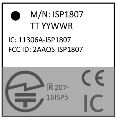
6.2. Package Labelling
A label indicating the Module Part Number, Quantity, Date Code, Lot Code and Country of Origin is applied to the bag, the reel and the box, whichever is applicable.
Information is available with bar code 1D according to Code 39 and bar code 2D according to Data Matrix ECC 200 from ECIA standard.
A second label on the bag is present to indicate the MSL level and packaging date.
![]() CAUTION
CAUTION ![]()
This bag contains
MOISTURE SENSITIVE DEVICES
- Calculated shelf life in sealed bag: 12 months at <40°C and <90% relative humidity (RH)
- Peak package body temperature : 260 +0/-5°C
- After baking, devices that will be subject to reflow solder or other high temperature process must
(i) Mounted within 168 hours of factory conditions < 30°C / 60% RH, or (ii) stored at < 10% RH - Devices require bake, before mounting, if: a) Humidity Indicator Card reads >10% for level 2a – 5a devices or >60% for level 2 devices when read at 23 + 5°C b) 3a or 3b are not met
- If baking is required, devices may be backed for 24 hours at 125 + 5°C
Bag Seal Date:……………………….
Note: Level and body temperature defined by IPC/JEDEC J-STD-020
6.3. Prototype Packaging
For engineering samples and prototype quantities up to 99 units, deliveries are provided in thermoformed trays.
They are delivered in vacuumed sealed pack with desiccant pack and humidity sensors. Please see section 7.2 for more information on moisture sensitivity.
Please order with “ST” code packaging suffix.
6.4. Jedec Trays
For pre-production volumes, ISP1807 are available in Jedec trays. They are delivered in vacuumed sealed pack with desiccant pack and humidity sensors. These Jedec trays are also suitable for further baking.
Please see section 7.2 for more information on moisture sensitivity.
Please order with “JT” code packaging suffix.
Refer to tray sizes below. Complete information on Jedec trays is available on request. 
6.5. Tape and Reel
ISP1807 are also available in Tape & Reel. They are delivered in vacuumed sealed pack with desiccant pack and humidity sensors. Reels are proposed in standard quantities of 500 units (180mm / 7” reel).
Please order with “RS” code packaging suffix.
Reels are packed in a box of approximately 220 x 220 x 50 mm. 6.6. Ordering Information
(1) Please see section 5.1 and refer to the following documentation for more information on development kit and test board:
http://www.insightsip.com/fichiers_insightsip/pdf/ble/ISP1807/isp_ble_DS1807_DK.pdf
http://www.insightsip.com/fichiers_insightsip/pdf/ble/ISP1807/isp_ble_AN201101.pdf
Storage & Soldering information
7.1. Storage and Handling
![]() Keep this product away from other high frequency devices which may interfere with operation such other transmitters and devices generating high frequencies.
Keep this product away from other high frequency devices which may interfere with operation such other transmitters and devices generating high frequencies.
![]() Do not expose the module to the following conditions:
Do not expose the module to the following conditions:
- Corrosive gasses such as Cl2, H2S, NH3, SO2, or NOX
- Extreme humidity or salty air
- Prolonged exposure to direct Sunlight
- Temperatures beyond those specified for storage
![]() Do not apply mechanical stress
Do not apply mechanical stress
![]() Do not drop or shock the module
Do not drop or shock the module
![]() Avoid static electricity, ESD and high voltage as these may damage the module
Avoid static electricity, ESD and high voltage as these may damage the module
![]() ATTENTION
ATTENTION
CONSERVE PRECAUTIONFOR HANDLING ELECTROSTATIC SENSITIVE DEVICES
7.2. Moisture Sensitivity
All plastic packages absorb moisture. During typical solder reflow operations when SMDs are mounted onto a PCB, the entire PCB and device population are exposed to a rapid change in ambient temperature.
Any absorbed moisture is quickly turned into superheated steam. This sudden change in vapor pressure can cause the package to swell. If the pressure exerted exceeds the flexural strength of the plastic mold compound, then it is possible to crack the package. Even if the package does not crack, interfacial delamination can occur.
Since the device package is sensitive to moisture absorption, it is recommended to bake the product before assembly. The baking process for dry packing is 24 hours at 125°C.
ISP1807 has been tested MSL-3 according to standards. After baking, modules can be exposed to ambient room conditions (approximately 30 °C/60%RH) during 168 hours before assembly on the PCB.
![]() CAUTION
CAUTION ![]()
MOISTURE
SENSITIVE DEVICES
7.3. Soldering information
Recommendation for RoHS reflow process is according to Jedec J–STD-020 and 033 standard profiles.

| Preheat/Soak Temperature Min (Tsmin) Temperature Max (Tsmax) Time (ts) from (Tsmin to Tsmax) |
150 °C 200 °C 60-120 sec |
| Ramp-up rate (TL to Tp) | 3 °C/sec max |
| Liquidous temperature (TL) Time (tl) maintained above TL |
217 °C 60-150 sec |
| Peak package body temperature (Tn) | 260°C (+0/-5°C) |
| Classification Temperature (Tc) Time (tn) maintained above Tc-5 °C | 260 °C 30 sec |
| Ramp-down rate (Tp to TO | 6 °C/sec max |
| Time 25 °C to peak temperature | 8 mn max |
Quality & User information
8.1. Certifications
All below certificates can be downloaded on the website:
![]() Brazil: Certification ANATEL N° 04057-23-14043
Brazil: Certification ANATEL N° 04057-23-14043
![]() Canada: IC Certification n° 11306A-ISP1807
Canada: IC Certification n° 11306A-ISP1807
![]() CE: CE Certified, DoC Insight SiP Ref TR211203
CE: CE Certified, DoC Insight SiP Ref TR211203
![]() China: CMITID Certification N°2022DJ13685
China: CMITID Certification N°2022DJ13685
![]() Japan: TELEC Certified, n° 020-200037
Japan: TELEC Certified, n° 020-200037
![]() South Korea: KCC Certification n° R-C-iNs-ISP1807
South Korea: KCC Certification n° R-C-iNs-ISP1807
![]() Taiwan: NCC Certification N° CCAJ23Y10060T5
Taiwan: NCC Certification N° CCAJ23Y10060T5
![]() USA: FCC Certification n° 2AAQS-ISP1807
USA: FCC Certification n° 2AAQS-ISP1807
![]() Bluetooth SIG Declaration ID n° D046560
Bluetooth SIG Declaration ID n° D046560
![]() RoHS3 compliant
RoHS3 compliant
![]() Reach compliant
Reach compliant
![]() Minerals responsible initiative
Minerals responsible initiative
To support customers in their application certification, Insight SiP can provide test reports on request.
8.2. EC – CE Certification
This device can be operated in at least one Member State without infringing applicable requirements on the use of radio spectrum.
8.3. USA – User information
The module is labeled with its own FCC/IC. If the FCC ID/IC is not visible when the module is installed inside another device, then the outside of the device into which the module is installed must also display a label referring to the enclosed module. In that case, the final end product must be labeled in a visible area with the following:
“Contains FCC ID: 2AAQS-ISP1807”
The label of the host device should also include the below FCC Statement. When it is not possible, this information should be included in the User Manual of the host device:
“This device complies with part 15 of the FCC rules. Operation is subject to the following two conditions.
- This device may not cause harmful interference
- This device must accept any interference received, including interference that may cause undesired operation.
Caution: Any Changes or modifications not expressly approved by the party responsible for compliance could void the user’s authority to operate the equipment.”
8.4. Canada – User information
This intends to inform how to specify the IC ID of our module “ISP1807” on the product. According to Canadian standards “RSS-247” and “RSS-Gen”, the host device should have a label which indicates that it contains our module. The label should use below example wording or any similar wording that expresses the same meaning:
“Contains IC: 11306A-ISP1807”
The label of the host device should also include the below IC Statement. When it is not possible, this information should be included in the User Manual of the host device:
“This device contains license-exempt transmitter(s)/receiver that comply with Innovation, Science and Economic Development Canada’s license-exempt RSS(s). Operation is subject to the following two conditions:(1) This device may not cause interference. (2) This device must accept any interference, including interference that may cause undesired operation of the device.
8.5. RF Exposure Information
This equipment complies with FCC RF radiation exposure limits set forth for an uncontrolled environment
If RF exposure statements and use conditions are not provided, then the host product manufacturer is required to take responsibility of the module through a change in FCC ID (new application).
8.6. Informations concernant l’exposition aux fréquences radio (RF)
The output power emitted by the wireless device is below the Industry Canada (IC) radio frequency exposure limit. This module has also been evaluated and demonstrated to comply with IC RF exposure limits under conditions of exposure to mobile and/or portable devices.
This device must be installed and used with a minimum of 15mm between the radiator and your body.
8.7. Discontinuity
Normally a product will continue to be manufactured as long as all of the following are true:
- The manufacturing method is still available.
- There are no replacement products.
- There is demand for it in the market.
In case of obsolescence, Insight SiP will follow Jedec Standard JSD-48. A Product Discontinuation Notice (PDN) will be sent to all distributors and made available on our website. After this, the procedure goes as follows:
- Last Order Date will be 6 months after the PDN was published.
- Last Shipment Date will be 6 months after Last Order Date, i.e. 12 months after PDN.
8.8. Disclaimer
Insight SiP’s products are designed and manufactured for general consumer applications, so testing and use of the product shall be conducted at customer’s own risk and responsibility. Please conduct validation and verification and sufficient reliability evaluation of the products in actual condition of mounting and operating environment before commercial shipment of the equipment. Please also pay attention (i) to apply soldering method that don’t deteriorate reliability, (ii) to minimize any mechanical vibration, shock, exposure to any static electricity, (iii) not to overstress the product during and after the soldering process.
The products are not designed for use in any application which requires especially high reliability where malfunction of these products can reasonably be expected to result in personal injury or damage to the third party’s life, body or property, including and not limited to (i) aircraft equipment, (ii) aerospace equipment, (iii) undersea equipment, (iv) power plant control equipment, (v) medical equipment, (vi) transportation equipment, (vii) traffic signal equipment, (viii) disaster prevention / crime prevention
equipment.
The only warranty that Insight SiP provides regarding the products is its conformance to specifications provided in datasheets. Insight SiP hereby disclaims all other warranties regarding the products, express or implied, including without limitation any warranty of fitness for a particular purpose, that they are defect-free, or against infringement of intellectual property rights. Insight SiP customers agree to indemnify and defend Insight SiP against all claims, damages, costs and expenses that may be incurred, including without any limitation, attorney fees and costs, due to the use of products.
The information contained is the property of Insight SiP and is provided for use by customers only.
Specification subject to change without notice.
![]()
![]() www.insightsip.com
www.insightsip.com
Document reference
isp_ble_DS1807_user_manual
Documents / Resources
 |
INSIGHTSIP ISP1807 Built In Antenna Low Energy Module [pdf] Owner's Manual ISP1807, ISP1807 Built In Antenna Low Energy Module, Built In Antenna Low Energy Module, Antenna Low Energy Module, Low Energy Module, Module |