 IEC LB2669-001 Reaction Tester with Decision Function
 Description
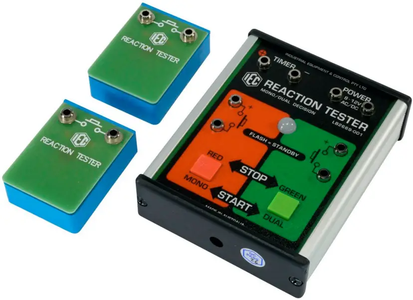
The IEC Reaction Tester is a robust instrument used to test the reaction time of a person. It runs from a 240/12V AC. PlugPak or any 8 to 12V.AC/DC classroom power supply. It is supplied with 2x very robust remote press buttons with 4mm socket connections. These buttons can be operated by hand or foot. A large LED light illuminates either RED or GREEN as an indicator, nd/or the internal BEEPER can be used. Controls are arranged around the panel for the following functions:
- Socket for 240/112V AC PlugPak on the end panel, and also banana sockets for power in.
- Sockets for a digital timer that runs when its contacts are closed and stops when its contacts are open (Photogate mode). Any IEC timer would be suitable, including the LCD model LB4057-001 or the LED model LB4064-101.
- RED press button on the panel for the user to self-initiate the mono decision mode.
- GREEN button on the panel for the user to self-initiate the dual decision mode.
- Sockets for remote press buttons to duplicate panel buttons. These remote buttons can be used at floor level as controls for starting and stopping an imaginary motor vehicle.
The Complete Instrument Consists
- 1x Instrument complete as described above with a large ‘LED’ LIGHT of dual colour and a beeper that can be used either with the LIGHT or separately.
- 2x Robust remote press buttons with 4mm sockets to permit involvement of another person for either initialising a test, OR to make the reaction time by foot control rather than by hand. When the buttons are pressed by foot, the instrument can become a ‘Driving Reaction’ tester.
Dimension
- Length: 123mm
- Width: 100mm
- Height: 35mm
- Weight: 230g
Modes of Operation
There are three modes of operation. At the end of a time delay of random length, the signal can be programmed to energise the following:
- The large RED/GREEN LIGHT only
- The internal BEEPER only
- Both the LIGHT and the BEEPERare operating together.
To set the LIGHT only to be the signal
Press and hold depressed the RED MONO button until the RED light appears. The LIGHT is now the only signal device.
To set the BEEPER only to be the signal
Press and hold depressed the GREEN DUAL button until the BEEPER sounds. The BEEPER is now the only signal device. When initiating and stopping the Reaction Test, the red and green buttons are used as normal, but the beeper tone represents the colors. When performing the dual decision reaction test using the beeper, the LOW TONE is the RED colour and the HIGH TONE is the GREEN colour.
To Set the LED and BEEPER Together to be the Signal
Press and hold depressed both the RED and GREEN buttons until both the light andthe beeper sound. The LIGHT and BEEPER operating together are now the signals.
NOTE: These details are provided on a label on the rear of the instrument for ‘easy to find’ information.
The Random Time Feature
A feature of the IEC Reaction Timer is ‘random time’. A random time delay, anywhere between 2 and 8 seconds, is initiated by pressing either a panel button or a remote button connected to the 4mm sockets. This means that instead of requiring a second person to start the timer, the person under study can simply ‘click’ a button to initiate his/her test, which will begin at an unknown time from this first button press.
Mono Decision
- In ‘standby’, the LIGHT is flashing. If the RED button marked START (MONO) is clicked, an unknown time delay begins, and the LIGHT is OFF.
- When the unknown time delay has expired, the RED LIGHT is ON. The timer connected to the sockets starts timing,g and the SAME RED button must be pressed by the person as quickly as possible to stop the timer and bring the system to ‘standby’ (LIGHT flashing again).
- The timer will display the reaction time. Ithe f button is not pressed, or the wrong button is pressed, the system resets back to ‘standby’ and the timer shows the total time.
- The mono decision is: Is the RED LIGHT on?
Dual Decision
- In ‘standby’, the LIGHT is flashing. If the GREEN button marked START (DUAL) is pressed, an unknown time delay begins, and the LIGHT is OFF.
- When the unknown time delay has expired, EITHER the RED OR GREEN LIGHT can randomly be ON.
- The timer connected to the sockets starts timing and, if it is the REDLIGHT is on, the RED BUTTON must be pressed, OR if the GREEN LIGHT is on, the GREEN BUTTON must be pressed as quickly as possible to stop the timer and to bring the system to ‘standby’ (LIGHT flashing again).
- The timer will display the reaction time. If the button is not pressed, or the wrong button is pressed, the system resets back to ‘standby’ and the timer shows the total time.
The dual decisions are
- Is the LIGHT on
- Which color is it?
- If the RED button is used to start the test, the RED light (or low pitch beeper tone) is ON at the end of a random time, and the RED button MUST be pressed to stop the timer.
- If the GREEN button is used to start the test, the light at the end of the random time could be either RED (low pitch beeper tone) OR GREEN (high pitch beeper tone).
- If RED, then the RED button MUST be pressed to stop the timer. If GREEN, then the GREEN button MUST be pressed to stop the timer.
- If the wrong colour is pressed, it is a ‘FAIL’ and the situation cannot be corrected. The timer continues for several seconds and then automatically reverts to ‘standby’. The timer shows this total time.
The Remote Press Buttons
The remote press buttons in the kit are strong and can be used by pressing with the foot. The buttons on the panel and the remote buttons have exactly the same functions. Either can be used to initiate the random time delay and also to react to the LIGHT or BEEPER signal.
Driver Reaction Test using Remote Buttons
The strong remote buttons can be taped to a wooden block or otherwise adapted to foot operation to simulate the operation of the brake pedal for a driving reaction test while the driver sits in a chair pretending to drive.
However, to protect the buttons against heavy and total destruction, it is recommended that the ‘Driving Reaction’ tests be done with soft-soled shoes or with a shoe removed.
Cheating
- With the intention of cheating the system, it has been known for students to quickly and repetitively press the button to try to stop the timer faster than it would normally stop for a genuine reaction time.
- In the IEC Reaction Timer, if a button is pressed BEFORE the random time has expired, the random and unpredictable time delay immediately resets. This feature avoids cheating.
- When the Reaction Timer has been stopped in the correct manner and by the correct button, the LIGHT enters the ‘standby mode’ and remains flashing until another test is initiated.
- If the button is not pressed, or the wrong button is pressed, the system will not accept a ‘change of mind’ and automatically reset back to ‘standby’.
Spare Parts: Spare Remote Press Buttons: PA2669-050
Ancillary equipment required
- A standard 240/112V AC PlugPak or any 8 to 12V.AC or DC power source.
- A fast digital timer that will RUN with contacts closed and STOP whenthe contacts open circuit.
- Almost all IEC timers have a PhotoGate mode, which operates in this manner. Suitable IEC timers are LB4057-001 and LB4064-101 or similar.
Designed and manufactured in Australia
FAQs
Q: How do I switch between different modes of operation?
A: To switch between modes, follow the instructions provided for each mode in the manual. Press and hold the corresponding buttons as directed.
Q: Can I use the Reaction Tester without connecting it to a power supply?
A: No, the Reaction Tester requires either a 240/12V AC PlugPak or an 8 to 12V AC/DC power supply to function properly.
Documents / Resources
 |
IEC LB2669-001 Reaction Tester with Decision Function [pdf] Instruction Manual LB2669-001, LB2669-001 Reaction Tester With Decision Function, LB2669-001, Reaction Tester With Decision Function, With Decision Function, Decision Function, Function |