![]() FID BENCH
FID BENCH
WITH ARM AND LEG DEVELOPER OWNERS MANUAL | F-MR-FID-V2
PARTS LIST
| KEY NUMBER | DESCRIPTION OF PART | QUANTITY |
| 1 | Back Bottom Beam Assembly | 1 |
| 2 | Main Beam Tube Assembly | 1 |
| 3 | Guide Rod Washer | 2 |
| 4 | Flat Washer φ12 | 2 |
| 5 | Lock Nut M12 | 2 |
| 6 | Hexagon Bolt M10*120 | 2 |
| 7 | Gear Plate | 2 |
| 8 | Flat Washer φ10 | 19 |
| 9 | Lock Nut M10 | 10 |
| 10 | Hexagon Bolt M10*80 | 4 |
| 11 | Seat Tube Assembly | 1 |
| 12 | Back Cushion Tube Assembly | 1 |
| 13 | Back Cushion Back Support Assembly | 1 |
| 14 | External Thread Shaft φ12*M10*118 | 1 |
| 15 | Shaft φ12*129.5-M10 | 1 |
| 16 | Seat Cushion | 1 |
| 17 | Back Cushion | 1 |
| 18 | Flat Washer φ8 | 13 |
| 19 | Spring Washer φ8 | 13 |
| 20 | Hexagon Bolt M8*60 | 5 |
| 21 | Kick Internal Insert Tube Assembly | 1 |
| 22 | Kick Frame Assembly | 1 |
| 23 | Foam Inner Cap φ70*φ27*12 | 6 |
| 24 | Foam Outer Cap φ70*φ9*14 | 6 |
| 25 | Foam φ25*φ100*175 | 6 |
| 26 | Hexagon Socket Button Head Screw M8*25 | 6 |
| 27 | Foam Tube | 3 |
| 28 | T Shape Pin φ10*85 | 1 |
| 29 | Internal Thread Shaft φ20*57-M10 | 1 |
| 30 | Spring Washer φ10 | 4 |
| 31 | Hexagon Bolt M10*25 | 4 |
| 32 | Olympic Lock Collar | 1 |
| 33 | Chest Cushion Tube | 1 |
| 34 | Barbell Support Tube | 1 |
| 35 | Chest Cushion | 1 |
| 36 | Big Flat Washer φ30*φ10*3 | 2 |
| 37 | Hexagon Bolt M10*70 | 2 |
| 38 | Hexagon Bolt M8*20 | 8 |
| 39 | Moving Roller | 2 |
| 40 | Tube Plug 50-60 | 1 |
| 41 | Pull Pin M18*22*φ10 | 1 |
| 42 | Pull Pin φ12*M20*75 | 1 |
| 43 | Foot Cover F150 | 1 |
| 44 | Tube Plug φ40*80*2 | 2 |
| 45 | Powder Powder Sleeve φ22*φ18*φ12.2*15 | 2 |
| 46 | Back Support Rubber Pad | 1 |
| 47 | Tube Plug φ25*2 | 2 |
| 48 | Hexagon Socket Countersunk Head Screw M6*16 | 4 |
| 49 | Internal Thread Shaft φ16*95-M12 | 1 |
| 50 | Reduction Sleeve φ32*φ26*25 | 8 |
| 51 | Rubber Shock Pad φ50*50*30 | 1 |
| 52 | Powder Powder Sleeve φ32*φ29*φ20*18 | 2 |
| 53 | Countersunk Hexagon Rivet Nut M10 | 1 |
| 54 | Hexagon Socket Countersunk Head Screw M10*30 | 1 |
| 55 | Sleeve | 1 |
| 56 | Two Layer Spring Nut φ23-M8 | 6 |
| 57 | Roller Wheel Shaft φ14.9*45-M8 | 2 |

ASSEMBLY
STEP 1
| KEY NUMBER | DESCRIPTION OF PART | QUANTITY |
| 1 | Back Bottom Beam Assembly | 1 |
| 2 | Main Beam Tube Assembly | 1 |
| 3 | Guide Rod Washer | 2 |
| 4 | Flat Washer φ12 | 2 |
| 5 | Lock Nut M12 | 2 |
| 6 | Hexagon Bolt M10*120 | 2 |
| 7 | Gear Plate | 2 |
| 8 | Flat Washer φ10 | 8 |
| 9 | Lock Nut M10 | 4 |
| 10 | Hexagon Bolt M10*80 | 4 |
ASSEMBLY DRAWING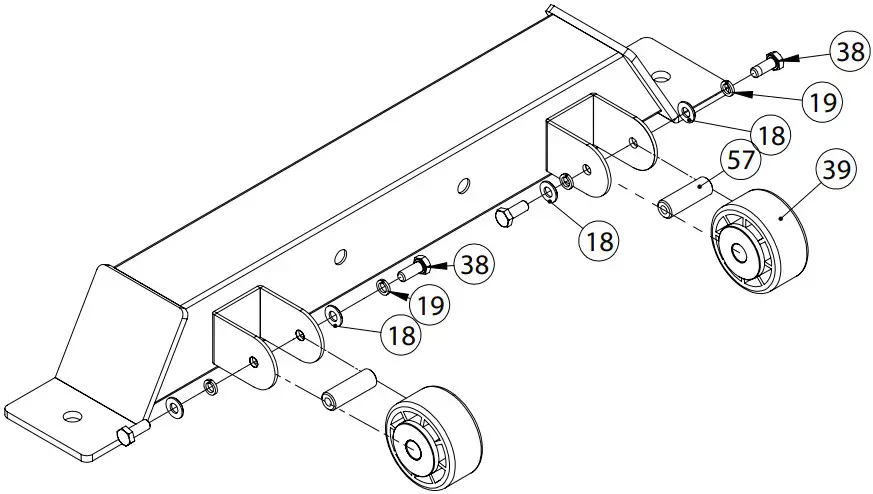
| KEY NUMBER | DESCRIPTION OF PART | QUANTITY |
| 18 | Flat Washer φ8 | 4 |
| 19 | Spring Washer φ8 | 4 |
| 38 | Hexagon Bolt M8*20 | 4 |
| 39 | Moving Roller | 2 |
| 57 | Roller Wheel Shaft φ14.9*45-M8 | 2 |
ASSEMBLY DRAWING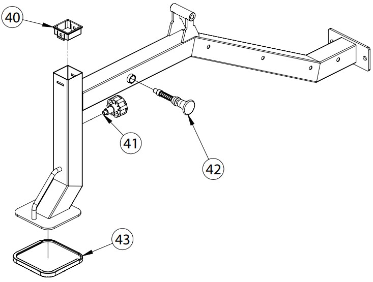
| KEY NUMBER | DESCRIPTION OF PART | QUANTITY |
| 40 | Tube Plug 50-60 | 1 |
| 41 | Pull Pin M18*22*φ10 | 1 |
| 42 | Pull Pin φ12*M20*75 | 1 |
| 43 | Foot Cover F150 | 1 |
ASSEMBLY DRAWING
ASSEMBLY INSTRUCTIONS
- Connect back bottom beam assembly-1 and main beam tube assembly-2 use M10*120 hexagon bolt-6, φ12 flat washer-4, guide rod washer-3 and M12 lock nut-5.
- Connect gear plate-7 and main beam tube assembly-2 use M10*80 hexagon bolt-10, φ10 flat washer-8 and M8 lock nut-9.
STEP 2
| KEY NUMBER | DESCRIPTION OF PART | QUANTITY |
| 8 | Flat Washer φ10 | 4 |
| 9 | Lock Nut M10 | 4 |
| 11 | Seat Tube Assembly | 1 |
| 12 | Back Cushion Tube Assembly | 1 |
| 13 | Back Cushion Back Support Assembly | 1 |
| 14 | External Thread Shaft φ12*M10*118 | 1 |
| 15 | Shaft φ12*129.5-M10 | 1 |
ASSEMBLY DRAWING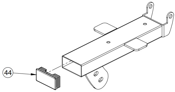
| KEY NUMBER | DESCRIPTION OF PART | QUANTITY |
| 44 | Tube Plug φ40*80*2 | 1 |

| KEY NUMBER | DESCRIPTION OF PART | QUANTITY |
| 44 | Tube Plug φ40*80*2 | 1 |
| 45 | Powder Powder Sleeve φ22*φ18*φ12.2*15 | 2 |
ASSEMBLY DRAWIN
| KEY NUMBER | DESCRIPTION OF PART | QUANTITY |
| 8 | Flat Washer φ10 | 2 |
| 30 | Spring Washer φ10 | 2 |
| 31 | Hexagon Bolt M10*25 | 2 |
| 46 | Back Support Rubber Pad | 1 |
| 47 | Tube Plug φ25*2 | 2 |
| 48 | Hexagon Socket Countersunk Head Screw M6*16 | 4 |
| 49 | Internal Thread Shaft φ16*95-M12 | 1 |
ASSEMBLY DRAWING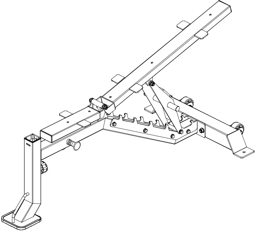 ASSEMBLY INSTRUCTIONS
- Fix seat tube assembly-11 and back cushion tube assembly-12 on main frame use φ 12*M10*118 external thread shaft-14, φ10 flat washer-8 and M8 lock nut-9.
- Connect back cushion tube assembly-12 and back cushion back support assembly-13 use φ 12*129.5-M10 shaft-15, φ10 flat washer-8 and M8 lock nut-9.
STEP 3
| KEY NUMBER | DESCRIPTION OF PART | QUANTITY |
| 16 | Seat Cushion | 1 |
| 17 | Back Cushion | 1 |
| 18 | Flat Washer φ8 | 5 |
| 19 | Spring Washer φ8 | 5 |
| 20 | Hexagon Bolt M8*60 | 5 |
ASSEMBLY DRAWING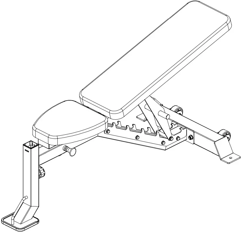 ASSEMBLY INSTRUCTIONS
- Fix seat cushion-16 and back cushion-17 use M8*60 hexagon bolt-20, φ8 spring washer-19 and φ8 flat washer-18.
STEP 4
| KEY NUMBER | DESCRIPTION OF PART | QUANTITY |
| 8 | Flat Washer φ10 | 2 |
| 21 | Kick Internal Insert Tube Assembly | 1 |
| 22 | Kick Frame Assembly | 1 |
| 23 | Foam Inner Cap φ70*φ27*12 | 6 |
| 24 | Foam Outer Cap φ70*φ9*14 | 6 |
| 25 | Foam φ25*φ100*175 | 6 |
| 26 | Hexagon Socket Button Head Screw M8*25 | 6 |
| 27 | Foam Tube | 3 |
| 28 | T Shape Pin φ10*85 | 1 |
| 29 | Internal Thread Shaft φ20*57-M10 | 1 |
| 30 | Spring Washer φ10 | 2 |
| 31 | Hexagon Bolt M10*25 | 2 |
| 32 | Olympic Lock Collar | 1 |
ASSEMBLY DRAWING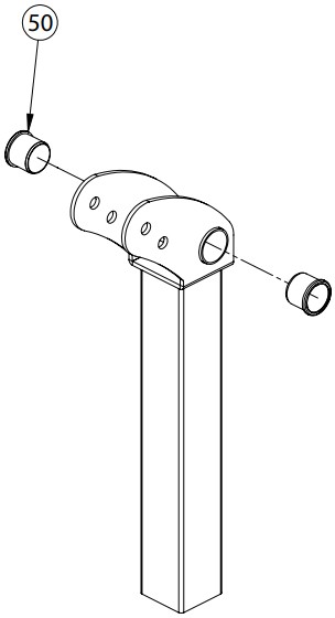
| KEY NUMBER | DESCRIPTION OF PART | QUANTITY |
| 50 | Reduction Sleeve φ32*φ26*25 | 2 |

| KEY NUMBER | DESCRIPTION OF PART | QUANTITY |
| 56 | Two Layer Spring Nut φ23-M8 | 2 |
ASSEMBLY DRAWING

| KEY NUMBER | DESCRIPTION OF PART | QUANTITY |
| 8 | Flat Washer φ10 | 1 |
| 50 | Reduction Sleeve φ32*φ26*25 | 6 |
| 51 | Rubber Shock Pad φ50*50*30 | 1 |
| 52 | Powder Powder Sleeve φ32*φ29*φ20*18 | 2 |
| 53 | Countersunk Hexagon Rivet Nut M10 | 1 |
| 54 | Hexagon Socket Countersunk Head Screw M10*30 | 1 |
| 55 | Sleeve | 1 |
ASSEMBLY DRAWING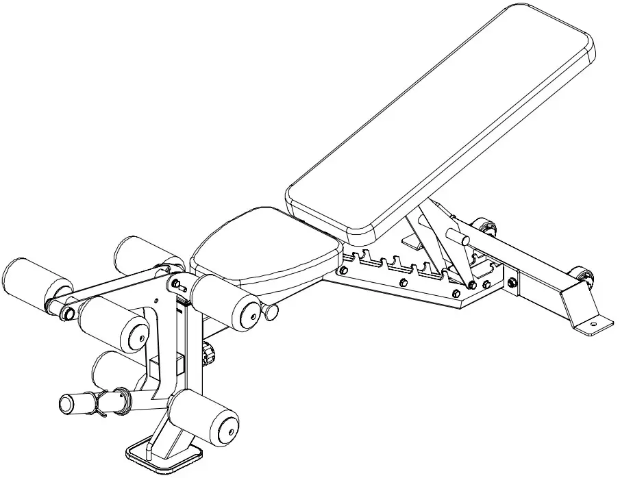 ASSEMBLY INSTRUCTIONS
- Connect kick internal insert tube assembly-21 and kick frame assembly-22 use M10*25 hexagon bolt-31, φ10 spring washer-30, φ10 flat washer-8 and φ20*57-M10 internal thread shaft-29.
- Fix foam-25 and foam tube-27 on kick internal insert tube assembly-21 and kick frame assembly-22 use M8*25 hexagon socket button head screw-26, foam inner cap-23 and foam outer cap-24.
- Install olympic lock collar-32 on kick frame assembly-22.
STEP 5
| KEY NUMBER | DESCRIPTION OF PART | QUANTITY |
| 8 | Flat Washer φ10 | 2 |
| 9 | Lock Nut M10 | 2 |
| 18 | Flat Washer φ8 | 4 |
| 19 | Spring Washer φ8 | 4 |
| 33 | Chest Cushion Tube | 1 |
| 34 | Barbell Support Tube | 1 |
| 35 | Chest Cushion | 1 |
| 36 | Big Flat Washer φ30*φ10*3 | 2 |
| 37 | Hexagon Bolt M10*70 | 2 |
| 38 | Hexagon Bolt M8*20 | 4 |
ASSEMBLY DRAWING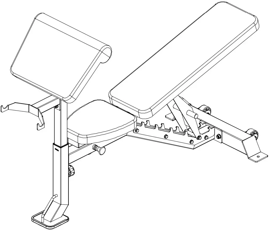
ASSEMBLY INSTRUCTIONS
- Connect chest cushion tube-33 and barbell support tube-34 use M10*70 hexagon bolt-37, big flat washer-36, φ10 flat washer-8 and M8 lock nut-9.
- Fix chest cushion-35 on chest cushion tube-33 use M8*20 hexagon bolt-38, φ8 spring washer-19 and φ8 flat washer-18.
![]()
Documents / Resources
 |
FORCE F-MR-FID-V2 FID Bench with Arm and Leg Developer [pdf] Owner's Manual F-MR-FID-V2 FID Bench with Arm and Leg Developer, F-MR-FID-V2, FID Bench with Arm and Leg Developer, Arm and Leg Developer, Leg Developer, Developer |