![]() DVDO-CS-1
DVDO-CS-1
Conference System with USB-C &
HDMI Inputs and Built-in DSP
User Manual
Version v1.0 
Overview
DVDO-CS-1 is an AV conference system with USB-C and HDMI inputs, USB host and device ports and dual HDMI output.
It includes a built-in DSP with two microphone inputs, two line-in inputs and two line-in outputs as well as a 2x20W amplifier with speaker output.
It can be controlled over IP with an intuitive web GUI allowing to configure various video and audio settings.
The signal processing allows configuration and control for routing, mixing, filtering, ducking, equalization, delay and echo cancellation.
Hardware
2.1. Specifications
- Audio
– 2 Mic Input (with AEC), 2 gain adjusting knobs
– 2 Line input
– 2 Line output
– 2 Power amplifiers Output (approx. 20W, 8Ω constant resistance) - Video
– 1 HDMI input for laptop connection
– 2 HDMI outputs for display connection
– 2 USB 3.0 Type-A ports for camera connection - BYOD
– 1 USB Type-C port for laptop connection
– 1 USB Type-B port for laptop connection - Control
– 1 RESET button for restoring factory Settings
– 1 Ethernet port to configure the interface
– 1 Running status indicator
– 1 Input source switch button
– 2 Input source indicators - Power supply
– DC 18V, 6A
– Power switch
2.2. Front Pannel

| Name | Description |
| POWER button | Power switch |
| RUN LED | The indicator blinks slowly, the system is running properly |
| TYPE-C LED | The indicator light is on, indicating that the computer or VC device is connected through TYPE-C |
| HOST LED | The indicator light is on, indicating that the computer or VC device is connected through HOST |
| TOGGLE button | Push the button and select TYPE-C/HOST input sources |
| TYPE-C | Connect computer or VC device for audio/video, support USB3.2 |
| HOST | Connect computer or VC device for audio/video, support USB3.2 |
| HDMI IN | HDMI 2.0 port, connect to HDMI video source |
| HDMI OUT 1/2 | 2 X HDMI 2.0, connect to display |
| USB 3.0 | 2 X USB-A, connect to camera, 5V @ 500mA, supports USB3.2 |
2.3. Rear Pannel

| Name | Description |
| RESET button | Push and hold the Reset button 3s to restore factory Settings |
| ETHERNET port | Connect to configurate PC |
| MIC 1/2 knob | MIC1/2 gain adjustment knob |
| MIC IN 1/2 | 2 balanced MIC input with AEC |
| LINE IN 3/4 | 2 balanced LINE input |
| LINE OUT 1/2 | 2 balanced LINE output |
| SPEAKER OUTPUT L/R | Power amplifier output port |
| DC-18V | Power port |
Device Connection and Use
3.1. Video conferencing using BYOD is supported
Using a single USB port, BYOD devices such as a PC can be connected to AV peripherals such as monitors, speakers, microphones and cameras in the room, making it easy to convert a personal desktop into a professional conference room. The Conference box has two connections to the PC to transmit audio, video, and content:
- Connect with USB Type-C port only.
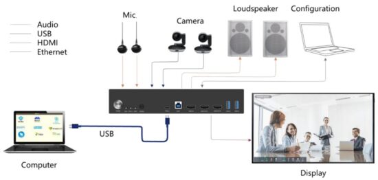
- Use USB Type-B port and HDMI IN port for connection.

3.2. Supports local display
BYOD devices can also extend the signal from a computer to a local display through a USB cable, making them extremely convenient super meeting terminals.
The Conference box and computer can be connected in two ways to the display:
- Connect with USB Type-C port only.

- Use USB Type-B port and HDMI IN port for connection.

3.3. Microphone Input gain adjustment
In actual use, different microphones have different sensitivity. In order to match different microphones, gain adjustment function is provided on the processor panel.
There are two microphone Input gain adjustment knobs on the upper part of the processor rear panel, as shown in the figure:

When adjusting the gain, the clockwise direction is to increase the gain, and the counterclockwise direction is to reduce the gain.
3.4. Audio processor commonly used joint conversion
3.4.1. 3.5mm stereo audio cable (Small three core) to Phoenix terminal
3.5mm audio cable, commonly known as small three core. The 3.5mm audio plug is an unbalanced signal plug. Phoenix terminal is a balance terminal, then when the conversion, there are two cases:
The first case: 3.5mm stereo audio cable is Output, and the Phoenix terminal is connected to the equipment Input.
3.5mm stereo terminal has three audio cables, generally speaking, the left channel is the white line, the right channel is the red line, the peripheral bare wire is the ground, the ground is shared. When Linkage Phoenix head Input, the white line is connected to the positive pole of a phoenix terminal, and the ground wire is connected to the negative and ground of this Phoenix terminal at the same time. The red line is connected to the positive pole of another Phoenix terminal, and the ground line is connected to the negative and ground of the Phoenix terminal at the same time (that is, the negative and ground should be short-connected). See the following diagram:

The second case: Phoenix terminal is connected to the device Output, 3.5mm stereo audio line is Input.
When the Phoenix terminal Output Linkage 3.5mm audio line input, the left channel white line connects to the positive pole of a Phoenix terminal, the peripheral ground wire connects to the ground of the Phoenix terminal, and the negative is suspended. The red line of the right channel is connected to the positive pole of another Phoenix terminal, and the peripheral ground is connected to the ground of the Phoenix terminal, and the negative hanging. See the following diagram:

3.4.2. RCA audio cable (Lotus head) to Phoenix terminal
RCA audio cable, commonly known as Lotus Head. RCA audio cable is an unbalanced signal plug. Phoenix terminal is a balance terminal, then when the conversion, also divided into two cases:
The first case: RCA audio wire connected to the device Output, Phoenix terminal connected to the device Input.
A Lotus head wire has two wires: a signal wire and a ground wire. When Linkage Phoenix head Input, the signal line is connected to the positive pole of a Phoenix terminal, and the ground wire is connected to the negative and ground of the Phoenix terminal at the same time (that is, the negative and ground should be shortconnected). See the diagram below:

The second case: RCA audio wire is connected to the device Input, and the Phoenix terminal is connected to the device Output
When Linkage Phoenix head Output, the signal line is connected to the positive pole of a phoenix terminal, and the ground wire is connected to the ground of the Phoenix terminal, and the negative is suspended. See the diagram below:

3.4.3. XLR audio cable (Cannon head) to Phoenix terminal
XLR audio cable, commonly known as Canon head. XLR audio cable is a kind of balanced signal plug. Phoenix terminal is also a balanced terminal, then the connection is only one case, the diagram is as follows:

3.4.4. TRS audio cable (Big three core) to Phoenix terminal
TRS audio cable, commonly known as big three core. TRS audio cable is a kind of balanced signal plug. Phoenix terminal is also a balanced terminal, then the connection is only one case, the diagram is as follows:

Software
4.1. Software Download
Device connection and configuration
The default IP address for the processor is: 192.168.1.100. The subnet mask is: 255.255.255.0. Make sure both the PC and the processor are on the same network segment of the same local area network. If the PC is not on the same network segment as the processor, go to the PC network Settings to modify the network parameters.
Software Download
After the previous step, open the browser on the PC and Input “192.168.1.100” to open the software download page. To log in, Input user name “admin”, password “123456” and click “Login”. Download the installer according to the prompts (some models need to choose to download PC software), and install it after the download is completed.
4.2. Using the Software
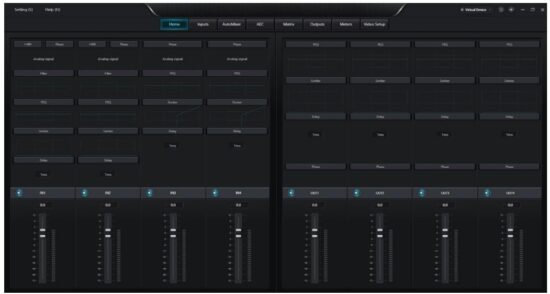
After opening the software, display the home screen:
Clicking the button “Virtual Device” ![]() in the upper right corner of the main interface will automatically find all the processors on the network, and the user will connect to the specified processor as needed. After the connection is successful, the indicator is on, and the name of the connected device is displayed.
in the upper right corner of the main interface will automatically find all the processors on the network, and the user will connect to the specified processor as needed. After the connection is successful, the indicator is on, and the name of the connected device is displayed. ![]()
Connection status judgment:

(such as: device switch signal source, computer network card switch and USB line disconnection between the device and the computer, etc.).
In the Connection state, click the button ![]() in the upper right corner to restore the device to factory Settings. Clicking the button
in the upper right corner to restore the device to factory Settings. Clicking the button ![]() in the upper right corner will mute all Output channels on the device.
in the upper right corner will mute all Output channels on the device.
4.3. Audio Module Parameters
4.3.1. Input Source

Phantom power supply: Feed the external capacitive microphone, enabled when connected to the microphone. Do not open without power supply, in case of damage to external equipment.
Invert: The phase of the audio signal is reversed 180°.
Mute: Mute the channel.
Sine Wave: Adjust the frequency to produce a sine wave at the specified frequency (20 to 20 KHz). The Output level can be adjusted as required in dBFS. Use the knob to adjust or click the text Input box to specify a value.
White Noise: White noise has equal energy in each frequency component. Observe it on a spectrum meter with constant bandwidth, it has a flat spectrum. At this point the frequency adjustment is ineffective and the level is available.
Pink Noise: The frequency component power of pink noise is mainly distributed in the middle and low frequency bands, where it decreases at a rate of 3dB/Oct over the spectrum. At this time, the frequency adjustment is not effective and the level is available.
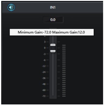
In addition, in the main interface, each fader can control the gain of the corresponding channel. Clicking ![]() can mute the channel. Right click on the fader to see the following menu Settings: Minimum Gain and Maximum
can mute the channel. Right click on the fader to see the following menu Settings: Minimum Gain and Maximum
Gain: Limit the maximum and minimum gain of this channel.
4.3.2. Limiter
The limiter is used to ensure that the signal does not exceed the threshold level under any circumstances.

Threshold: Set the maximum sound threshold. Any sound above the threshold will be limited to the set threshold.
Release time: The time it takes to lift the limit.
4.3.3. PEQ
The primary purpose of an equalizer is to correct for overemphasized or missing frequency ranges, whether they are wide or narrow. In addition, the equalizer can also help us narrow or widen the frequency range, or change the magnitude of certain components of their frequency spectrum. In simple terms, an equalizer changes the timbre of a signal.

The equalizer has the following control parameters:
Frequency (Hz): The center frequency of the filter.
Gain (dB): The value of the gain boost or attenuation in decibels at the center frequency position.
OCT: Adjust the influence range of the corresponding node, 0.01 is the smallest influence range, 4 is the largest.
There is a switch under each section of the equalizer, which means to open or close the section. When closed, the parameter settings of each section have no effect. The equalizer has a master switch to enable or disable the module.
4.3.4. Ducker
When the level value of the reference signal channel exceeds a specified threshold, the level of the channel on which the ducker is set is attenuated.
This is the purpose of the ducker.

REF signal: The reference signal selected by the Ducker can choose channel 1-4 as the reference signal.
Threshold: The reference signal starts to decay above the threshold, and recovers below the threshold.
Depth: The amount of maximum reduction by the Ducker signal. The left fader and mute button are the amount of attenuation, and the maximum attenuation is the depth control.
Attack time: After the reference signal is above the threshold, the time it takes to attenuate the signal to the specified value.
Release time: The time it takes for the Ducker signal to return to its original signal size after the reference signal is below the threshold.
4.3.5. Auto Mixer
In a conference room, if multiple microphones are turned on to the same gain level and only one person is speaking, the result may not be very clear, the other microphones will pick up room noise, reverberation, etc., when these signals are mixed with the normal microphone signal, it will greatly reduce the quality of the mixed audio Output. In order to solve this problem, it is necessary to turn off other microphones that are not in use for the time being. An automatic mixer can do this for you, and it will be faster than doing it manually.
A gain-sharing automatic mixing module is built into the processor, which supports the Input of two microphone channel.

The automatic mixing module has two sets of control parameters:
- Main control parameters
Gain: Controls auto mix main Output volume
Slope: The slope controls the attenuation that affects lower levels. At higher slopes, low channel are attenuated more.
When the slope is set to 2.0, it can achieve more ideal gain sharing and is the preferred value in use.
Response time: A faster time ensures that the head of the spoken word is not cut off. The operation is more smoothing when the time is slow. Practice shows that the response time is around 400ms for the best results. Autogain is designed to turn the microphone on much faster than it is turned off, so even with a 400ms response, the head of the spoken word is usually not subtracted. If you set a slower time of a few seconds, the auto mixer response time will have a longer hold time, and the last active channel will save the open state for a few seconds.
Mute: Automatic mixing Channel can be muted.
- Channel control parameter
Auto Mix: Each Channel has an auto mix on/off button that needs to be turned on for channel participating in auto mix. It can also be turned off, and the channel does not participate in automatic mixing.
Mute: Mute the channel, but does not affect the channel’s output sound through auto mix
Gain: Adjust the gain fader to increase/decrease the proportion of volume in automatic mixing.
Priority: Setting a priority can override a high-priority Channel over a low- priority channel, thereby affecting the automatic mixing algorithm. The parameter ranges from 0 to 10. The larger the value, the higher the priority.
Priority control allows high priority channel to coverage low priority channel, thus affecting the automatic mixing algorithm. The control can take on a range of values from 0 (lowest priority) to 10 (highest priority), with a default value of 5 (standard priority). You can adjust the priority by using the slider, or you can Input a specified priority between 0 and 10 by clicking the edit box. Increasing this numeric value increases the priority.
If two size of the same signal level size, the channel with a higher priority will have a higher automatic gain. If two channel differ by one unit of priority, the channel with one higher priority gains an additional 2dB (Hypothesis the slope of both channel is set to 2.0) of automatic mixing gain. For example, if the priority of IN1 is set to 6 and the priority of IN2 is set to 3, the two channel Input levels have the same magnitude, and IN1 will get an additional mixing gain of 6dB over IN2. Note that the slope setting of the main control parameter will also affect the difference in mixing gain caused by the channel’s preferred weight. If the slope is set to 3.0, then a priority unit difference between channel results in a gain difference of 4dB. If all channel have the same priority, leave all settings at the default level 5.
Note: Extreme priority differences between channel, such as 0 and 10, need to be used with extreme care in some settings. If a very high priority channel is picking up signals from the speaker, such as background noise, it is possible to mask a lower priority channel, even if the very high priority channel is not in use, the higher the slope of the problem is more serious.
4.3.6. Echo Cancellation
Acoustic Echo Cancellation or AEC is a digital audio signal processing technique used for audio and video teleconference when the conversation takes place between participants in a local conference room and one or more speakers at a certain distance. AEC programs increase the phonetic of remote speakers by eliminating acoustic echoes generated in the local room.
The echo cancellation module applied in remote call can facilitate local amplification of remote phonetic signal and damping off the interference of acoustic echo. Its basic working principle is to simulate the echo channel, estimate the echo that may be formed by the remote signal, and then subtract the estimated signal from the Input signal of the microphone, so that the Input phonetic signal no longer contains the echo, in order to achieve the purpose of echo elimination.

The echo cancellation module presets the local Input and remote Input mixing channel to realize multiple signals participating in echo cancellation, as shown in the figure. Parameter are as follows:
Echo Cancellation: Conservative, Moderate, and Aggressive are available.
Correspond to the echo cancellation effect from weak to strong, respectively.
Note:
The echo cancellation module setup needs to be used in conjunction with the Matrix module setup for signal routing.
NLP processing: Set the linear processing effect of echo cancellation. The higher the setting value, the more obvious the echo cancellation effect is, but it will cause the local Input sound to eat words. The default value of 1 is sufficient.
Remote Input: As a reference signal channel for the remote signal Input.
In addition, the echo cancellation module has the following parameters that can be set:
Noise suppression: 0 is to turn off noise suppression, there are 6dB, 10dB, 15dB and 18dB options. dB means how much dB to reduce the noise suppression. The larger the value, the greater the damage to the speech, which is unavoidable. 6-18 is the value of the reduction in noise suppression.
AGC treatment: When turned on, automatic gain control is enabled.
De-reverberation: Turn on to enable de-reverberation effects, such as the presence of reverberation in the space, turn on to slightly reduce the reverberation of the sound.
However, if the reverberation is too serious, enabling can not get a good sound effect.
4.3.7. Matrix
Matrix has the dual operation function of routing and mixing. Horizontal represents the Input channel, vertical represents the output channel, as shown in the figure. If you need to have IN3 output from OUT1 and OUT3, then the corresponding matrix at the point is sufficient.

In addition, the matrix module has the following control parameters: When right-clicking the corresponding point on the matrix, the gain size panel will pop up to adjust the point separately, as shown in the following graph.
Adjusting the fader on this panel can change the gain size.

4.3.8. High Pass & Low Pass Filter
The purpose of the high pass and low pass filter is to filter out the frequency bands outside the selected range to achieve the desired performance.

The following parameters can be adjusted:
Low pass frequency: The cutoff frequency of the filter, below the set frequency can be passed.
High pass frequency: The cutoff frequency of the filter, above which the set frequency can pass.
4.3.9. Delay

When the delay module is enabled on the channel type, the Input sound will delay the output according to the parameters set.
Milliseconds: Set the delay time of the delayer. This value ranges from 1 to 500 milliseconds. Both meters and feet are unit values for millisecond conversion.
4.3.10. Output

Invert: The phase of the audio signal is reversed by 180°.
Mute: Set to mute/unmute.
4.3.11. Video
Settings
The video output configuration parameters are set uniformly to achieve the consistent display effect of HDMI1/2.

The following parameters can be set:
Manual/Automatic: In manual mode, you can click TYPE-C/HOST to switch interfaces. In automatic mode, you cannot click TYPE-C/HOST.
Note: When the interface is switched, the control software may be disconnected from the device due to changes in the network and must be re-connected if necessary. The switch interface will switch the network card and sound card at the same time.
EDID Settings: The following parameters are optional: Copy from Output 1, Copy from Output 2, 1920×1080@60Hz, 3840×2160@30Hz and 3840×2160@60Hz.
Note: If the set parameters are not supported by the display, there will be some displays that cannot be displayed normally.
Effect: After setting the EDID parameters, you need to click “Active” to make the setting effective.
4.3.12. Settings
Device Settings
Configure information such as the Name, IP address, and Gateway of the device.

DHCP: When enabled, the device will automatically obtain an IP address, without the need to manually set the IP address.
4.3.13. Help
About: Display version number, technical support contact information, copyright information, etc.
Check for updates: Check for the existence of a new version of the control softwareFirmware upgrade: Upgrades the device.

Select the device and upgrade package to be upgraded and click “Updates”. Wait for the progress bar to complete the upgrade.
4.4. USB Sound Card
Sound card Settings
Connect the device to the computer host through the Type-B/Type-C data cable. After the connection, the sound card of the current device appears in the list of playback and recording sound cards in the computer sound panel, as shown in the figure. At this time, the sound card of the processor is selected as the default value for playback and recording.

FAQ
5.1. Output no sound
- Check whether the processor RUN indicator light blinks slowly.
- Check whether the Input/output interface is correctly connected.
- Check whether the microphone input source and line input source have normal audio signals.
5.2. Output sound with current noise
- Whether the audio connection cable is made correctly.
- Whether the audio connection is connected with a shielded cable.
- Whether the input signal source level is too large.
5.3. The video source has no output
- Please check whether the use of compliant TYPE-C/HDMI data cable.
- Check whether the connected device supports TYPE-C video Output.
- Check whether the EDID parameter of the device is correctly configured. If EDID is set to Copy from Output1, check whether HDMI OUT1 is connected to the turned on monitor. If not, connect to the monitor, or try to switch EDID Parameter.
- Please check whether the display supports the current setting of EDID, if not, please try to switch EDID parameter.
- If the above methods cannot be solved, you can try unplugging and reinserting the TYPE-C/HDMI data cable.
![]() Follow us
Follow us ![]() DVDO │ +1.408.213.6680
DVDO │ +1.408.213.6680
support@dvdo.com │ www.dvdo.com
Documents / Resources
 |
DVDO DVDO-CS-1 HDMI Inputs and Built In DSP [pdf] User Manual DVDO-CS-1 HDMI Inputs and Built In DSP, DVDO-CS-1, HDMI Inputs and Built In DSP, Built In DSP, DSP |