Danfoss IP21 Type 1 Conversion Kit
Overview
Description
This installation guide explains how to install the IP21/Type 1 conversion kit for enclosure sizes MA01c, MA02c, MA01a, MA02a, and MA03a of iC2-Micro Frequency Converters.
Kit Numbers
Use these instructions with the following kits.
Table 1: Kit Numbers for IP21/Type 1 Conversion Kit
| Kit number | Kit description |
| 132G0188 | IP21/Type 1 conversion kit, MA01c |
| 132G0189 | IP21/Type 1 conversion kit, MA02c |
| 132G0190 | IP21/Type 1 conversion kit, MA01a |
| 132G0191 | IP21/Type 1 conversion kit, MA02a |
| 132G0192 | IP21/Type 1 conversion kit, MA03a |
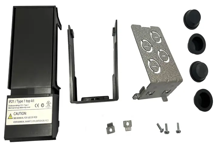
Items Supplied
The following parts are contained in the kit.
Table 2: Items Supplied in IP21/Type 1 Conversion Kits
| Item | Quantity |
| Top cover | 1 |
| Metal plate | 1 |
| Rubber grommet | 4–5 (depends on enclosure size) |
| Bottom cover | 1 |
| U-terminal | 2–3 (depends on enclosure size) |
| M4x10 screw | 3–4 (depends on enclosure size) |
Safety Information
Only qualified personnel are allowed to install the IP21/Type 1 conversion kit described in this installation guide. For important information about safety precautions for installation, refer to the drive’s operating guide.
WARNING
DISCHARGE TIME
The drive contains DC-link capacitors, which can remain charged even when the drive is not powered. High voltage can be present even when the warning indicator lights are off.
- Stop the motor, disconnect AC mains and permanent magnet type motors, and remove DC-link supplies, including battery back-ups, UPS, and DC-link connections to other drives.
- Wait for the capacitors to discharge fully and measure it before performing any service or repair work.
- The minimum waiting time is 4 minutes for MA01c, MA02c, MA01a, MA02a, and MA03a drives.
Installation
Mounting the IP21/Type 1 Conversion Kit
Procedure
- Fit top cover on the drive, see Illustration 1.

- Illustration 1: Fitting Top Cover
- Mount U-terminals on the metal plate and tighten screws, see Illustration 2. Maximum tightening torque: 2 Nm (17.7 in-lb).
- Remove knockouts on the metal plate and fit rubber grommets, see Illustration 2.

- Illustration 2: Mounting U-terminals and Fitting Rubber Grommets
- Mount metal plate on the drive and tighten screws, see Illustration 3. Maximum tightening torque: 2 Nm (17.7 in-lb).
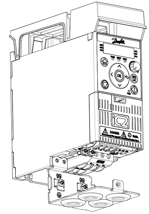
- Illustration 3: Mounting Metal Plate
- Fit bottom cover on the drive and tighten screw, see Illustration 4. Maximum tightening torque: 1.5 Nm (13.3 in-lb).
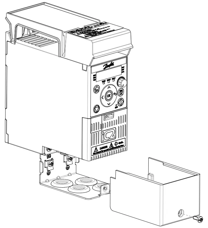
- Illustration 4: Fitting Bottom Cover
MORE INFORMATION
- Danfoss A/S
- Ulsnaes 1
- DK-6300 Graasten
- drives.danfoss.com
Danfoss can accept no responsibility for possible errors in catalogs, brochures, and other printed material. Danfoss reserves the right to alter its products without notice. This also applies to products already on order, provided that such alterations can be made without subsequent changes being necessary in specifications already agreed. All trademarks in this material are the property of the respective companies. Danfoss and the Danfoss logotype are trademarks of Danfoss A/S. All rights reserved.
FAQs
- Q: Can non-qualified individuals install the conversion kit?
- A: No, only qualified personnel should carry out the installation due to safety concerns related to high-voltage components.
Documents / Resources
 |
Danfoss IP21 Type 1 Conversion Kit [pdf] Installation Guide MA01c, MA02c, MA01a, MA02a, MA03a, IP21 Type 1 Conversion Kit, IP21, Type 1 Conversion Kit, 1 Conversion Kit, Conversion Kit |