![]() ENGINEERING TOMORROW
ENGINEERING TOMORROW
User Guide
Vickers by Danfoss
PVM Variable Displacement Piston Pump
Design Code B
Up to 315 bar
73.7/81 cc/rev
(4.5 – 4.94 ins/rev)
Variable Speed Drive Ready
Introduction
Vickers by Danfoss M Series pumps are open circuit, axial piston designs. A variety of control options allows the pumps to perform most efficiently in a specific application. Efficiency of the pump controls allows down-sizing of system cooling needs, saving up front cost in the machine. Alternatively, cooling capacity could be kept the same and the flow capability of the system increased, thus improving performance and customer satisfaction.
The M Series also contains a strong proven rotating group allowing the pumps to handle pressures up to 315 bar(4568 psi) continuous with less maintenance cost . High-load carrying capacity bearings and a stiff drive shaft help provide very long life at rated industrial condit ions, reducing operating costs and extending operating life.
M Series pumps feature a saddle-type yoke with steel-backed polymer bearings. The stiff yoke reduces deflection and allows even loading of bearings, improving life. A single control piston reduces loading on the yoke, resulting in reduced pump size which allows installation in tighter locations.
M Series pumps operate at a level of quietness that exceeds the requirements of today’s demanding work conditions. The pumps feature a unique three-piece envelope (flange, housing and valve block) specifically created for low fluid-borne and structure-borne noise levels. Another pump feature – a bimetal timing plate – improves pump filling characteristics which, in turn, reduce fluid-borne noise and extend pump life.
M Series pumps reduce, or in some cases remove, the need for damping barriers between the noise source and the operator. This saves money on the installed cost of the system while improving customer comfort.
An adjustable maximum stop provides a means of tuning flow to your system, while gauge ports allow monitoring of inlet and outlet conditions. These standard features reduce system complexity and cost.
Mounting flange is offered in SAE configurations, and ports are offered in SAE flange versions.
Side ported models are available to facilitate plumbing and help fit the pump to your machine space needs.
Multiple drain ports allow many mounting orientations, reducing installed costs.  M Series pumps are capable of operating with many types of hydraulic fluids used in industrial systems.
High-water-content and phosphate ester fluids can be accommodated, in addition to the typical petroleum based and synthetic fluids.
Typical Applications
- Mining machinery
- Injection molding machines
- Metal forming machines
- Oil and Gas Equipment
- Conveyor lines
- Primary metals
- Metal cutting equipment
Features and Benefits
- Tear drop shaped housing contains fluid borne sound and reduces operator fatigue
- Standard adjustable maximum volume screw and gage ports give the ultimate flexibility to the engineer or service technician
- High overall efficiency reduces operating costs
- Robust shaft bearings extends operating life and lowers maintenance costs
- Multiple port types and locations aid in flexibility of machine design
- Very low pressure ripple reduces shock in the system resulting in less leakage
Model Code Selection

![]() Product Series
Product Series
PVM – M Series Variable Piston Pump
![]() Displacement
Displacement
074 73.7 cm3/r [8.00 in3/r] (315 bar max.)
081 81 cm3/r [8.60 in3/r] (230 bar max.)
![]() Valve Plate
Valve Plate
E – Industrial -1800 rpm max
M – Mobile – Higher speed version.
![]() Input Rotation
Input Rotation
R – Clockwise (Right hand)
L – Counter-clockwise (Left hand)
![]() Input Shaft
Input Shaft
09 – SAE J744-32-1 SAE C Straight Keyed
10 – SAE J744-38-1 SAE C-C Straight Keyed
11 – SAE J744-32-4 SAE C 14T Spline
12 – SAE J744-38-4SAE “CC” (17T)Spline
![]() Mounting Flange
Mounting Flange
G – SAE J744-127-4 C 4-Bolt
![]() Main Port Location
Main Port Location
S – Side Ported
![]() Main Port Type
Main Port Type
2 – SAE J518 Flange Ports SAE Auxiliary Ports
![]() Control
Control
0 – None
A – Pressure Compensator
B – Pressure and Flow Compensator with Bleed Down Orifice
C – Pressure and Flow Compensator with Plugged Orifice
E – Industrial Control (Pressure and flow compensated)
F -Industrial Control (Pressure compensated)
L – Power Control/Torque Limiter
![]() Pressure Compensator Setting
Pressure Compensator Setting
000 – None
070 – 070±4 bar [1015±58 lbf/ in2] [Default]
230 – 230±4 bar [3335±58 lbf/ in2] [Default for 081 cc/r]
315 – 315 bar [4567 lbf/in2] [Default for 074cc/r]
![]() Flow Compensator Setting
Flow Compensator Setting
00 – None
11 – 11 bar setting
20 – 20 bar setting
![]() Power control
Power control
Torque Limiter Setting
000 – None
050 – Limited to 50 kW*
(Adjustable From 20-90 % Of Rated Torque, * For Any Other Values Specify Power in kW, Available in Increments Of 5 kW)
![]() Auxiliary Mounting Pad
Auxiliary Mounting Pad
0 – None (Non-Through Drive)
1 – Auxiliary SAE A-Mount with Cover Plate and No Coupler
A – SAE A 2-Bolt 9T Spline
B – SAE A 2-Bolt 11T Spline
C – SAE B 2-/4-Bolt 13T Spline
D – SAE B-B 2-/4-Bolt 15T Spline
E – SAE C 2-/4-Bolt 14T Spline
F – SAE C-C 2-/4-Bolt 17T Spline
![]() Paint
Paint
0 – No paint
A – Standard black paint
![]() Design Code
Design Code
B – B
![]() Differentiator
Differentiator
– –
![]() Pump Special Features
Pump Special Features
00 – Adjustable Max Displacement Stop
![]() Compensator Special Features
Compensator Special Features
0 – None
(Contact Danfoss for options)
![]() Customer Identification
Customer Identification
0 – None
(Contact Danfoss for options)
Specifications and Performance
Quiet version, optimized for 1000-1800 rpm (E)
Displacement, Pressure and Flow Ratings At 50°C (120°F), SAE 10W oil, 1 bar absolute (0 psig) inlet
| Geometric | Maximum Pressure bar (psi) | Maximum Flow at 315 bar (4500 psi) | |||||
| Model Series | Displacement cm3/r (in3 /r) |
Nominal Peak** | @1800 r/min | @1500 r/min | @1200 r/min | @1000 r/min | |
| PVM074 | 73.7 (4.5 ) | 315 (4568) | 350 (5000) | 127 (33.5 ) | 106 (28) | 86 (22.7 ) | 70 (18.5) |
| PVM081 | 81 (4.94 ) | 230 (3300) | 280 (4000) | 139 (37) | 116 (31) | 93 (25) | 76 (20) |
**Less than 0.5 second.
Speed, Input Power and Torque Ratings At 50°C (120°F), SAE 10W oil, 1 bar absolute (0 psig) inlet
| Maximum | OperatingMaximum Input Power at 280 bar (4000 psi) kw (hp)*@88% M.E. | Max torque at 280 bar (4000psi) | |||||
| Model Series | Speed r/min | @1800r/min | @1500 r/min | @1200r/min | @1000r/min | Nm (lb-ft)r/min | kg (lb) |
| PVM074 | 1800 | 63 (84) | 52 (70) | 42 (56) | 35 (47) | 334 (246 ) | 45(99) |
| PVM081 | 1800 | 56 (75) | 46 (62) | 35 (47) | 28 (37) | 286 (211) | 45(99) |
Standard Response Times*
| Model Series | On Stroke (msec) | Off Stroke (msec) |
| PVM074 | 85 | 30 |
| PVM081 | 85 | 30 |
*Values with pressure compensator control.
High speed version (M)
Displacement, Pressure and Flow Ratings At 93°C (200°F), SAE 10W oil, 1 bar absolute (0 psig) inlet
| Geometric | Maximum Pressure bar (psi) | Maximum Flow at 315 bar (4500 psi) | ||
| Model Series | Displacement cm3/r (in3 /r) | Nominal Peak** | Flange Ports l/min (USgpm) @ 1 bar inlet |
|
| PVM074 | 73.7 (4.5 ) | 315 (4568) | 350 (5000) | 163 (43) @ 2400 r/min |
| PVM081 | 81 (4.94 ) | 230 (3300) | 280 (4000) | 181 (48) @ 2400 r/min |
**Less than 0.5 second.
Speed, Input Power and Torque Ratings At 93°C (200°F), SAE 10W oil, 1 bar absolute (0 psig) inlet
| Approximate | Operating Speed and Pressure r/min | Max. Input Power at | Max. Torque at | ||
| Model Series | 1 bar Inlet | 0,85 bar Inlet | Max. Speed and 280 bar (4000 psi) kW (hp) | 280 bar (4000 psi) Nm (lb-ft) |
Weight (dry) kg (lbs) |
| Flange Ports | Flange Ports | ||||
| PVM074 | 2400 r/min | 84 (113 ) | 334 (246 ) | 45 (99) | |
| 1900r/min | 69 (93) | ||||
| PVM081 | 2400 r/min | 69 (93) | 276 (204 ) | 45 (99) | |
| 1900r/min | 55 (74) | ||||
Standard Response Times*
| Model Series | On Stroke (msec) | Off Stroke (msec) |
| PVM074 | 95 | 30 |
| PVM081 | 135 | 30 |
*Values with pressure compensator control.
Variable Speed Drive
Variable Speed Performance- System Pressure vs Speed
| Model Series | Max Speed “E”* (rpm) | Max Speed “M”*(rpm) | Min Speed (rpm) | Nominal Pressure (bar) | Peak Pressure (bar) ** | Inertia (kg-cm2) |
| PVM074 | 1800 | 2400 | 0 | 315 | 350 | 78.1 |
| PVM081 | 1800 | 2400 | 0 | 230 | 280 | 72.7 |
* Valve plate type
**Less than 0.5 second.
Note – For Variable Speed Drive applications, Modelcode Position 14 should be set at 0 and position 15, 16, 17 should be set to 000 to configure pump to “Fixed Displacement” type.
Moment of Inertia (single pump rotating group
| Model | Moment of Inertia | |
| N-m (sec2) | lbf-in (sec²) | |
| PVM074 | 0.0078 | 0.0691 |
| PVM081 | 0.0073 | 0.0643 |
PVM System Pressure vs. Shaft Speed  Test condition: Mineral oil SAE 10W, oil temperature 49º C (120º F), 1 bar absolute inlet pressure.
Control Options
Pressure Compensator Control – Code A
The pump will provide a cotinuously modulated flow to meet changing load demands at a pre-adjusted compensator pressure. At pressures below the compensator setting, the pump will operate at maximum displacement.
![]() Warning: The pressure compensator may be adjusted beyond the rated pressure of the pump. When adjusting the pressure limiter, install a 0-350 bar (0-5000 psi) gage in the outlet gage port and limit the pressure setting to the continuous rated pressure for the pump displacement
Warning: The pressure compensator may be adjusted beyond the rated pressure of the pump. When adjusting the pressure limiter, install a 0-350 bar (0-5000 psi) gage in the outlet gage port and limit the pressure setting to the continuous rated pressure for the pump displacement  Pressure Cut-off
Characteristics of Pressure
Compensator Control
Industrial: at 50°C (120°F), Static conditions
Mobile: 93°C (200 °F), Static conditions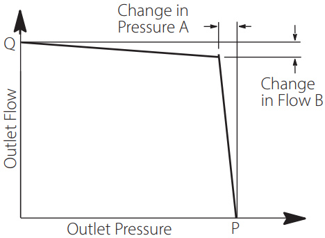
Pressure Cut-off Characteristics of Pressure Compensator Control @ 50°C (120°F), Static Conditions
| “P” Outlet | |||||
| Model Series | Max. Speed r/min | “Q” Outlet Flow Pressure l/ min (USgpm) bar (psi) |
A bar (psi) |
B L/min (USgpm) |
|
| PVM074 | 1800 | 127 (33.5) | 315 (4568) | 1,5 (22) | 37 (9,8) |
| PVM081 | 1800 | 141 (37) | 230 (3300) | 1,5 (22) | 37(9,8) |
Pressure Cut-off Characteristics of Pressure Compensator Control @ 93°C (200°F), Static Conditions
| “P” Outlet | |||||
| Model Series | Rated Speed r/min | “Q” Outlet Flow Pressure l/ min (USgpm) bar (psi) |
A bar (psi) |
B L/min (USgpm) |
|
| PVM074 | 2400 | 174 (46) | 315 (4568) | 1,5 (22) | 33 (9,8) |
| PVM081 | 2400 | 185(49) | 230 (3300) | 1,5 (22) | 33(9.8) |
Load Sensing and Pressure Compensator Control – Code B or C
The pump will provide power matching of pump output to system load demand, maximizing efficiency and improving load metering characteristics of any directional control valve installed between the pump and the load.
Load sensing ensures that the pump always provides only the amount of flow needed by the load. At the same time, the pump operating pressure adjusts to the actual load pressure plus a pressure differential required for the control action. When the system is not demanding power, the load sense control will operate in an energy-saving stand-by mode.
Typically, the differential pressure is that between the pressure inlet and service port of a proportionally controlled directional valve, or a load sensing directional control valve.
If the load pressure exceeds the system pressure setting, the pressure compensator de-strokes the pump. The load sensing line must be as short as possible and can also be used for remote control or unloading of the pump pressure. For remote control purposes, it is recommended that you contact your Danfoss representative for the correct configuration of the control.
![]() Warning: The pressure compensator may be adjusted beyond the rated pressure of the pump. When adjusting the pressure limiter, install a 0-350 bar (0-5000 psi) gage in the outlet gage port and limit the pressure setting to the continuous rated pressure for the pump displacement..
Warning: The pressure compensator may be adjusted beyond the rated pressure of the pump. When adjusting the pressure limiter, install a 0-350 bar (0-5000 psi) gage in the outlet gage port and limit the pressure setting to the continuous rated pressure for the pump displacement.. Industrial Control Compensator – Code E and F
This pump is intended for use when multiple, remote, or electronically controlled compensating settings, with or without load sensing, are desired.
Pressure compensation is obtained when an internal plug is removed, the load-sense signal port is kept plugged, and internal pilot pressure is applied to the spring chamber of the control spool. For pressure compensation with load sensing, the internal plug stays, the load- sense signal port is unplugged, and pilot pressure is externally applied.
An external relief valve (not supplied) controls spring chamber pressure. The externally adjustable spring determines the differential pressure setting of the control. Outlet pressure is limited to the valve of the spring chamber (pressure port) pressure, plus control differential pressure.
Spring chamber (pilot) pressure is separated from outlet pressure by an internal orifice.
Outlet pressure shifts the spool when pressure drop across the orifice reaches the differential pressure setting, and the pump de-strokes.
The relief valve can be mounted to an NFPA-D03/ISO 4401-03 pad on the pump control, or remotely located via tapping and blanking plates installed on the pad.
The standard factory-set differential pressure setting of the pump control is 20 bar (290 psi) and is not specified in the pump model number. Any other ordered differential pressure, within the control’s adjustable pressure range of 17-35 bar (247- 508 psi), will be specified in the model number.
With Pressure & Flow Compensator (E) Pressure Compensating without Load Sensing (F)
Power Control – Code L
The Power control limits the maximum torque output by the piston pump by reducing the displacement as pressure increases hence limiting the power rating at a given speed.
As pressure increases the pump displacement is reduced such that the set torque value is not exceeded.
The torque can be set between 20-90% of rated torque for given displacement at 1500 rpm.
![]() Warning: The pressure compensator may be adjusted beyond the rated pressure of the pump.When adjusting the pressure limiter, install a 0-350 bar (0-5000 psi) gage in the outlet gage port and limit the pressure setting to the continuous rated pressure for the pump displacement.
Warning: The pressure compensator may be adjusted beyond the rated pressure of the pump.When adjusting the pressure limiter, install a 0-350 bar (0-5000 psi) gage in the outlet gage port and limit the pressure setting to the continuous rated pressure for the pump displacement.
Note:
If the application runs at a different speed, for example 1800 rpm, and the power should be limited to 50 kW then use this formula: (50 kW)/(1800 rpm)×1500 rpm=41.66 kW
Then round off to the next available modelcode i.e., 045.
 Characteristics of Code L Power Control at 50°C (120°F), static conditions.
Torque setting range by displacemnent
| Displacement (cc) | Rated Torque lb-in (N-m) |
Min torque setting lb-in (N-m), 20% of rated torque* |
Max torque setting lb-in (N-m), 90% of rated torque |
| PVM074 | 2920 (330) | 584 (66) | 2628 (297) |
| PVM081 | 2626 (297) | 525 (59) | 2363 (267) |
* for Minimum torque setting (20%) the pump may not deliver the flow at higher pressure. Please contact Danfoss Engineering for flow generated at max pressure
Operation and installation – Power Control / Torque Limiter
Description
PVM series piston pump with Power Control consists of, A) pump with modified pressure and flow compensator and B) Power Control subassembly installed.
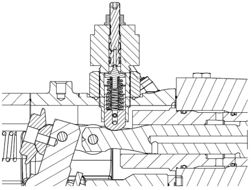
Power Control Operation
The Power Control Subassembly consists of a poppet type valve guided by a specially designed control piston with a unique profile.
The pressure setting of the poppet valve, being guided by the profile on the control piston, is dependent on the actual displacement of the pump. For lower displacement the pressure setting is high. As displacement is increased, the pressure setting is reduced according to the profile on the control piston. The poppet type valve gets pressure signal either from the modified load sense port (for Pressure Flow Compensated) or the pump outlet pressure (for Pressure Compensated). The power control subassembly regulates this pressure based on the displacement. This regulated pressure is internally fed back to the control piston chamber, which compensates by adjusting the pump displacement appropriately.
This results in achieving the desired control of constant input power.
Power Control Adjustment
To adjust the control power setting, power measurement devices are required. For Input power, motor torque and speed need to be measured, typically achieved by use of a clamp style ammeter. For output power, devices for pump pressure and flow measurements are required, such as pressure gages or transducers, and flow meters.
The pump comes with factory set power setting. The setting can be changed by loosening the lock nut on top of the control subassembly and turning the adjust ment screw with help of a hex key. Rotating adjustment screw clockwise increases the power setting while rotating it anti-clockwise reduces it. After adjustment as required ensure that the locknut is tightened properly.
Performance
Quiet version, optimized for 1000-1800 rpm (E) PVM074
Typical Noise Levels at 1800 and 1200 r/min with Petroleum Oil (10W) at 50°C (120°F) and 1.0 bar absolute (0 psi gauge) Inlet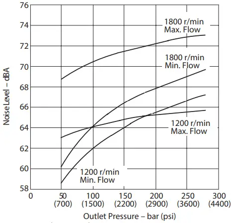 Sound pressure data equivalent toNFPA.
Delivery and Efficiency at 1800 r/min 50°C (120°F) and 1.0 bar absolute (0 psi gauge) Inlet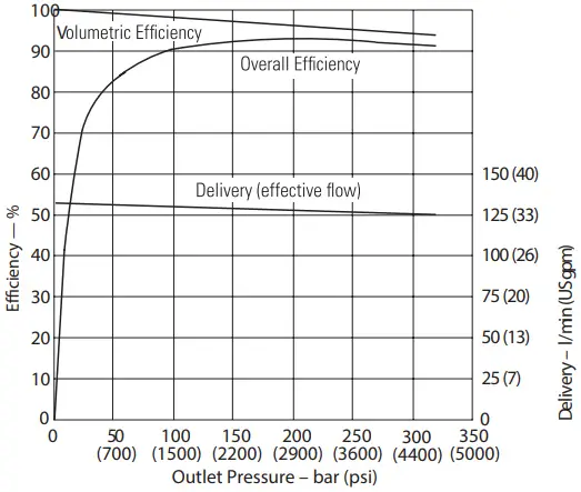
Typical Noise Levels at 150 0 and 1000 r/min with Petroleum Oil (10W) at 50°C (120°F) and 1.0 bar absolute (0 psi gauge) Inlet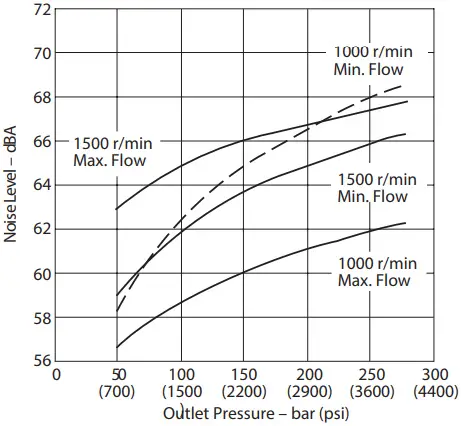
Input Torque and Power at 1800 r/min 50°C (120°F) and 1.0 bar absolute (0 psi gauge) Inlet
Delivery and Efficiency at 1500 r/min 50°C (120°F) and 1.0 bar absolute (0 psi gauge) Inlet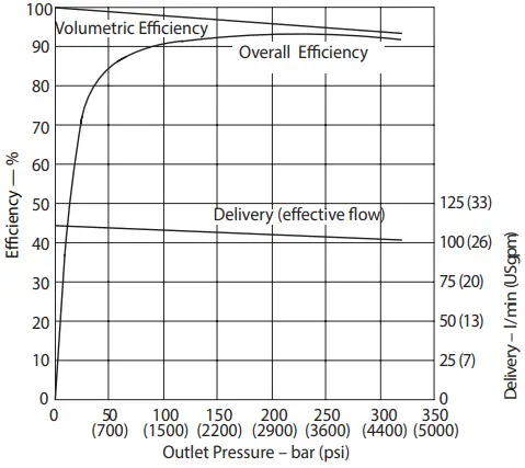
Delivery and Efficiency at 1200 r/min 50°C (120°F) and 1.0 bar absolute (0 psi gauge) Inlet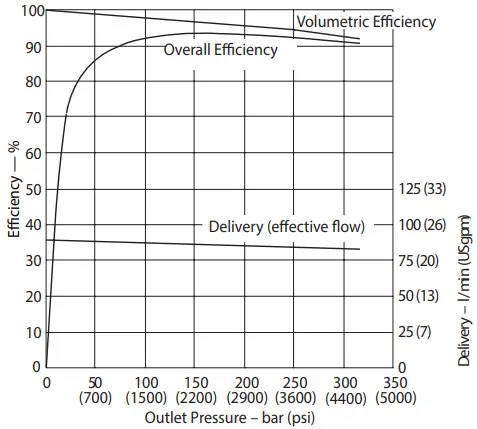
Input Torque and Power at 1500 r/min 50°C (120°F) and 1.0 bar absolute (0 psi gauge) Inlet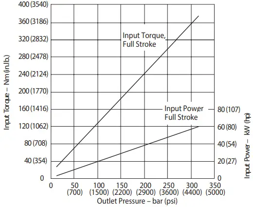
Input Torque and Power at 1200 r/min 50°C (120°F) and 1.0 bar absolute (0 psi gauge) Inlet
Delivery and Efficiency at 1000 r/min 50°C (120°F) and 1.0 bar absolute (0 psi gauge) Inlet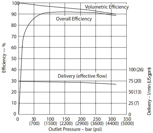 Case Flow Versus Outlet Pressure at Full Flow, 1800 r/min 50°C (120° F) and 1.0 bar absolute (0 psi gauge) Inlet
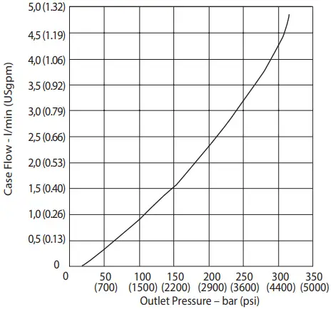
Input Torque and Power at 1000 r/min 50°C (120°F) and 1.0 bar absolute (0 psi gauge) Inlet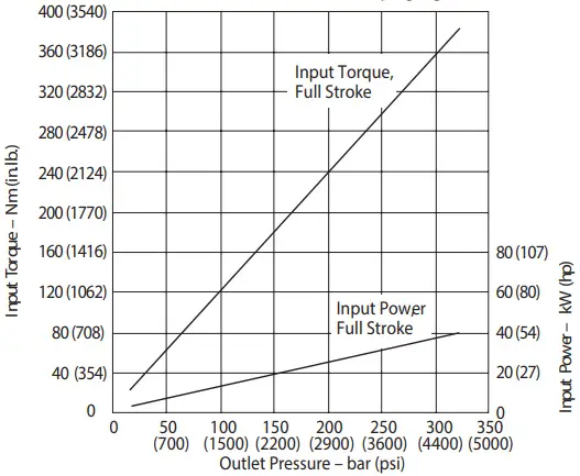
Case Flow Versus Outlet Pressure at Cutoff, 1800 r/min 50°C (120° F) and 1.0 bar absolute (0 psi gauge) Inlet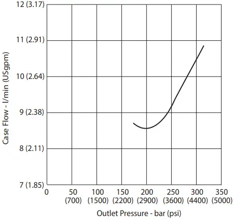
Higher speed version (M) PVM074
Typical Noise Levels Petroleum Oil (10W) at 93°C (200°F), 1.0 bar absolute (0 psi gauge) Inlet (Sound pressure data equivalent to NFPA.
Delivery and Case Flow Versus Speed @ 93°C (200°F) and 1.0 bar absolute (0 psi gauge) inlet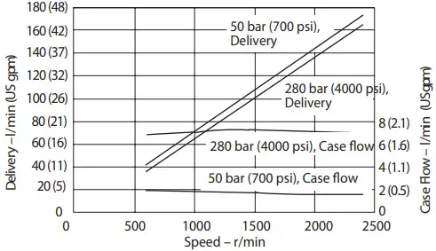
Input Torque Versus Speed @ 93°C (200°F) and 1.0 bar absolute (0 psi gauge) inlet
Ov erall Efficiency Versus Speed at 93°C (200°F) and 1.0 bar absolute (0 psi gauge) Inlet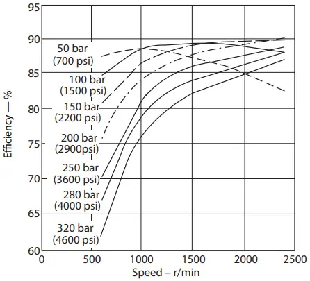
Input Power Versus Speed 93°C (200°F), 1.0 bar absolute (0 psi gauge) Inlet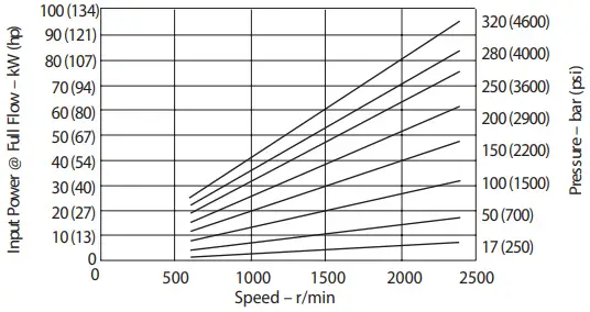
Input Torque and Case Flow Versus Speed @ 93°C (200°F), load sense standby and 1.0 bar absolute (0 psi gauge) inlet
Input Torque and Case Flow Versus Speed @ 93°C (200°F), cut-off and 1.0 bar absolute (0 psi gauge) inlet
Quiet version, optimized for 1000-1800 rpm (E) PVM081
Typical Noise Levels at 1800 and 1200 r/min. with Petroleum Oil (10W) at 50°C (120°F) and 1.0 bar absolute (0 psi gauge) Inlet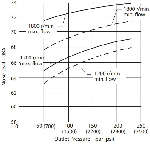
Delivery and Efficiency at 1800 r/min, 50C (120F), and 1.0 bar absolute (0 psi gauge) Inlet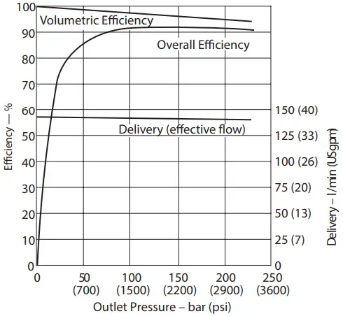 Typical Noise Levels at 1500 and 1000 r/min. with Petroleum Oil (10W) at 50°C (120°F) and 1 .0 bar absolute (0 psi gauge) Inlet
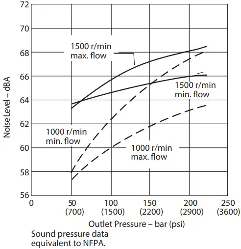
Input Torque and Power at 1800 r/min, 50C (120F), and 1.0 bar absolute (0 psi gauge) Inlet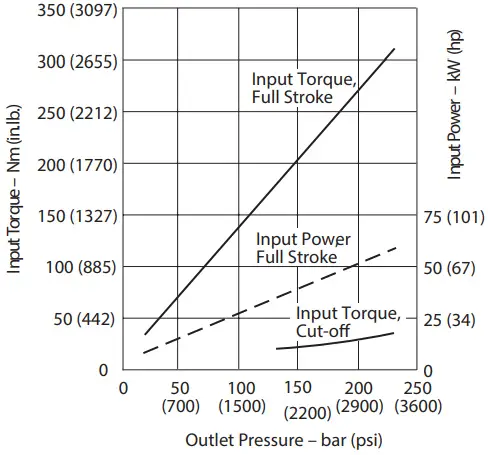
Delivery and Efficiency at 1500 r/min, 50C (120F), and 1.0 bar absolute (0 psi gauge) Inlet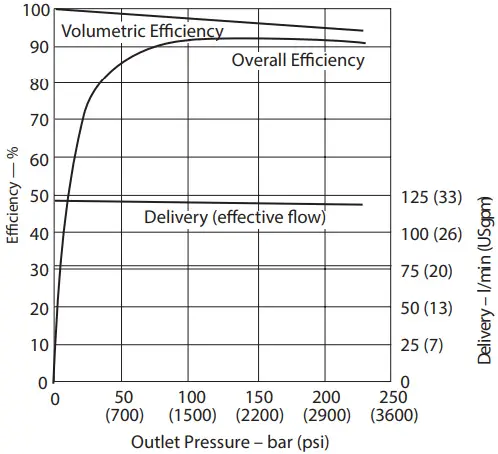
Delivery and Efficiency at 1200 r/min, 50C (120F), and 1.0 bar absolute (0 psi gauge) Inlet
Input Torque and Power at 1500 r/min, 50C (120F), and 1.0 bar absolute (0 psi gauge) Inlet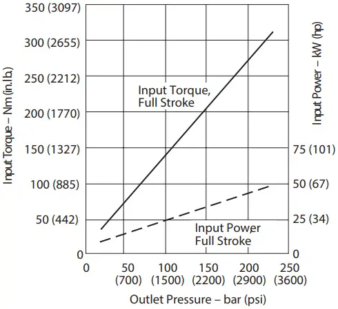
Input Torque and Power at 1200 r/min, 50C (120F), and 1.0 bar absolute (0 psi gauge) Inlet
Delivery and Efficiency at 1500 r/min, 50C (120F), and 1.0 bar absolute (0 psi gauge) Inlet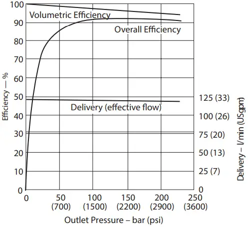
Delivery and Efficiency at 1200 r/min, 50C (120F), and 1.0 bar absolute (0 psi gauge) Inlet
Input Torque and Power at 1500 r/min, 50C (120F), and 1.0 bar absolute (0 psi gauge) Inlet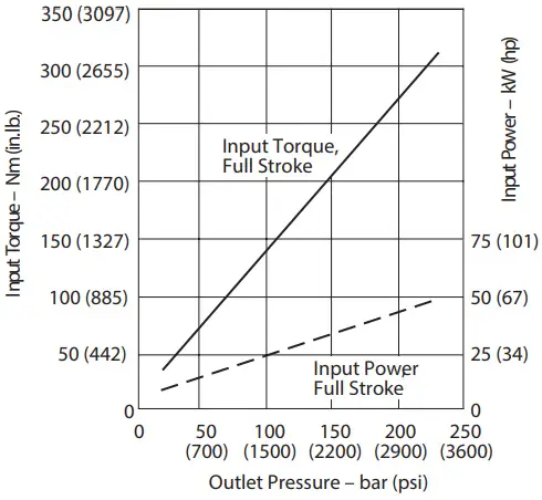
Input Torque and Power at 1200 r/min, 50C (120F), and 1.0 bar absolute (0 psi gauge) Inlet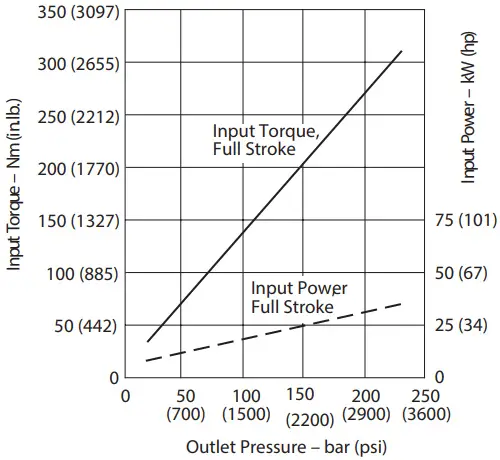
Higher speed version (M) PVM081
Typical Noise Levels at 2400 & 600 r/min with Petroleum Oil (10W) at 93°C (200°F) and 1.0 bar absolute (0 psi gauge) Inlet
Overall Efficiency versus Speed at 93°C (200°F) and 1.0 bar absolute (0 psi gauge) inlet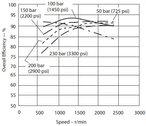
Delivery and Case Flow versus Speed at 93°C (200°F), Full Flow 1.0 bar absolute (0 psi gauge) Inlet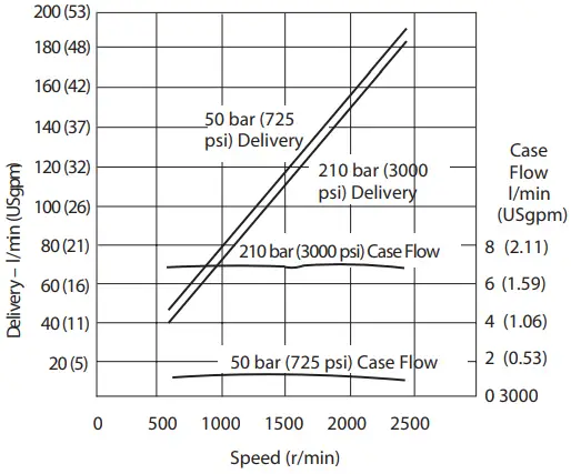
Input Torque versus Speed at 93°C (200°F), Full Flow and 1.0 bar absolute (0 psi gauge) Inlet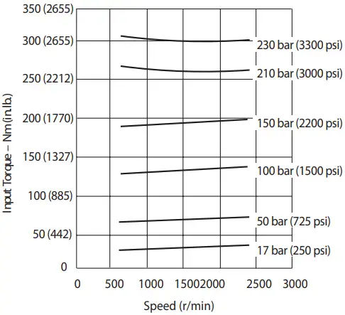
Input Power versus Speed at 93°C (200°F), Full Flow and 1.0 bar absolute (0 psi gauge) Inlet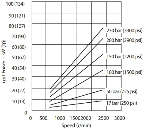
Input Torque and Case Flow versus Speed at 93°C (20 0°F), Load Sense Standby and 1.0 bar absolute (0 psi gauge) Inlet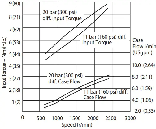
Input Torque and Case Flow versus Speed at 93°C (20 0°F), Pressure Limit Cut-off and 1.0 bar absolute (0 psi gauge) Inlet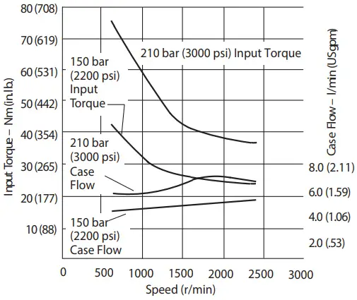
Side-ported Models
Without through-drive capability
PVM 074/081*Right-hand only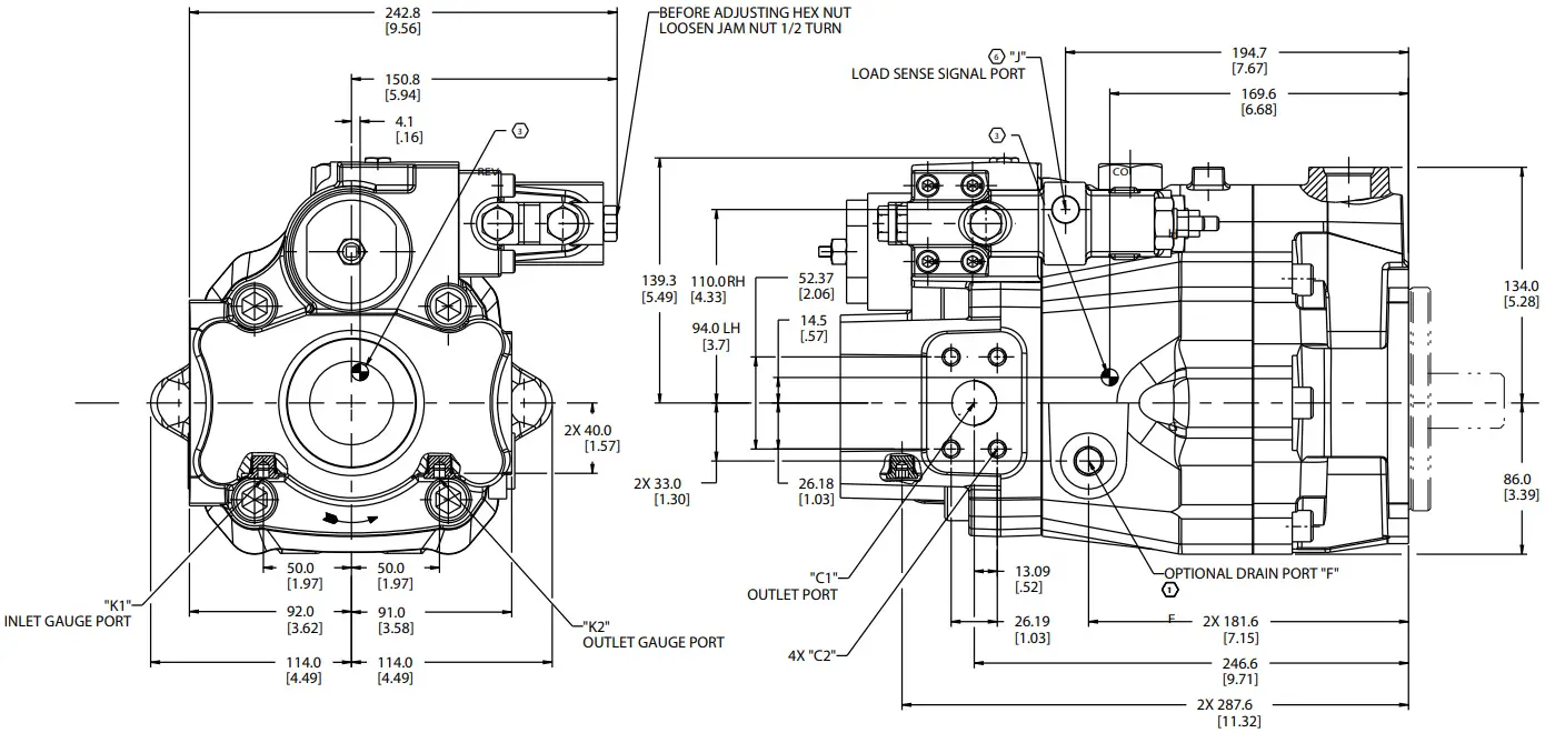 RIGHT HAND ROTATION SHOWN WITH PRESSURE COMPENSATOR WITH LOAD SENSE
| FLANGE PORTS | PORT | “B1” | “B2” | “C1” | “C2” | “F” | “J” | “K1” | “K2” |
| SAE PORT | 2.0 INLET PORT “B1” SAE J518C 4 BOLT FLANGE STANDARD PRESSURE SERIES | .500-13 UNC-2B THREAD 1.06 MINIMUM |
1.0 OUTLET PORT “C1” SAE J518C, 4 BOLT FLANGE STANDARD PRESSURE SERIES | .375-16 UNC-2B THREAD .88 MINIMUM | SAE J514 O-RING BOSS PORT “F” FOR .75 O.D. TUBE 1.0625-12 UN-2B THREAD | SAE J514 O-RING BOSS PORT “J” FOR .375 O.D. TUBE .562-18 UNF-2B THREAD | SAE J514 O-RING BOSS PORT “K1” FOR .375 O.D. TUBE .562-18 UNF-2B THREAD | SAE J514 O-RING BOSS PORT “K2” FOR .375 O.D. TUBE .562-18 UNF-2B THREAD |

With through-drive capability
PVM 074/081
RIGHT HAND ROTATION SHOWN WITH PRESSURE COMPENSATOR WITH LOAD SENSE LEFT HAND ROTATION SHOWN ON SHEET 2
| PORT | “B1” | “B2” | “C1” | “C2” | “F” | “J” | “K1” | “K2” |
| SAE PORT | 2.0 INLET PORT “B1” SAE J518C 4 BOLT FLANGE STANDARD PRESSURE SERIES | .500-13 UNC-2B THREAD 1.06 MINIMUM | 1.0 OUTLET PORT “C1” SAE J518C, 4 BOLT FLANGE STANDARD PRESSURE SERIES | .375-16 UNC-2B THREAD .88 MINIMUM | SAE J514 O-RING BOSS PORT “F” FOR .75 O.D. TUBE 1.0625-12 UN-2B THREAD | SAE J514 O-RING BOSS PORT “J” FOR .375 O.D. TUBE .562-18 UNF-2B THREAD | SAE J514 O-RING BOSS PORT “K1” FOR .375 O.D. TUBE .562-18 UNF-2B THREAD | SAE J514 O-RING BOSS PORT “K2” FOR .375 O.D. TUBE .562-18 UNF-2B THREAD |

Thru-drive Models
PVM074/081 *Right-hand only
Generic through-drive assembly
| MODEL CODE POSITION 23 | Item No. 69 (Adapter) (QTY 1) | Item No.70 (Screw) (QTY 4) | Item No.71 (O-ring) (QTY 1) | Item No.72 (O-ring) (QTY 1) | Item No.73 (Coupler) (QTY 1) |
| A | ○ | ○ | ○ | ● | ● |
| B | ○ | ○ | ○ | ● | ● |
| C | ● | ● | ● | ● | ● |
| D | ● | ● | ● | ● | ● |
| E | ● | ● | ● | ● | ● |
| F | ● | ● | ● | ● | ● |
○ = Not required for through-drive
● = Required for through-drive
| Model Code Position 23 | |
| Description | |
| A | For SAE”A” pad with a 9T, 16/32 DP, 30°Pressure angle, Involute spline |
| B | For SAE”A” pad with a 11T, 16/32 DP, 30°Pressure angle, Involute spline |
| C | SAE “B” 13T, 16/32 DP, 30° Pressure angle, Involute spline |
| D | SAE “B-B” 15T, 16/32 DP, 30°Pressure angle, Involute spline |
| E | SAE “C” 14T, 12/24 DP, 30° Pressure angle, Involute spline |
| F | SAE “C-C” 17T, 12/24 DP, 30° Pressure angle, Involute spline |
PVM074/081 *Right-hand only
SAE”A” 2 Bolt Adaptor Flange
 Without adapter plate
| Model Code Position 23 | Coupling | Length mm (inch) |
| A | SAE “A,” 9T | 64.5 (2.54) |
| B | SAE “A,” 11T | 65.3 (2.57) |

 Right hand rotation Shown with Pressure Compensator with Load Sense
PVM074/081 *Right-hand only
SAE”B” 2-/4- Bolt Adaptor Flange
 With adapter plate
| Model Code Position 23 | Coupling | Length mm (inch) |
| C | SAE “B,” 13T | 95.3 (3.75) |
| D | SAE “B-B,” 15T | 95.3 (3.75) |
 View Rotated 90°
 Right hand rotation Shown with Pressure Compensator with Load Sense
PVM074/081 *Right-hand only
SAE”C” 2-/4- Bolt Adaptor Flange
 With adapter plate
| Model Code Position 23 | Coupling | Length mm (inch) |
| E | SAE “C,” 14T | 95.3 (3.75) |
| F | SAE “C-C,” 17T | 91.8 (3.61) |
 View Rotated 90°
 Right hand rotation
Shown with Pressure Compensator with Load Sense and SAE 2-/4-bolt “C” Adapter Flange
Mounting Flange Options
G – SAE J744-127-4 C 4-BOLT
Shaft Options
09 – SAE J744-32-1 SAE C STRAIGHT KEYED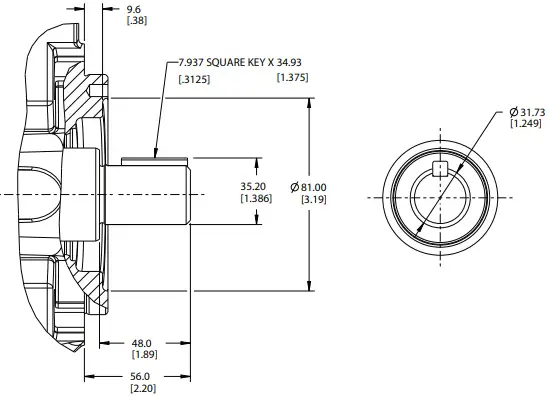
10 – SAE J744-38-1 SAE C-C STRAIGHT KEYED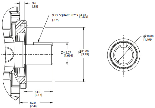
11 – SAE J744-32-4 SAE C 14T SPLINE
12 – SAE J744-38-4SAE “C-C” (17T)Spline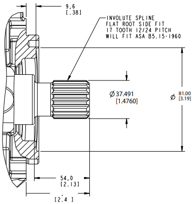
Input Shaft Selection Data
SAE Splined Shafts
| Model Series | Shaft Designation | Shaft Code | Max. Input Torque† Nm (lb. in.) |
Max. Thru-drive Output Torque‡ Nm (lb. in.) |
| PVM074/081 | SAE J744-32-4 (SAE “C,” 14T) | 11 | 640 (5660) | 515 (4560) |
| SAE J744-38-4 (SAE “C-C,” 17T) | 12 | 1215 (10,750) | 515 (4560) |
SAE Keyed Shafts
| Model Series | Shaft Designation | Shaft Code | Max. Input Torque† Nm (lb. in.) | Max. Thru-drive Output Torque‡ Nm (lb. in.) |
| PVM074/081 | SAE J744-32-1 (SAE “C”) |
09 | 450 (3980) | 450 (3980)* |
| SAE J744-38-1 (SAE “C-C”) |
10 | 765 (6770) | 515 (4560) |
†Maximum total torque of the thru-drive pump and the thru-driven pump(s).
‡Maximum torque that can be applied to the thru-driven pump(s).
*This value is limited by the maximum input torque.
Port Options
Inlet and Outlet Ports
| Model Series | Inlet/Outlet Port Option | Port Code | Inlet Port “B” | Outlet Port “C” |
| PVM074/081 | nch Flange | 2 | SAE J518 Code 61, standard pressure. 2.00 inch diameter, .500-13 x 1.19 bolt hole | SAE J518 Code 61, standard pressure. 1.00 inch diameter, .375 -16 x .88 bolt holes |
Drain, Load Sensing, and Gauge Ports
| Model Series | Inlet/Outlet Port Option | Port Code | Drain Port “F” | Load Sensing Port “J” | Gauge Port “K” |
| PVM074/081 | Inch Flange | 2 | SAE J514 O-ring, 1’’ O.D. tube. 1.0625 -12UN-2B thread |
SAE J514 O-ring, .375’’ O.D. tube. .562-18 UNF 2B thread |
SAE J514 O-ring, .375’’ O.D. tube. .5625-18 UNF 2B thread |
Operating Requirements
Inlet Pressure, Case Pressure, and Operating Temperature Requirements
| Inlet Pressure | Case Pressure | Operating Temperature | |||||
| Rated Absolute | Minimum bar, absolute | Maximum Gauge | Maximum Continuous | Maximum Intermittent | Peak | Rated | Maximum Intermittent |
| bar (psi) | (in. Hg) | bar (psi) | bar (psi) | bar (psi) | bar (psi) | °C (°F) | °C (°F) |
| 1,0 (14.5) | 0,85 (5) | 3,5 (50) | 0,5 (7) | 2 (30) | 3,5 (50) | 82 (180) | 104 (220) |
Hydraulic Fluids
| Fluid | Recommended Operating Viscosity Range cSt (SUS) | Maximum Viscosity at Startup cSt (SUS) | Minimum Viscosity @ Max. Intermittent Temperature of 104°C (220°F) cSt (SUS) |
| Use antiwear hydraulic oil, or automotive type crankcase oil (designations SC, SD, SE, or SF) per SAE J183 FEB80 | 16 to 40 (83 to 187) | 1000 (4550) | 10 (90) |
For more information, see Danfoss publication 579. For operation on other alternative or environmentally friendly fluids, please contact your Danfoss Representative.
Bearing life at 50o C (120o F), SAE 10W oil, 1 bar abs (0 psig) inlet pressure
| Model Series | Pressurerated bar (psi) | Speed rated rpm | Flow rated lpm (gpm) | Bearing life rated L10 hours |
| 074 | 315 (4568) | 1800 | 127 (33.5) | 7000 |
Bearing life can be modified for flow, speed and pressure using the formula:
Fluid Cleanliness
The M Series pumps are rated in anti-wear petroleum fluids with a contamination level of 20/18/13 (Danfoss) or ISO 18/13.
Operation in fluids with levels more contaminated than this is not recommended. Fluids other than petroleum, severe service cycles, or temperature extremes are cause for adjustment of these codes. Please contact your Danfoss Representative for specific duty cycle recom mendation.
Vickers by Danfoss M Series pumps, as with any variable displacement piston pumps, will operate with apparent satisfaction in fluids up to the rating specified here. Experience has shown, however, that pump and hydraulic system life is not optimized with high fluid contamination levels (high ISO cleanliness codes).
Proper fluid condition is essential for long and satisfac tory life of hydraulic components and systems. Hydraulic fluid must have the correct balance of cleanliness, materials, and additives for protection against wear of components, elevated viscosity and inclusion of air.
Essential information on the correct methods for treating hydraulic fluid is included in Danfoss publication 561 – “Danfoss Guide to Systemic Contamination Control” – Available from your local Danfoss distributor. In this publication, filtration and cleanliness levels for extending the life of axial piston pumps and other system components are listed. Included is an excellent discussion of the selection of products needed to control fluid condition.
Example: PVM131 operating at 1200 rpm, at 230 bar, and 200 lpm
From the chart, find that the rated life is 14000 L10 hours, the rated pressure is 315 bar, the rated flow is 215 lpm and the rated speed is 1800 rpm. Using the formula provided, the new bearing life expectation is calculated as follows: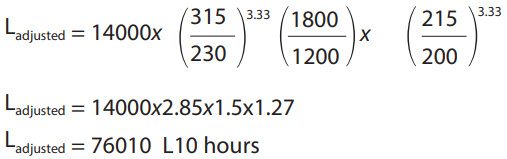 Further modification to bearing life are possible, including de-rating due to special fluids. Generally, standard water-glycol fluids reduce rated bearing life to 20% And case flushing is required. Please contact Danfoss engineering for assistance.
Moment of Inertia (single pump rotating group)
| Model | Moment of Inertia | |
| N-m (sec²) | lbf-in (sec²) | |
| PVM074 | 0.0078 | 0.0691 |
| PVM081 | 0.0073 | 0.0643 |
Alternate fluids guide
Specifications and Performance

Installation and Start-up
![]() Warning: Care should be taken that mechanical and hydraulic resonances are avoided in the application of the pump.
Warning: Care should be taken that mechanical and hydraulic resonances are avoided in the application of the pump.
Such resonances can seriously compromise the life and/or safe operation of the pump.
Drive Data
Mounting attitude can be either horizontal or vertical, using the appropriate case drain ports to ensure that the case remains full of fluid at all times. Consult your local Danfoss Representative if a different arrangement is required.
In those cases where geometric tolerances of mounting are critical, or where specific tolerance ranges are required and not specified, consult Danfoss Engineering for specific limits.
Direction of shaft rotation, viewed from the prime mover end, must be as indicated in the model designation on the pump– either right hand (clockwise) or left hand (counterclockwise).
Direct coaxial drive through a flexible coupling is recommended. If drives imposing radial shaft loads are considered, please consult your Danfoss Representative.
Start-up Procedure
Make sure the reservoir and circuit are clean and free of dirt/debris prior to filling with hydraulic fluid.
Fill the reservoir with filtered oil and fill to a level sufficient enough to prevent vortexing at the suction connection to pump inlet. It is good practice to clean the system by flushing and filtering, using an external slave pump.
Caution: Before the pump is started, fill the case through the uppermost drain port with hydraulic fluid of the type to be used. The case drain line must be connected directly to the reservoir and must terminate below the oil level.
Once the pump is started, it should prime within a few seconds. If the pump does not prime, check to make sure that there are no restrictions between the reservoir and the inlet to the pump, that the pump is being rotated in the proper direction, and that there are no air leaks in the inlet line and connections. Also check to make sure that trapped air can escape at the pump outlet.
After the pump is primed, tighten the loose outlet connections, then operate for five to ten minutes (unloaded) to remove all trapped air from the circuit.
If the reservoir has a sight gage, make sure the fluid is clear – not milky.
![]() Danfoss Power Solutions, Nordborgvej 81, 6430 Nordborg, Denmark, Tel. +45 74 88 22 22, Fax +45 74 65 25 80 danfoss.com/VickersIndustrial, E-mail: info@danfoss.com
Danfoss Power Solutions, Nordborgvej 81, 6430 Nordborg, Denmark, Tel. +45 74 88 22 22, Fax +45 74 65 25 80 danfoss.com/VickersIndustrial, E-mail: info@danfoss.com
Support E-mail: industrialpumpsmotorsupport@danfoss.com
Danfoss can accept no responsibility for possible errors in catalogues, brochures and other printed material. Danfoss reserves the right to alter its products without notice. This also applies to products already on order provided that such alterations can be made without subsequential changes being necessary in specifications already agreed. All trademarks in this material are property of the respective companies. Danfoss and the Danfoss logotype are trademarks of Danfoss A/S. All rights reserved.
![]() © 2023 Danfoss
© 2023 Danfoss
All Rights Reserved
Printed in USA
Document No. V-PUPI-TM007-E3
DAM No: BC481368704081en-000101
March 2024
Documents / Resources
 |
Danfoss Code B Variable Displacement Piston Pump [pdf] User Guide Code B Variable Displacement Piston Pump, Code B, Variable Displacement Piston Pump, Displacement Piston Pump, Piston Pump, Pump |


