Danfoss AK-CC 210B Controller For Temperature Control
Product Information
Specifications
- Model: AK-CC 210B
- Software Version: SW 1.0x
- Application: Plug-in cabinets in supermarkets
- Relays: 4 relays for Refrigeration, Defrost, Light, and user-selected application
Product Usage Instructions
- For ordering information, please consult the user manual.
- The controller can be connected to sensors and devices as per the instructions provided in the user manual.
- Data related to accuracy, sensor types, and applications is described in the manual.
Introduction
Application
- The AK-CC 210B is dedicated to “plug-in cabinets” in supermarkets.
Principle
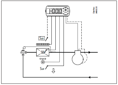
- The AK-CC 210B controls the temperature in the cabinet based on the measurement from a single sensor – Sair.
- This sensor can be placed in the cold airflow after the evaporator or in the warm airflow before the evaporator, depending on the construction and usage of the cabinet.
- A measurement of the defrost temperature can be obtained directly through the use of an S5 sensor or indirectly through the use of the Sair measurement.
- Relays: the first 3 relays are dedicated to Refrigeration, Defrost, and Light, respectively. The usage of relay 4 is selected by the application setting, and can be Alarm, Fan, Rail heat, Condenser fan or Compressor 2.
- The different applications are described
Advantages
- Many applications in the same unit
- The controller has integrated refrigeration-technical functions, so that it can replace a whole collection of thermostats and timers
- Buttons and a seal are embedded in the front
- Alarm monitoring of condenser temperature with compressor stop protection.
- Sealed relays for use with R290 refrigerants
- Can control two compressors
- Easy to remount data communication
- Quick set-up
- Two temperature references
- Digital inputs for various functions
- Clock function with super-cap backup
- Factory calibration that will guarantee better measuring accuracy than stated in the standard EN ISO 23953-2 without subsequent calibration (Pt 1000 ohm sensor)
Operation
Operation – Sensors
- One thermostat sensor – Sair – can be connected to the controller, and the relevant application defines the placement.
- It can be placed in the air before the evaporator or in the airflow after the evaporator. The latter is mainly used where there is a risk of too low a temperature at the products.
Defrost sensor
- The best signal concerning the evaporator’s temperature is obtained from a defrost sensor mounted directly on the evaporator.
- Here the signal may be used by the defrost function, so that the shortest and most energy-saving defrost can take place.
- If a defrost sensor is not required, defrost can be stopped based on time, or Sair can be selected.
Condenser temperature sensor
- A condenser temperature sensor – Sc – can be used for monitoring the temperature on the condenser.
- Depending on settings, alarms can be generated and other actions, including safety stop of compressor, can be initiated based on this temperature.
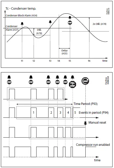
Condenser temperature alarms and actions
- An alarm warning can be activated when the temperature gets above a set Condenser Alarm limit and a critical alarm can be activated at a higher Condenser Block Alarm limit.
- At this critical level, different actions can be initiated e.g., turning off the light in the cabinet, turning off the compressor, or both. The wanted action is defined by the parameter “P92”.
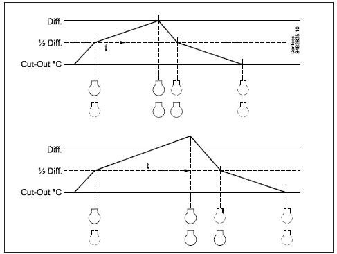
- Compressors can be permanently stopped if a defined number of critical alarms occur within a defined time period. If the number of events exceeds the setting in parameter “P94” within a period defined in “P93”, the last event will always include a compressor stop, together with other actions defined in “P92”.
- This state requires a manual reset before the compressor can start again.
Control of two compressors
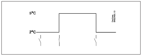
- This control is used for controlling two compressors of the same size. The principle for control is that one of the compressors connects at ½ the differential of the thermostat, and the other at the full differential. When the thermostat cuts in, the compressor with the fewest operating hours is started. The other compressor will only start after a set time delay, so that the load will be divided between them. The time delay has a higher priority than the temperature.
- When the air temperature has dropped by half the differential, one of the compressors will stop, while the other will continue working and not stop until the required temperature is achieved.
- The compressors used must be of a type that is capable of starting up against high pressure.
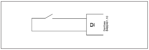
Change of temperature reference
- In an impulse appliance, for example, used for various product groups the temperature reference is changed easily with a contact signal on a digital input.
- The signal changes the normal thermostat setpoint by a predefined value. At the same time, the high and low alarm limits will be set with the same value.
Night setback
- The thermostat reference can be displayed with an offset at night.
- The alarm limit value will be changed to the same value as the night offset. The change will only be applied for a positive night offset.
Digital inputs
There are two digital inputs, both of which can be used for the following functions:
- Case cleaning
- Door contact function with alarm
- Starting a defrost
- Coordinated defrost (DO2 only)
- Night setback
- Changeover between two temperature references
- Report the state of digital input via data communication
Case cleaning function
- This function makes it easy to steer the refrigeration appliance through a cleaning phase.
- Via three pushes on a switch, you change from one phase to the next phase.
- The first push stops the refrigeration – the fans keep working.
- ”Later”: The next push stops the fans
- ”Still later”: The next push restarts refrigeration
- The different situations can be followed on the display.
- On the network, a cleaning alarm is transmitted to the system unit.
- This alarm can be ”logged” so that proof of the sequence of events is provided.
Door contact function
- In cold rooms and frost rooms, the door switch can switch the light on and off, start and stop the refrigeration and give an alarm if the door has remained open for too long.
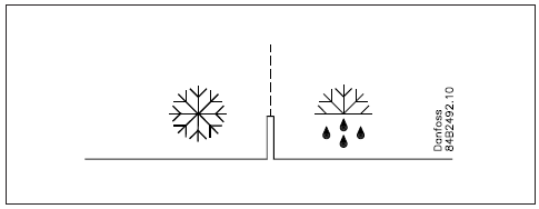
Defrost
- Depending on the application, you may choose between the following defrost methods:
- Natural: Here, the fans are kept operating during defrost
- Electric: The heating element is activated
- Hot gas: The defrost output is used to control a solenoid that lets the hot gas flow through the evaporator. The compressor is kept running to generate hot gas.
Start of defrost
- A defrost can be started in different ways:
- Interval: Defrost is started at fixed time intervals, e.g. every eighth hour
- Refrigeration time: Defrost is started at fixed refrigeration time intervals. In other words, a low need for refrigeration will ”postpone” the coming defrost.
- Schedule: Here defrost can be started at fixed times of the day and night. However, max. 6 times.
- Contact: Defrost is started with a contact signal on a digital input.
- Network: The signal for defrost is received from a system unit via the data communication.
- S5 temp In 1:1 systems the efficiency of the evaporator can be followed. Icing-up will start a defrost.
- Manual: An extra defrost can be activated from the controller’s lowest button.
- (Though not for application 4).
All the mentioned methods can be used at random – if just one of them is activated a defrost will be started.
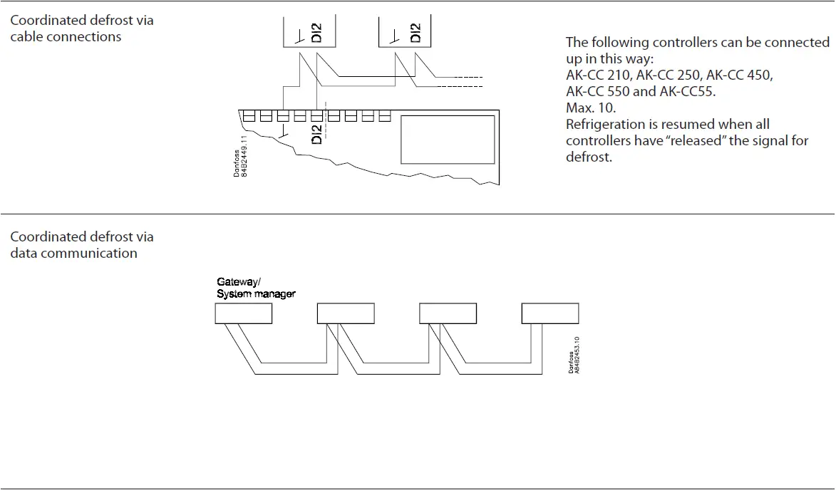
Coordinated defrost
- There are two ways in which coordinated defrost can be arranged.
- Either with wire connections between the controllers or via data communication.
Wire connections
- One of the controllers is defined to be the controlling unit and a battery module may be fitted in it so that the clock is ensured back-up. When a defrost is started, all the other controllers will follow suit and likewise start a defrost. After the defrost, the individual controllers will move into the waiting position. When all are in the waiting position, there will be a changeover to refrigeration.
- (If just one in the group demands defrost, the others will follow suit).
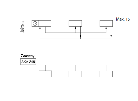
Defrost via data communication
- All controllers are fitted with a data communication module, and via the override function from a gateway, the defrost can be coordinated.
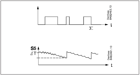
Defrost on demand
- Based on refrigeration time
When the aggregate refrigeration time has passed a set time, a defrost will be started. - Based on temperature
The controller will constantly follow the temperature at S5.
Between two defrosts, the S5 temperature will become lower the more the evaporator ices up (the compressor operates for a longer time and pulls the S5 temperature further down). When the temperature passes a set allowed variation, the defrost will be started.
This function can only work in 1:1 systems.
Service request alarm
- The controller will register the accumulated on-time in days, and a limit can be set to activate a “service request alarm” to indicate that inspection and cleaning of the fan and condenser is imminent.
- After doing so, the Runtime counter can be reset and a new period initiated.
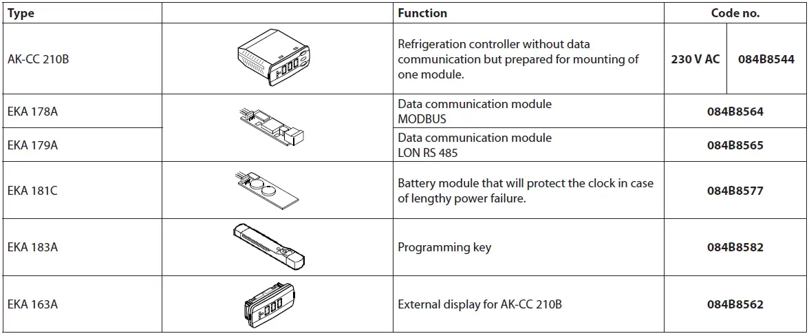
Extra module
- The controller can afterwards be fitted with an insertion module if the application requires it.
- The controller has been prepared with plug, so the module simply has to be pushed in.
- Battery module
- The module guarantees voltage to the controller if the supply voltage drops out for more than four hours. The clock function can thus be protected during a power failure.
- Data communication
- If you require operation from a PC, a data communication module has to be placed in the controller.
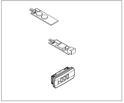
External display
- If it is necessary to indicate the temperature on the front of the refrigeration appliance, a display type EKA 163A can be mounted.
- The extra display will show the same information as the controller’s display, but does not incorporate buttons for operation. If operation from the external display is needed a display type EKA 164A must be mounted.
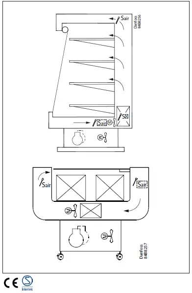
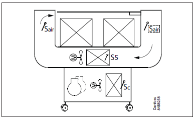
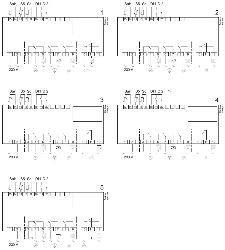
Applications
AK-CC 210B is developed for refrigerated plug-in cabinets with one or 2 compressors.
3 sensors can be connected: Sair, S5 (Defrost termination), and Sc (Condenser temperature).
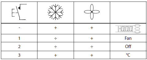
The first 3 relays are used for compressor on-off, defrost, and light, while relay 4 is configurable via “o61” application setting. The relay can be configured for 5 different applications:
- Alarm relay
- Evaporator fan control
- Rail Heat Control
- Condenser fan control
- Second compressor control
DI1, and DI2 are flexible Dry Contact inputs that can be configured for multiple functions via “o02” or “o37”
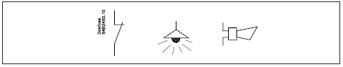
Application dependent connections
Survey of functions
| Function | Parameter | Parameter by operation via data communication |
| Normal display | ||
| Normally, the temperature value from the thermostat sensor Sair is displayed. | Display air (u56) | |
| Thermostat | Thermostat control | |
| Setpoint
Regulation is based on the set value plus a displacement, if applicable. The value is set via a push on the centre button. The set value can be locked or limited to a range with the settings in r02 and r03. The reference at any time can be seen in ”u28 Temp. ref”. |
Cutout °C | |
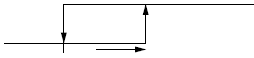
| Differential
When the temperature is higher than the reference + the set differential, the compressor relay will be cut in. It will cut out again when the temperature comes down to the set reference. |
r01 | Differential |
| Setpoint limitation Ref. Dif.
The controller’s setting range for the setpoint may be narrowed down so that much too high or much too low values are not set accidentally, with resulting damage. |
||
| To avoid a too high setting of the setpoint, the maximum. The allowable reference value must be lowered. | r02 | Max cutout °C |
| To avoid a too low setting of the setpoint, the minimum. The allowable reference value must be increased. | r03 | Min cutout °C |
| Correction of the display’s temperature showing
If the temperature of the products and the temperature received by the controller are not identical, an offset adjustment of the display temperature can be carried out. |
r04 | Disp. Adj. K |
| Temperature unit
Here you set whether the controller display is to show temperature values in °C or in °F. |
r05 | Temp. unit
°C=0. / °F=1 |
| Correction of the signal from Sair
Compensation possibility through a long sensor cable |
r09 | Adjust Sair |
| Start / stop of refrigeration
With this setting, refrigeration can be started, stopped, or a manual override of the outputs can be allowed. Start / stop of refrigeration can also be accomplished with the external switch function connected to a DI input. Stopped refrigeration will give a ”Standby alarm”. |
r12 | Main Switch
1: Start 0: Stop -1: Manual control of outputs allowed |
| Night setback value
The thermostat’s reference will be the setpoint plus this value when the controller changes over to night operation. (Select a negative value if there is to be cold ac- cumulation.) |
r13 | Night offset |
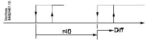
| Activation of reference displacement
When the function is changed to ON, the thermostat reference will be displaced by the value in r40. Activation can also take place via input DI1 or DI2 (defined in o02 or o37). |
r39 | Th. offset |
| Value of reference displacement
The thermostat reference and the alarm values are shifted by the following number of degrees when the displacement is activated. Activation can take place via r39 or input DI |
r40 | Th. offset K |
| Night setback (start of night signal) | ||
| Forced cool. (start of forced cooling) |
| Alarm | Alarm settings | |
| The controller can give an alarm in different situations. When there is an alarm, all the light-emitting diodes (LEDs) will flash on the controller front panel, and the alarm relay will cut in. | With data communication, the importance of the individual alarms can be defined. Setting is carried out in the “Alarm destinations” menu. | |
| Alarm delay (short alarm delay)
If one of the two limit values is exceeded, a timer function will commence. The alarm will not become active until the set time delay has been passed. The time delay is set in minutes. |
A03 | Alarm delay |
| Time delay for the door alarm
The time delay is set in minutes. The function is defined in o02 or o37. |
A04 | DoorOpen del |
| Time delay for cooling (long alarm delay)
This time delay is used during start-up, during defrost and immediately after a defrost. There will be change-over to the normal time delay (A03) when the temperature has dropped below the set upper alarm limit. The time delay is set in minutes. |
A12 | Pulldown del |
| Upper alarm limit
Here you set the alarm limit for the high temperature alarm. The limit is set in °C (absolute value). During night conditions, the limit value will be changed to the same value as the night offset. The change will only be applied for a positive night offset. The limit value will also be changed in connection with reference displacement r39. Regardless, whether this is positive or negative. |
A13 | HighLim Air |
| Lower alarm limit
Here, you set the alarm limit for low temperature alarms. The limit value is set in °C (absolute value). During night conditions, the limit will remain unchanged, while a reference displacement r39 will increase or decrease the limit with the value given by r40. |
A14 | LowLim Air |
| Delay of a DI1 alarm
A cut-out/cut-in input will result in an alarm when the time delay has passed. The function is defined in o02. |
A27 | AI.Delay DI1 |
| Delay of a DI2 alarm
A cut-out/cut-in input will result in an alarm when the time delay has passed. The function is defined in o37 |
A28 | AI.Delay DI2 |
| Condenser alarm limit
Setpoint for the condenser temperature alarm, the warning level without compressor stop. The alarm will clear when the condenser temperature is decreased to the value defined in parameter A78. |
A37 | Cond Al.Lim |
| Condenser block alarm limit
Setpoint for the condenser block alarm. Activation of this alarm can trigger an action – light off, compressor stop, or both (see parameter P92) The alarm will clear when the condenser temperature is decreased by 2 times the value defined in parameter A78. |
A54 | Cond T. Block |
| Condenser alarm delay
Delay for the condenser block alarm and potential action. The delay starts when the condenser temperature exceeds the limit in parameter A54. |
A55 | Al.Del.. Cond |
| Condenser alarm difference
Difference band below the condenser alarm temperature settings (A37 and A54) for clearing the alarms. |
A78 | Cond Al.Diff |
| Reset alarm | ||
| EKC error |
| Compressor | Compressor control | |
| The compressor relay works in conjunction with the thermostat. When the thermostat calls for refrigeration, the compressor relay will be operated. | ||
| Running times
To prevent irregular operation, values can be set for the time the compressor is to run once it has been started, and for how long it at least has to be stopped. The running times are not observed when defrosts start. |
||
| Min. ON time (in minutes) | c01 | Min. On time |
| Min. OFF time (in minutes) | c02 | Min. Off time |
| Time delay for the couplings of two compressors
Settings indicate the time that has to elapse from the first relay cuts in and until the next relay has to cut in. |
c05 | Step delay |
| The LED on the controller’s front will show whether refrigeration is in progress. | Comp Relay
Here you can read the status of the compressor relay, or you can force-control the relay in the ”Manual control” mode |
|
| Defrost | Defrost control | |
| The controller contains a timer function that is reset after each defrost start. The timer function will start a defrost if/when the interval time is passed.
The timer function starts when voltage is connected to the controller, but it is disabled the first time by the setting in d05. If there is a power failure, the timer value will be saved and will continue from here when the power returns. This timer function can be used as a simple way of starting defrosts, but it will always act as a safety defrost if one of the subsequent defrost starts is not received. The controller also contains a real-time clock. By means of settings of this clock and times for the required defrost times, defrost can be started at fixed times of the day. If there is a risk of power failure for periods longer than four hours, a battery module should be mounted in the controller. Defrost start can also be accomplished via data communication, via contact signals, or manual start-up. All starting methods will function in the controller. The different functions have to be set so that defrosts do not ”come tumbling” one after the other. Defrost can be accomplished with electricity or hot gas. The actual defrost will be stopped based on time or temperature with a signal from a temperature sensor. |
||
| Defrost method
Here you set whether defrost is to be accomplished with electricity, gas, or “non”. During defrost, the defrost relay will be cut in. |
d01 | Def. method 0 = non
1 = El 2 = Gas |
| Defrost stop temperature
The defrost is stopped at a given temperature which is measured with a sensor (the sensor is defined in d10). The temperature value is set. |
d02 | Def. Stop Temp |
| Interval between defrost starts
The function is zeroset and will start the timer function at each defrost start. When the time has expired the function will start a defrost. The function is used as a simple defrost start, or it may be used as a safeguard if the normal signal fails to appear. If master/slave defrost without clock function or without data communication is used, the interval time will be used as max. time between defrosts. If a defrost start via data communication does not take place, the interval time will be used as max. time between defrosts. When there is defrost with clock function or data communication, the interval time must be set for a somewhat longer period of time than the planned one, as the interval time will otherwise start a defrost which a little later will be followed by the planned one. In connection with a power failure, the interval time will be maintained, and when the power returns, the interval time will continue from the maintained value. The interval time is not active when set to 0. |
d03 | Def Interval (0=off) |
| Max.. defrost duration
This setting is a safety time so that the defrost will be stopped if there has not already been a stop based on temperature or via coordinated defrost. |
d04 | Max Def. time |
| Time staggering for defrost cut-ins during start-up
The function is only relevant if you have several refrigeration appliances or groups where you want the defrost to be staggered in relation to one another. The function is furthermore only relevant if you have chosen defrost with interval start (d03). The function delays the interval time d03 by the set number of minutes, but it only does it once, and this at the very first defrost taking place when voltage is connected to the controller. The function will be active after each and every power failure. |
d05 | Time Stagg. |
| Drip-off time
Here you set the time that is to elapse from a defrost and until the compressor is to start again. (The time when water drips off the evaporator). |
d06 | Drip-off time |
| Delay of fan start after defrost
Here you set the time that is to elapse from compressor start after a defrost and until the fan may start again. (The time when water is “tied” to the evaporator). |
d07 | FanStartDel |
| Fan start temperature
The fan may also be started a little earlier than mentioned under “Delay of fan start after defrost”, if the defrost sensor S5 registers a lower value than the one set here. |
d08 | FanStartTemp |
| Fan cut-in during defrost
Here you can set whether the fan is to operate during defrost. 0: Stopped (Runs during pump down) 1: Running (stopped during “fan delay”) 2: Running during pump down and defrost. After that, it is stopped. |
d09 | FanDuringDef |
| Defrost sensor
Here you define the defrost sensor. 0: None, defrost is based on time 1: S5 2: Sair |
d10 | DefStopSens. |
| Pumpdown delay
Set the time when the evaporator is emptied of refrigerant prior to the defrost. |
d16 | Pump down del. |
| Defrost on demand – aggregate refrigeration time
Here, the refrigeration time allowed without defrosting is set. If the time has passed, a defrost will be started. With setting = 0, the function is cut out. |
d18 | MaxTherRunT |
| Defrost on demand – S5 temperature
The controller will follow the effectiveness of the evaporator, and via internal calculations and measurements of the S5 temperature, it will be able to start a defrost when the variation of the S5 temperature becomes larger than required. Here you set how large a slide of the S5 temperature can be allowed. When the value is passed, a defrost will start. The function can only be used in 1:1 systems when the evaporating temperature will become lower to ensure that the air temperature will be maintained. In central systems the function must be cut out. With setting = 20, the function is cut out |
d19 | CutoutS5Dif. |
| Max. duration of -d- in the display
Controls the readout of “-d-” after defrost, so that “-d-” is shown until the temperature is ok, the set delay has expired, or a temperature alarm becomes active. |
d40 | Disp. D del. |
| If you wish to see the temperature at the defrost sensor, push the controller’s lower- most button. | Defrost temp. | |
| If you wish to start an extra defrost, push the controller’s lowermost button for four seconds.
You can stop an ongoing defrost in the same way. |
Def Start
Here you can start a manual defrost |
|
| The LED on the controller’s front will indicate whether a defrost is going on. | Defrost Relay
Here you can read the defrost relay status or you can force-control the relay in “Manual control” mode. |
|
| Hold After Def
Shows ON when the controller is operating with coordinated defrost. |
||
| Defrost State Status on defrost
1= pump down / defrost |
| Fan | Fan control | |
| The fan stopped at the cut-out compressor
Here you can select whether the fan is to be stopped when the compressor is cut out. |
F01 | Fan stop CO
(Yes = Fan stopped) |
| Delay of the fan stop when the compressor is cut out
If you have chosen to stop the fan when the compressor is cut out, you can delay the fan stop when the compressor has stopped. Here you can set the time delay. |
F02 | Fan del. CO |
| Fan stop temperature
The function stops the fans in an error situation, so that they will not provide power to the appliance. If the defrost sensor registers a higher temperature than the one set here, the fans will be stopped. There will be a restart at 2 K below the setting. The function is not active during a defrost or start-up after a defrost. With a setting +50°C, the function is interrupted. |
F04 | FanStopTemp. |
| The LED on the controller’s front will indicate whether the fan is running. | Fan Relay
Here you can read the fan relay status, or force-control the relay in “Manual control” mode. |
| Internal defrosting schedule/clock function | ||
| (Not used if an external defrosting schedule is used via data communication.) Up to six individual times can be set for the defrost start throughout the day. | ||
| Defrost start, hour setting | t01-t06 | |
| Defrost start, minute setting (1 and 11 belong together, etc.) When all t01 to t16 equal 0, the clock will not start defrosting. | t11-t16 | |
| Real-time clock
Setting the clock is only necessary when there is no data communication. In the event of a power failure of less than four hours, the clock function will be saved. When mounting a battery module the clock function can preserved longer. There is also a date indication used for registration of temperature measurements. |
||
| Clock: Hour setting | t07 | |
| Clock: Minute setting | t08 | |
| Clock: Date setting | t45 | |
| Clock: Month setting | t46 | |
| Clock: Year setting | t47 | |
| Miscellaneous | Miscellaneous | |
| Delay of the output signal after start-up
After a power failure, the controller’s functions can be delayed so that overloading of the electricity supply network is avoided. Here you can set the time delay. |
o01 | DelayOfOutp. |
| Digital input signal – DI1
The controller has a digital input 1, which can be used for one of the following functions: Off: The input is not used 1. Status display of a contact function 2. Door function: When the input is open, it signals that the door is open. The refrigeration and the fans are stopped. When the time setting in “A4” is passed, an alarm will be given and refrigeration will be resumed. 3. Door alarm: When the input is open, it signals that the door is open. When the time setting in “A4” is passed, there will be an alarm. 4. Defrost: The function is started with a pulse signal. The controller will register when the DI input is activated. The controller will then start a defrost cycle. If the signal is to be received by several controllers it is important that ALL connections are mounted the same way (DI to DI and GND to GND). 5. Main switch: Regulation is carried out when the input is short-circuited, and regulation is stopped when the input is put in pos. OFF. 6. Night operation: When the input is short-circuited, there will be a regulation for night operation. 7. Reference displacement when DI1 is short-circuited. Displacement with “r40”. 8. Separate alarm function: Alarm will be given when the input is short-circuited. 9. Separate alarm function: Alarm will be given when the input is opened. (For 8 and 9, the time delay is set in A27) 10. Case cleaning: The function is started with a pulse signal. Cf.. also a description on. |
o02 | DI 1 Config.
Definition takes place with the numerical value shown to the left.
(0 = off)
DI state (Measurement) The DI input’s present status is shown here. ON or OFF. |
| If the controller is built into a network with data communication, it must have an address, and the master gateway of the data communication must then know this address.
These settings can only be made when a data communication module has been mounted in the controller and the installation of the data communication cable has been finished. This installation is mentioned in a separate document, “RC8AC”. The address is set between 1 and 60 (119), gateway determined. The address is sent to the gateway when the menu is set in pos. ON IMPORTANT: Before you set o04, you MUST set o61. Otherwise, you will be transmitting- Ting incorrect data. |
After installation of a data communication module, the controller can be operated on an equal footing with the other controllers in ADAP- KOOL® refrigeration controls. | |
| o03 | ||
| o04 | ||
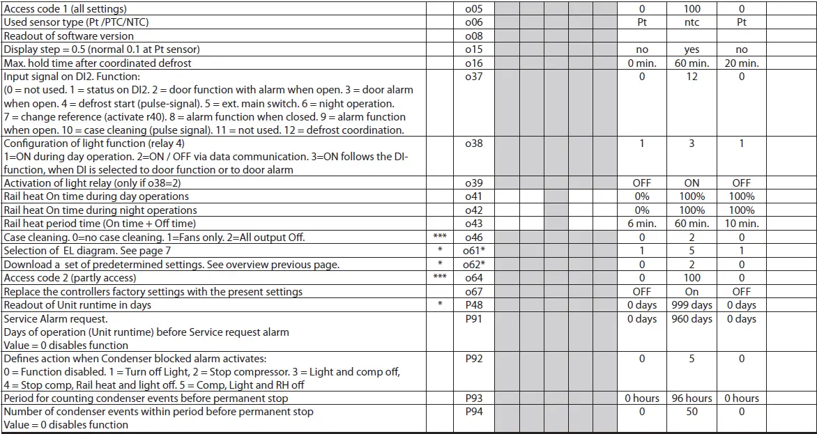
| Access code 1 (Access to all settings)
If the settings in the controller are to be protected with an access code, you can set a numerical value between 0 and 100. If not, you can cancel the function by setting 0. (99 will always give you access.) |
o05 | – |
| Sensor type
Normally, a Pt 1000 sensor with great signal accuracy is used. But you can also use a sensor with another signal accuracy. That may either be a PTC 1000 sensor (1000 ohm) or an NTC sensor (5000 Ohm at 25°C). All the mounted sensors must be of the same type. |
o06 | SensorConfig Pt = 0
PTC = 1 NTC = 2 |
| Local readout of software version | o08 | SW version |
| Display step
Yes: Gives steps of 0.5° No: Gives steps of 0.1° |
o15 | Disp. Step = 0.5 |
| Max.. standby time after coordinated defrost
When a controller has completed a defrost it will wait for a signal which tells that the refrigeration may be resumed. If this signal fails to appear for one reason or another, the controller will itself start the refrigeration when this standby time has elapsed. |
o16 | Max HoldTime |
| Digital input signal – D2
The controller has a digital input 2, which can be used for one of the following functions: Off: The input is not used. 1. Status display of a contact function 2. Door function: When the input is open it signals that the door is open. The refrig- eration and the fans are stopped. When the time setting in “A4” is passed, an alarm will be given and refrigeration resumed. 3. Door alarm: When the input is open, it signals that the door is open. When the time setting in “A4” is passed, an alarm will be given. 4. Defrost: The function is started with a pulse signal. The controller will register when the DI input is activated. The controller will then start a defrost cycle. If the signal is to be received by several controllers it is important that ALL connections are mounted the same way (DI to DI and GND to GND). 5. Main switch: Regulation is carried out when the input is short-circuited, and regulation is stopped when the input is put in pos. OFF. 6. Night operation: When the input is short-circuited, there will be a regulation for night operation. 7. Reference displacement when DI2 is short-circuited. Displacement with “r40”. 8. Separate alarm function: Alarm will be given when the input is short-circuited. 9. Separate alarm function: Alarm will be given when the input is opened. 10. Case cleaning: The function is started with a pulse signal. Cf. also description on page 4. 11. Not used 12. The input is used for coordinated defrost in conjunction with other controllers of the same type. |
o37 | DI2 config. |
| Configuration of light function (relay 4 in applications 2 and 6)
1) The relay cuts in during the day operation 2) The relay is to be controlled via data communication 3) The relay to be controlled by the door switch is defined in either o02 or o37, where the setting is selected to either 2 or 3. When the door is opened, the relay will cut in. When the door is closed again, there will be a time delay of two minutes before the light is switched off. |
o38 | Light config |
| Activation of the light relay
The light relay can be activated here, but only if defined in o38 with setting 2. |
o39 | Light remote |
| Rail heat during day operation
The ON period is set as a percentage of the time. |
o41 | Railh.ON day% |
| Rail heat during night operation
The ON period is set as a percentage of the time. |
o42 | Railh.ON ngt% |
| Rail heat cycle
The period of time for the aggregate ON time + OFF time is set in minutes. |
o43 | Railh. cycle |
| Case cleaning
The status of the function can be followed here, or the function can be started manually. 0 = Normal operation (no cleaning) 1 = Cleaning with fans operating. All other outputs are Off 2 = Cleaning with stopped fans. All outputs are off. If the function is controlled by a signal at the DI1 or DI2 input, the relevant status can be seen here in the menu. |
o46 | Case clean |
| Selection of application
The controller can be defined in various ways. Here you set which of the 5 applications is required. You can see a survey of applications. This menu can only be set when regulation is stopped, i.e., “r12” is set to 0. |
o61 | — Appl. Mode |
| Transfer a set of presettings to the controller
It is possible to select a quick setting of a number of parameters. It depends on whether an application or a room is to be controlled and whether defrost is to be stopped based on time or based on temperature. The survey can be seen on page 22. This menu can only be set when regulation is stopped, i.e., “r12” is set to 0.
After the setting, the value will return to 0. Any subsequent adjustment/setting of parameters can be made, as required. |
o62 | – |
| Access code 2 (Access to adjustments)
There is access to adjustments of values, but not to configuration settings. If the settings in the controller are to be protected with an access code, you can set a numerical value between 0 and 100. If not, you can cancel the function by setting 0. If the function is used, access code 1 (o05) must also be used. |
o64 | – |
| Save as factory settings
With this setting, you save the controller’s actual settings as a new basic setting (the earlier factory settings are overwritten). |
o67 | – |
| Runtime readout
Readout of the accumulated controller runtime in days (powered up and main switch on). Can be cleared or adjusted when the R12 main switch is off. |
P48 | Unit runtime |
| Service alarm request
Days of operation before the Service alarm request. Value = 0 disables the function |
P91 | CondServ req |
| Defines action when the Condenser blocked alarm activates
0 = Function disabled, 1 = Turn off Light, 2 = Stop compressor, 3 = Light and comp off, 4 = Stop comp, Rail heat and light off, 5 = Comp, Light and RH off |
P92 | Cond action |
| Period for counting condenser events before permanent stop
Number of hours for counting events. Events that are older than the set period are discarded. |
P93 | Cond period |
| Number of condenser events within the period before the permanent stop
The period is defined by parameter P93. Value = 0 disables the function |
P94 | Cond Ev cnt |
| – – – Night Setback 0=Day
1=Night |
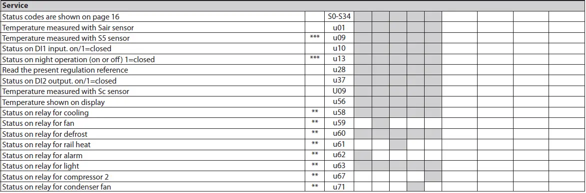
| Service | Service | |
| Temperature measured with the Sair sensor | u01 | Sair temp. |
| Temperature measured with the S5 sensor | u09 | S5 temp. |
| Status on DI1 input. on/1=closed | u10 | DI1 status |
| Status on night operation (on or off) 1=closed | u13 | Night Cond. |
| Read the present regulation reference | u28 | Temp. ref. |
| Status on DI2 output. on/1=closed | u37 | DI2 status |
| Temperature measured with Sc sensor | U09 | Sc temp. |
| The temperature is shown on the display | u56 | Display air |
| ** Status of the relay for cooling | u58 | Comp1/LLSV |
| ** Status of the relay for the fan | u59 | Fan relay |
| ** Status on relay for defrost | u60 | Def. relay |
| ** Status on relay for rail heat | u61 | Railh. relay |
| ** Status of the relay for the alarm | u62 | Alarm relay |
| ** Status of the relay for light | u63 | Light relay |
| ** Status on relay for compressor 2 | u67 | Comp2 relay |
| ** Status on relay for condenser fan | u71 | Condenser fan relay |
| *) Not all items will be shown. Only the function belonging to the selected application can be seen. |
| Fault message | Alarms | |
| In an error situation the LEDs on the front will flash and the alarm relay will be acti- vated. If you push the top button in this situation you can see the alarm report in the display. If there are more keep on pushing to see them.
There are two kinds of error reports – it can either be an alarm occurring during the daily operation, or there may be a defect in the installation. A-alarms will not become visible until the set time delay has expired. E-alarms, on the other hand, will become visible the moment the error occurs. (An A alarm will not be visible as long as there is an active E alarm.) Here are the messages that may appear: |
1 = alarm |
|
| A1: High temperature alarm | High t. alarm | |
| A2: Low temperature alarm | Low t. alarm | |
| A4: Door alarm | Door Alarm | |
| A5: Information. Parameter o16 has expired | Max Hold Time | |
| A15: Alarm. Signal from DI1 input | DI1 alarm | |
| A16: Alarm. Signal from DI2 input | DI2 alarm | |
| A45: Standby position (stopped refrigeration via R12 or DI input) (Alarm relay will not be activated) | Standby mode | |
| A59: Case cleaning. Signal from DI1 or DI2 input | Case cleaning | |
| A61: Condenser temperature alarm | Cond Alarm | |
| A80: Condenser blocked alarm | Cond blocked | |
| AA4: Service request alarm | Cond ServReq | |
| Max. def time | ||
| E1: Faults in the controller | EKC error | |
| E6: Fault in real-time clock. Check the battery / reset the clock. | – | |
| E27: Sensor error on S5 | S5 error | |
| E29: Sair sensor error | Sair error | |
| E64: Sc sensor error | Sc error | |
| Alarm destinations | ||
| The importance of the individual alarms can be defined with a setting (0, 1, 2, or 3) |
| Operating status | (Measurement) | |
| The controller goes through some regulating situations where it is just waiting for the next point of the regulation. To make these “why is nothing happening” situations
visible, you can see an operating status on the display. Push briefly (1s) the upper button. If there is a status code, it will be shown on the display. The individual status codes have the following meanings: |
EKC State:
(Shown in all menu displays) |
|
| S0: Regulating | 0 | |
| S1: Waiting for the end of the coordinated defrost | 1 | |
| S2: When the compressor is operating, it must run for at least x minutes. | 2 | |
| S3: When the compressor is stopped, it must remain stopped for at least x minutes. | 3 | |
| S4: The evaporator drips off and waits for the time to run out | 4 | |
| S10: Refrigeration was stopped by the main switch. Either with R12 or a DI input | 10 | |
| S11: Refrigeration stopped by thermostat | 11 | |
| S14: Defrost sequence. Defrosting in progress | 14 | |
| S15: Defrost sequence. Fan delay — water attaches to the evaporator | 15 | |
| S17: The Door is open. DI input is open | 17 | |
| S20: Emergency cooling *) | 20 | |
| S25: Manual control of outputs | 25 | |
| S29: Case cleaning | 29 | |
| S32: Delay on outputs during start-up | 32 | |
| S34: Condenser blocked event active | 34 | |
| Other displays: | ||
| non: The defrost temperature cannot be displayed. There is a stop based on time | ||
| -d-: Defrost in progress / First cooling after defrost | ||
| PS: Password required. Set password |
Emergency cooling will take effect when there is a lack of signal from the Sair sensor. The regulation will continue with a registered average cut-in frequency. There are two registered values – one for day operation and one for night operation.
Warning! Direct start of compressors *
- To prevent compressor breakdown, parameters c01 and c02 should be set according to the supplier’s requirements or in general:
- Hermetic Compressors c02 min. 5 minutes
- Semihermetic Compressors c02 min. 8 minutes and c01 min. 2 to 5 minutes (motor from 5 – 15 kW )
- Direct activation of solenoid valves does not require settings different from factory (0)
Operation
Display
- The values will be shown with three digits, and with a setting you can determine whether the temperature is to be shown in °C or in °F.
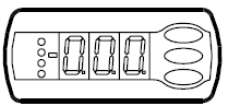
Light-emitting diodes (LED) on the front panel
The other LEDs on the front panel will light up when the belonging relay is activated.
 = Refrigeration
 = Defrost
 = Fan running
The light-emitting diodes will flash when there is an alarm.
In this situation you can download the error code to the display and cancel/sign for the alarm by giving the top knob a brief push.
Defrost
During defrost a, d- is shown in the display.
After defrost is finished, the readout of –d- will be continued until one of the following conditions are met:
- The temperature is OK (below the cut-in limit)
- A high temperature alarm becomes active
- The delay set with the d40 parameter expires
- The regulation is stopped with the “Main switch”
The buttons
When you want to change a setting, the upper and lower buttons will give you a higher or lower value, depending on the button you are pushing. But before you change the value, you must have access to the menu. You obtain this by pushing the upper button for a couple of seconds – you will then enter the column with parameter codes. Find the parameter code you want to change and push the middle buttons until the value for the parameter is shown. When you have changed the value, save the new value by once more pushing the middle button.
Examples:
Set menu
- Push the upper button until a parameter r01 is shown.
- Push the upper or the lower button and find the parameter you want to change.
- Push the middle button until the parameter value is shown.
- Push the upper or the lower button and select the new value.
- Push the middle button again to freeze the value.
Cut-out alarm, relay / receipt alarm/see alarm code
- Push the upper button shortly.
- If there are several alarm codes, they are found in a rolling stack.
- Push the uppermost or lowermost button to scan the rolling stack.
Set temperature
- Push the middle button until the temperature value is shown
- Push the upper or the lower button and select the new value
- Push the middle button again to conclude the setting.
Reading the temperature at the defrost sensor
- Push the lower button shortly
Manual start or stop of a defrost
- Push the lower button for four seconds.
- (Though not for application 4).
Get a good start
With the following procedure, you can start regulating very quickly:
- Open parameter r12 and stop the regulation (in a new and not previously set unit, r12 will already be set to 0, which means stopped regulation.)
- Select application-dependent connections based on the drawings.
- Open parameter o61 and set the electric connection number in it.
- Now select one of the preset settings from the table.
- Open parameter o62 and set the number for the array of presettings. The few selected settings will now be transferred to the menu.
- Open parameter r12 and start the regulation
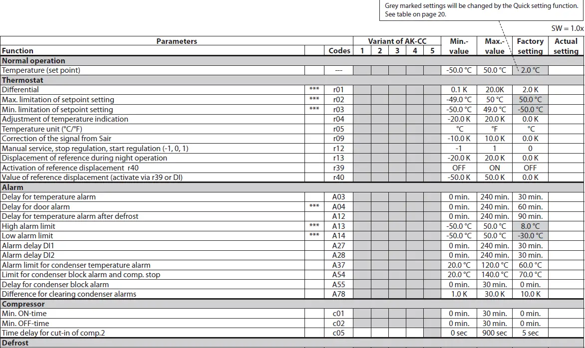
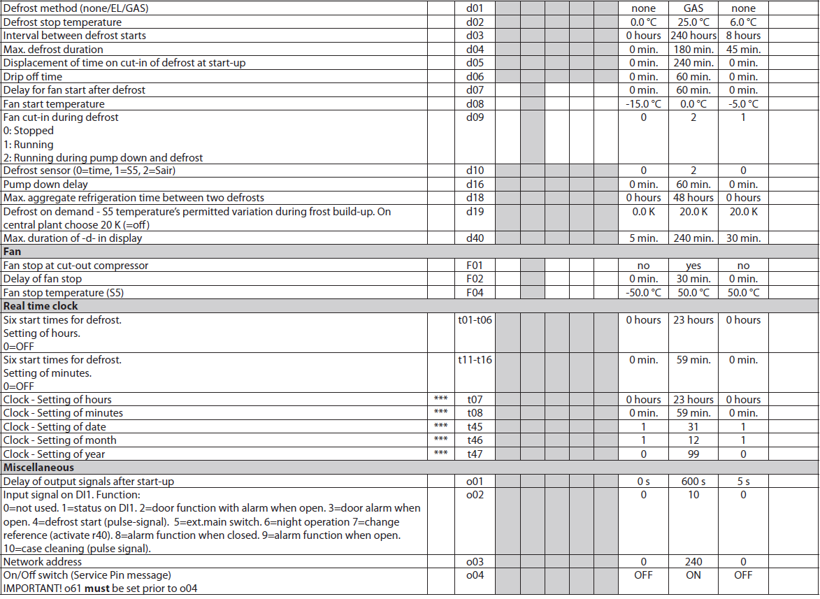
- Go through the survey of factory settings. The values in the grey cells are changed according to your choice of settings. Make any necessary changes in the respective parameters.
- For the network. Set the address in o03 and then install on the system unit by scanning, or for Lon via setting o04.
- Can only be set when regulation is stopped (r12=0)
- Can be controlled manually, but only when r12=-1
- With access code 2 the access to these menus will be limited
Factory setting
If you need to return to the factory-set values, do the following:
- Cut off the supply voltage to the controller
- Keep both buttons depressed at the same time as you reconnect the supply voltage
| Table for Quick settings | MT (cooling) cabinet | LT (frost) cabinet |
| Preset setting – via o62 | 1 | 2 |
| Temperature (SP) | 4.0 °C | -24.0 °C |
| Max. temp. setting (r02) | 6.0 °C | -22.0 °C |
| Min. temp. setting (r03) | 2.0 °C | -26.0 °C |
| Alarm limit high (A13) | 10.0 °C | -15.0 °C |
| Alarm limit low (A14) | -5.0 °C | -30.0 °C |
Override
- The controller contains a number of functions that can be used together with the override function in the master gateway / System Manager.
| Function via data com- munication | Functions to be used in the gateway’s override function | Used parameter in AK-CC 210B |
| Start of defrosting | Defrost control Time schedule | – – – Def. start |
| Coordinated defrost | Defrost control | – – – HoldAfterDef u60 Def.relay |
| Night setback | Day/night control Time schedule | – – – Night setbck |
| Light control | Day/night control Time schedule | o39 Light Remote |
Ordering
Connections
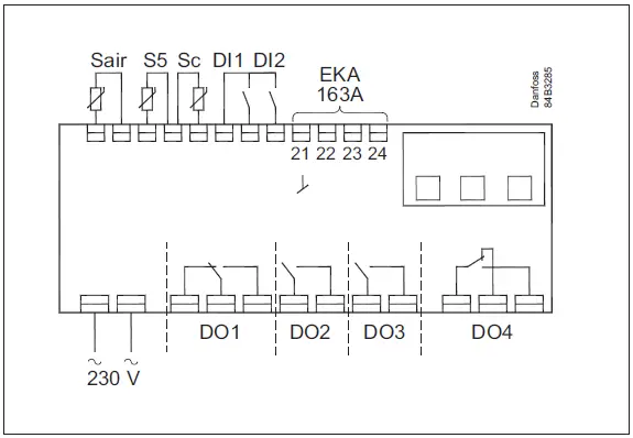
Power supply
- 230 V AC
Sensors
- Thermostat temperature is measured with Sair.
- S5 is a defrost sensor and is used if defrost has to be stopped based on temperature.
- The Sc sensor is used for monitoring and controlling the condenser temperature.
Digital On/Off signals
- A cut-in input will activate a function. The possible functions are described in menus o02 and o37.
EKA 163A – External display
- Here, an external display type EKA 163A or EKA 164A can be connected – please see the Instruction for EKA 16xA (literature no. 084R9970)
Relays
- The general uses are mentioned here. See also where the different applications are shown.
- DO1: Refrigeration. The relay will cut in when the controller demands refrigeration
- DO2: Defrost. The relay will cut in when defrost is in progress
- DO3: Light. The relay cuts in when the light has to be switched on.
- DO4: For either alarm, rail heat, fan, condenser fan or compressor 2.
- Alarm: Cf. diagram. The relay is cut in during normal operation and cuts out in alarm situations and when the controller is dead (de-energised)
- Rail heat: The relay cuts in when rail heat is to operate.
- Fans: The relay will cut in when the fans have to operate.
- Condenser fan: The relay follows the compressor except during defrost.
- Compressor 2: The relay will cut in when refrigeration step 2 has to be cut in.
Data communication
- The controller is available in several versions where data communication can be carried out with one of the following systems: MODBUS or LON-RS485.
- If data communication is used, the installation of the data communication cable must be performed correctly.
- See the separate literature No. RC8AC…
Electric noise
Cables for sensors, DI inputs and data communication must be
kept separate from other electric cables:
- Use separate cable trays
- Keep a distance between cables of at least 10 cm
- Long cables at the DI input should be avoided
Data
| Supply voltage | 230 V AC +10/-15 %. 2.5 V A, 50/60 Hz | ||
| Sensors 3 pcs off either | Pt 1000 or
PTC 1000 or NTC-M2020 (5000 ohm / 25 °C) |
||
| Accuracy | Measuring range | -60 – 99 °C | |
| Controller | ±1 K below -35 °C
±0.5 K between -35 – 25 °C ±1 K above 25 °C |
||
| Pt 1000 sensor | ±0.3 K at 0°C
±0.005 K per degree |
||
| Display | LED, 3-digits | ||
| External display | EKA 163A | ||
| Digital inputs | Signal from contact functions. Requirements for contacts: Gold plating, Cable length must be max. 15 m
Use auxiliary relays when the cable is longer. |
||
| Electrical connection cable | Max. 1.5 mm2 multi-core cable | ||
| Relays* | CE
(250 V AC) |
UL *** (240 V AC) | |
| DO1.
Refrigeration |
8 (6) A | 10 A Resistive 5FLA, 30LRA | |
| DO2. Defrost | 8 (6) A | 10 A Resistive 5FLA, 30LRA | |
| DO3. Fan | 6 (3) A | 6 A Resistive 3FLA, 18LRA
131 VA Pilot duty |
|
| DO4. Alarm | 4 (1) A
Min. 100 mA** |
4 A Resistive
131 VA Pilot duty |
|
| Environments | 0 – 55 °C, during operations
-40 – 70 °C, during transport |
||
| 20 – 80% Rh, not condensed | |||
| No shock influence/vibrations | |||
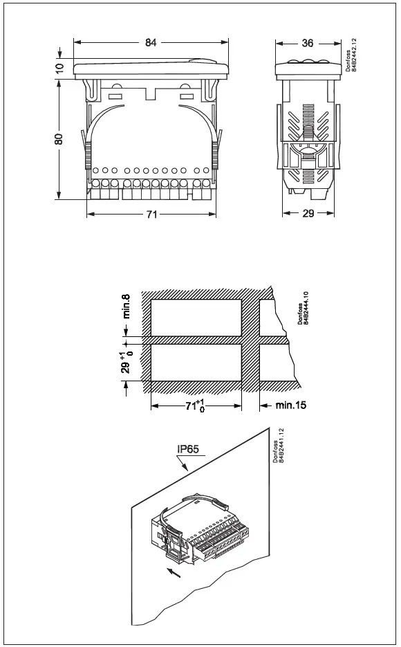
| Density | IP 65 from the front.
Buttons and packing are embedded in the front. |
||
| Escapement reserve for the clock |
4 hours |
||
| Approvals
|
EU Low Voltage Directive and EMC demands must be complied with
LVD tested acc. EN 60730-1 and EN 60730-2-9, A1, A2 EMC tested acc. EN 61000-6-3 and EN 61000-6-2 |
||
- DO1 and DO2 are 16 A relays. The mentioned 8 A can be increased up to 10 A when the ambient temperature is kept below 50 °C. DO3 and DO4 are 8A relays. Max. The load must be kept.
- Gold plating ensures a good function with small contact loads
- UL approval based on 30000 couplings.
Danfoss can accept no responsibility for possible errors in catalogues, brochures, and other printed material. Danfoss reserves the right to alter its products without notice. This also applies to products already on order, provided that such alterations can be made without subsequent changes being necessary in specifications already agreed upon.d All trademarks in this material are the property of the respective companies. Danfoss and the Danfoss logotype are trademarks of Danfoss A/S. All rights reserved
FAQ
- How do I set the defrost sensor?
- To set up the defrost sensor, mount it directly on the evaporator for optimal signal reception. This ensures efficient defrost cycles.
- How can I configure condenser temperature alarms?
- You can configure condenser temperature alarms by setting the Condenser Alarm limit and Condenser Block Alarm limit. Define actions based on these limits in parameter P92.
- What should I do if the compressors are stopped due to critical alarms?
- If compressors are stopped due to critical alarms, a manual reset is required before they can start again. Check parameters P93, P94, and P92 for configuring compressor behavior.
Documents / Resources
 |
Danfoss AK-CC 210B Controller For Temperature Control [pdf] User Guide AK-CC 210B Controller For Temperature Control, AK-CC 210B, Controller For Temperature Control, Temperature Control, Control |