CTC CONNECT ACCESS360 Connect Bridge Gateway

Introduction
The ACCESS360 functions as a network controller and Bluetooth® gateway that facilitates bi-directional data transfer with CTC Connect Wireless Sensors within range.ACCESS360 can accept an unlimited number of sensor inputs with 20 concurrent Bluetooth® connections at one time.Rated IP67, the ACCESS360 can withstand harsh environments including temperatures ranging from -4 °F to 158 °F (-20 °C to 70 °C). A cover featuring four self-tapping screws allows the box to be sealed from the elements. There is no need to remove the cover, except if the SD card needs to be replaced. When the gateway is fully powered on, a green LED light will be visible through the clear lid.
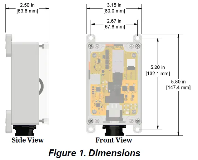
Product Dimensions
Mounting Instructions
- Molded mounting brackets are included on the enclosure. Wall anchoring screws are not included.
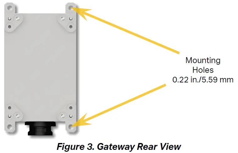
- Mount the gateway to a solid surface using mounting bolts as shown in Figure 4 below.

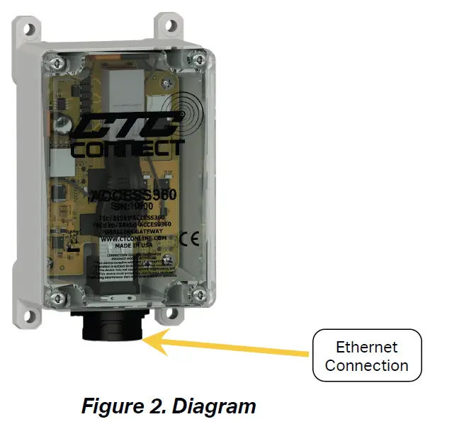
Ethernet Connection
Assemble the protective dust shield on the ethernet cable before installation. Connect the cable to the socket at the base of the gateway. Slide the dust shield up onto the connection port and twist it into place. To prevent build-up of condensation, ensure the ethernet cable entry point is facing downward.
Note: The ACCESS360 requires power over ethernet to function. If your network is not capable of supplying power over ethernet, an external PoE injector supporting IEEE 802.3af or above is required.
Device Setup
Connecting to a Network
- Establish a physical connection between the gateway and the local network using the ethernet port and a Category 5 or higher ethernet cable. The gateway will power on automatically and two indicator LEDs will begin to blink, one orange and one green.
- Wait until the orange LED remains solidly lit.
- On a computer connected to the network, open a browser and navigate to http://ctcap-XXXX, where XXXX is the eight-digit serial number of your gateway. The following screen will be displayed.

- If the gateway is intended to be used as a primary connection point, click Primary. This will lead to the user login screen.
- If the gateway is intended to be an intermediary connection point between a group of sensors and a primary gateway, click the Secondary button. This will lead to an additional setup screen.
- Enter the serial number of the primary gateway into the text field. Use the Test Connection button to verify that the two gateways are able to communicate.

- Press the Submit button to complete.

Creating a New Account
- From the login screen, click the Create button at the bottom of the window.

- Enter the required user information: first and last name, email address, and password.
- Click the Details button to view any additional information, if desired.
- Click the Register button. The app will return to the login screen.
- Log in to the newly created account.
- If prompted, check the associated email address for a verification email.
Note: The first account created on the network will automatically be assigned the Admin role. All subsequent users must have their roles elevated, as described in the following section.
Modifying User Accounts
- While logged into an account with Admin privileges, click the Accounts button on the left side of the dashboard.

- Select the user account you wish to edit.
- Click the pencil icon.

- Modify account information as desired.
- Click the Save button to complete
Resetting User Password
- Ensure that the gateway is connected to a network with internet access.
- From the login screen, select the Forgot Password? option.

- Enter the user’s email address.

- Create a new password, and enter the verification code sent via email. Click Submit

- The user will be returned to the login screen, where they will be able to log in with the new credentials.
Performing a Software Update
- Ensure that the gateway is connected to a network with internet access.
- While logged into an account with Admin privileges, click the Settings button on the left side of the dashboard

- Select the Software Update option.

- If an update is available, it will be shown on this page. Click the Get Update button to update the software

Executing Functionality
Note: Proceeding with any of the following requires the user to have either Analyst or Admin privileges.
Connecting a Sensor
- Unscrew the sensor cap and plug in the battery.
- From the dashboard, click the Devices dropdown on the left then click on Wireless Sensors.

- The sensor will automatically connect and will show in the list of available sensors.
Note: Sensor connection status will also appear in notifications
Programming a Dynamic Sensor
- From the dashboard, click the Devices dropdown on the left then click on Wireless Sensors

- Select the desired sensor from the list.
- Modify any sensor setting by using the 3-dot button located in its field

Note: WS100 Series sensors are not field reprogrammable.
Taking a Reading
- From the dashboard, click the Devices dropdown on the left then click on Wireless Sensors

- Find the desired dynamic sensor among the list of connected devices and click on it.
- On the sensor page, click the Take Reading button.

Once the reading is complete, the page will automatically refresh with the resulting data capture.
Viewing Process Control Sensors
- From the dashboard, click the Devices dropdown on the left then click on Wireless Sensors

- Find the desired sensor among the list of connected devices and click on it.
Process Control Sensors
- The resulting screen will display all available information about the sensor

Create a Machine Group
- From the dashboard, click the Machine Groups button on the left

- Click the New Machine button

- Enter machine information: name, description, and location.

- Click the Save button to complete

Add Sensor to a Machine Group
- From the dashboard, click the Machine Groups button on the left.

- Select the desired machine from the available list.
- Press the Add Sensor button.

- From the drop-down menu, select any desired sensor from the list of available options

- Press the Submit button to complete.

FCC Statement
FCC Compliance Statement
This device complies with part 15 of the FCC Rules. Operation is subject to the following two conditions:
- this device may not cause harmful interference, and
- this device must accept any interference received, including interference that may cause undesired operation.
CAUTION: The grantee is not responsible for any changes or modifications not expressly approved by the party responsible for compliance. Such modifications could void the user’s authority to operate the equipment. NOTE: This equipment has been tested and found to comply with the limits for a Class B digital device, pursuant to part 15 of the FCC Rules. These limits are designed to provide reasonable protection against harmful interference in a residential installation. This equipment generates, uses, and can radiate radio frequency energy, and if not installed and used in accordance with the instructions, may cause harmful interference to radio communications. However, there is no guarantee that interference will not occur in a particular installation. If this equipment does cause harmful interference to radio or television reception, which can be determined by turning the equipment off and on, the user is encouraged to try to correct the interference by one or more of the following measures:
- Reorient or relocate the receiving antenna.
- Increase the separation between the equipment and the receiver.
- Connect the equipment to an outlet on a circuit different from that to which the receiver is connected.
- Consult the dealer or an experienced radio/TV technician for help.
RF exposure statement
This equipment complies with the FCC RF radiation exposure limits set forth for an uncontrolled environment. This equipment should be installed and operated with a minimum distance of 20cm between the radiator and any part of your body
Maintenance
Once the system has been installed, it requires minimal maintenance. Basic checks to ensure system integrity should be made periodically. Visual inspection should include examinations for the following:
- No visible electrical burns or smoke inside the enclosure.
- No moisture or condensation is present inside the enclosure.
Warranty and Refund
Please visit www.ctconline.com to view a complete recapitulation of our warranty and refund policies.
Disclaimer
The ACCESS360 contains software and firmware proprietary to CTC. Use of the ACCESS360 is, at all times, subject to the CTC’s then-current Software End User License Agreement available at www.ctconline.com. All data and information provided by, or collected from, you is subject to CTC’s Privacy Policy available at www.ctconline.com.
Documents / Resources
 |
CTC CONNECT ACCESS360 Connect Bridge Gateway [pdf] Installation Guide ACCESS360, ACCESS360 Connect Bridge Gateway, Connect Bridge Gateway, Bridge Gateway, Gateway |


